EP0659164B1 - Hebebühne - Google Patents
Hebebühne Download PDFInfo
- Publication number
- EP0659164B1 EP0659164B1 EP93918766A EP93918766A EP0659164B1 EP 0659164 B1 EP0659164 B1 EP 0659164B1 EP 93918766 A EP93918766 A EP 93918766A EP 93918766 A EP93918766 A EP 93918766A EP 0659164 B1 EP0659164 B1 EP 0659164B1
- Authority
- EP
- European Patent Office
- Prior art keywords
- platform
- mast
- masts
- slide
- interchangeable
- Prior art date
- Legal status (The legal status is an assumption and is not a legal conclusion. Google has not performed a legal analysis and makes no representation as to the accuracy of the status listed.)
- Expired - Lifetime
Links
- 230000008878 coupling Effects 0.000 claims abstract description 10
- 238000010168 coupling process Methods 0.000 claims abstract description 10
- 238000005859 coupling reaction Methods 0.000 claims abstract description 10
- 230000008859 change Effects 0.000 description 2
- 230000006978 adaptation Effects 0.000 description 1
- 238000006243 chemical reaction Methods 0.000 description 1
- 238000010276 construction Methods 0.000 description 1
- 230000007812 deficiency Effects 0.000 description 1
- 230000006735 deficit Effects 0.000 description 1
- 238000010586 diagram Methods 0.000 description 1
- 230000036541 health Effects 0.000 description 1
- 230000003993 interaction Effects 0.000 description 1
- 238000009420 retrofitting Methods 0.000 description 1
- 230000007704 transition Effects 0.000 description 1
- 238000010626 work up procedure Methods 0.000 description 1
Images


Classifications
-
- B—PERFORMING OPERATIONS; TRANSPORTING
- B66—HOISTING; LIFTING; HAULING
- B66F—HOISTING, LIFTING, HAULING OR PUSHING, NOT OTHERWISE PROVIDED FOR, e.g. DEVICES WHICH APPLY A LIFTING OR PUSHING FORCE DIRECTLY TO THE SURFACE OF A LOAD
- B66F11/00—Lifting devices specially adapted for particular uses not otherwise provided for
- B66F11/04—Lifting devices specially adapted for particular uses not otherwise provided for for movable platforms or cabins, e.g. on vehicles, permitting workmen to place themselves in any desired position for carrying out required operations
-
- E—FIXED CONSTRUCTIONS
- E04—BUILDING
- E04G—SCAFFOLDING; FORMS; SHUTTERING; BUILDING IMPLEMENTS OR AIDS, OR THEIR USE; HANDLING BUILDING MATERIALS ON THE SITE; REPAIRING, BREAKING-UP OR OTHER WORK ON EXISTING BUILDINGS
- E04G1/00—Scaffolds primarily resting on the ground
- E04G1/18—Scaffolds primarily resting on the ground adjustable in height
- E04G1/20—Scaffolds comprising upright members and provision for supporting cross-members or platforms at different positions therealong
Definitions
- the invention relates to a lifting platform with a platform which is supported in a height-adjustable manner on at least one supporting mast and which is connected to the mast (s) which can be assembled from stackable mast elements by means of a slide which can be driven.
- these lifts are primarily of single-mast design, but two-mast designs have also become known.
- the lifting masts of these lifts can each be set up from a base element supported on a base frame by stacking individual mast elements on top of one another with the aid of the platform that is raised up to the desired height or the predetermined height specified by the building to be processed.
- the platform can also be assembled by stringing together individual platform elements up to a certain maximum size, but depending on the one or two mast design, is permanently connected to or to the mast (s) with one or two sledges, so that the platform or the sled sits on the foot element of the masts, resulting in a transportable basic lifting device that can even be moved when the frame is designed as a chassis, which, when in use, is expanded and enlarged in a modular manner due to the mast and platform elements available and to the respective structural conditions and Working conditions can be adjusted.
- Rack-and-pinion drive devices provide safe, interference-free travel of the platform along the support masts, with appropriate guides and safety devices ensuring safe operation, and these lifts have already proven themselves in a wide variety of facade work up to the greatest heights.
- the lifts allow working with an optimal access height, they offer large platform areas and thus space for material, aggregates, machines, etc., they form a uniform elevator for people and materials, they enable better working conditions in terms of health and social considerations , they leave a building essentially unaffected despite the facade work to be carried out and, last but not least, unauthorized use of these lifts is largely ruled out.
- the lifts have so far been limited in terms of their lateral reach and to capture the maximum platform length of building and facade areas, the lifts would have to be dismantled and laterally rebuilt or lined up side by side, which is not only cumbersome, but also complex and often uneconomical , because if multiple stages were used, not all stages would be fully utilized at the same time.
- the invention is therefore based on the object to eliminate these deficiencies and to create a lifting platform of the type described, which is distinguished without any impairment of its stage-specific advantages by the rational increase in its range and its variability with regard to the possible uses.
- the invention solves this problem in that more masts are provided as sledges and sledges and / or masts have a coupling device for the optional connection of the platform to various supporting masts.
- the measure according to the invention to make the platform decouplable from its originally assigned mast, at the same time opens up the rational possibility of being able to assign any number of masts to a platform, and then allows a single platform to be combined with different masts as required and this platform optionally there use wherever it is needed.
- the individual masts are assembled in the usual way with the help of the platform, with each mast being based on its own base frame, and the platform, together with each of these masts, can fully meet all the requirements of a lifting platform.
- the drive and control devices of the lifting platform are accommodated in the slide of the platform, these devices can also be used together with each of the various masts and despite the practically arbitrary range extension, the additional effort required remains relatively low.
- the coupling devices required for removing or attaching the platform from or to the masts can be designed in a wide variety of ways; they merely have to ensure that the slide and mast interact properly after attachment and that the interacting guide and drive parts are easily separated when removed.
- the carriage could be equipped, for example, with support parts which can be moved from an operating position into an open position and which, in the operating position, reach around or behind the carriage guides of the supporting masts and release them in the open position.
- support parts could be swiveling roller systems or other slide parts interacting in a form-fitting manner with mast guides, which would in principle enable the known supporting poles to be used further and would only require a suitable retrofitting or conversion of the conventional sledges.
- the supporting masts are constructed on a base element which, as a coupling device, forms a receptacle for an interchangeable element which is adapted to the mast elements with respect to the slide guide and drive parts and which is connected to the lowest of the mast elements attached to the base element.
- the interaction of the interchangeable element and the base element makes it possible to use conventional slides and conventional mast elements built on the base element, since the sled for moving from mast to mast is simply moved onto the interchangeable element and is moved together with this interchangeable element, which is common to every mast with the base element to a certain extent replaced the foot element of the conventional masts. From the interchangeable element, the carriage or the platform can then be raised without difficulty onto the subsequent mast element and from there further along the mast.
- the known lifting platform system can be converted according to the invention with little additional effort, since only one of the usual mast elements has to be built onto the upright part of the base element and a serving as an interchangeable element Mast element on one of its long sides is to be opened for placement on the upright part, in order then to be able to be fastened in the usual way to the underside of the lowest mast element.
- the platform can be equipped with a chassis for moving, the platform being supported on the chassis via a lifting device, so that, without additional aids, such as, for example, truck cranes, the platform can be removed from one of the masts, brought to the desired location and reconnected to the corresponding mast, which is why the sled with the lifting device can be easily brought to the correct coupling height for coupling and uncoupling.
- the undercarriage can be rail-free but also rail-bound and it can be moved manually or by motor or the like, so that an optimal adaptation of the platform change to the respective circumstances is possible.
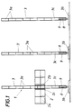
- the lifting platform 1 shown comprises a platform 2 and at least one supporting mast 3, the platform 2 being vertically movable on the masts 3.
- the platform 2 can be assembled in a modular manner from platform elements 2a, which can be strung together on both sides of a basic element 2b up to a certain maximum length, the basic element 2b being connected to the supporting mast 3 via a drivable slide 2c and being guided along this.
- the support masts 3 can also be built up from individual stackable mast elements 3a to the required height, each of the elements 3a having corresponding slide guides 4 and being provided with adjoining rack sections 5 for the slide drive.
- the platform 2 connected to a supporting mast 3 can therefore move up and down along the slide guides 4 via its slide 2c, the drive device 6 of the slide 2c having a pinion (not shown further) which engages in the toothed racks 5.
- the carriage 2c can be uncoupled and coupled from the mast 3 or to the mast 3.
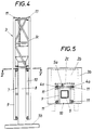
- the support masts 3 are built on a base element 3b, which as a coupling device 7 has an upright part 8, which forms a receptacle for an interchangeable element 9.
- the interchangeable element 9 is aligned with the other mast elements 3 and, in order to take over the slide 2c, also has drive and guide parts 5a, 4a aligned with the toothed racks 5 of the mast elements 3a and their slide guides 4.
- the interchangeable element 9 can now be placed with a lifting device (not shown), for example a truck crane, together with the connected slide 2c with the open longitudinal side 10 on the correspondingly narrow upright part 8 and with conventional connecting parts 11 on the underside of the upright part 8 attached mast element 3c, as shown in FIGS. 4 and 5 for an interchangeable element with a carriage 2c indicated only by dashed lines.
- a lifting device for example a truck crane
- the platform 2 is to be used on another supporting mast 3, this platform only needs to move the supporting mast down to the interchangeable element 9, then the platform is held by a lifting device, the interchangeable element 9 is removed from the mast element 3c and the platform with interchangeable element 9 is removed from the base element 3b and to be brought to the next mast 3.
- the connection is made like any other Support mast by placing the interchangeable element 9 on the upright part 8 and connecting to the mast element 3c constructed on the upright part and the desired lateral offset of the platform 2 is finished.
Landscapes
- Engineering & Computer Science (AREA)
- Structural Engineering (AREA)
- Architecture (AREA)
- Mechanical Engineering (AREA)
- Civil Engineering (AREA)
- Life Sciences & Earth Sciences (AREA)
- Geology (AREA)
- Forklifts And Lifting Vehicles (AREA)
- Types And Forms Of Lifts (AREA)
Abstract
Description
- Die Erfindung bezieht sich auf eine Hebebühne mit einer an wenigstens einem Tragmast der Höhe nach verfahrbar abgestützten Plattform, die an dem bzw. den aus aufeinandersetzbaren Mastelementen zusammenbaubaren Mast(en) jeweils über einen antreibbar geführten Schlitten angeschlossen ist.
- Wie beispielsweise aus der EP-A-0 106 506 hervorgeht, gibt es diese Hebebühnen vor allem in Einmastausführung, doch sind auch schon Zweimastausführungen bekannt geworden. Die Tragmaste dieser Hebebühnen können jeweils von einem auf einem Grundgestell abgestützten Fußelement aus durch Übereinandersetzen einzelner Mastelemente mit Hilfe der eigenen hochfahrenden Plattform bis zur gewünschten, vom zu bearbeitenden Gebäude od. dgl. vorgegebenen Höhe aufgebaut werden. Die Plattform läßt sich ebenfalls durch Aneinanderreihen einzelner Plattformelemente bis zu einer bestimmten Maximalgröße zusammensetzen, ist aber je nach Ein- oder Zweimastausführung mit einem oder zwei Schlitten bleibend am bzw. an den Mast(en) angeschlossen, so daß bei abgebauter Hebebühne die Plattform bzw. die Schlitten am Fußelement der Maste sitzen und sich so ein transportables, bei Ausbildung des Gestells als Fahrgestell sogar verfahrbares Hebebühnen-Grundgerät ergibt, das bedarfsweise im Einsatz auf Grund der zur Verfügung stehenden Mast- und Plattformelemente modulartig erweitert und vergrößert und an die jeweiligen baulichen Gegebenheiten und Arbeitsbedingungen angepaßt werden kann. Zahnstangen- Ritzelantriebseinrichtungen bringen eine sichere, störunanfällige Verfahrbarkeit der Plattform den Tragmasten entlang mit sich, wobei entsprechende Führungen und Sicherungseinrichtungen einen gefahrlosen Betrieb gewährleisten, und diese Hebebühnen haben sich auch bereits bei den verschiedensten Fassadenarbeiten bis zu größten Höhen durchaus bewährt. Im Vergleich zu festen Baugerüsten erlauben die Hebebühnen ein Arbeiten mit optimaler Zugriffshöhe, sie bieten große Plattformflächen und damit Platz für Material, Aggregate, Maschinen u.dg., sie bilden einen einheitlichen Personen- und Materialaufzug, sie ermöglichen in gesundheitlicher und sozialer Hinsicht bessere Arbeitsbedingungen, sie lassen ein Gebäude trotz durchzuführender Fassadenarbeiten im wesentlichen unbeeinträchtigt und nicht zuletzt ist ein unbefugtes Benutzen dieser Hebebühnen weitgehend ausgeschlossen. Allerdings sind die Hebebühnen bisher in ihrer seitlichen Reichweite beschränkt und zum Erfassen die maximale Plattformlänge übersteigender Gebäude- und Fassadenbereiche müßten die Hebebühnen abgebaut und jeweils seitlich versetzt wieder aufgebaut oder Bühne an Bühne nebeneinandergereiht werden, was nicht nur umständlich, sondern auch aufwendig und vielfach unwirtschaftlich ist, da beim Einsatz mehrerer Bühnen nicht alle Bühnen gleichzeitig voll ausgelastet wären.
- Der Erfindung liegt daher die Aufgabe zugrunde, diese Mängel zu beseitigen und eine Hebebühne der eingangs geschilderten Art zu schaffen, die sich ohne jede Beeinträchtigung ihrer bühnenspezifischen Vorteile durch die rationelle Vergrößerung ihrer Reichweite und ihre Variabilität hinsichtlich der Einsatzmöglichkeiten auszeichnet.
- Die Erfindung löst diese Aufgabe dadurch, daß mehr Tragmaste als Schlitten vorgesehen sind und Schlitten und/oder Maste eine Koppelungseinrichtung zum wahlweisen Anschluß der Plattform an verschiedenen Tragmasten aufweisen. Die erfindungsgemäße Maßnahme, die Plattform von ihrem ihr ursprünglich zugeordneten Tragmast abkoppelbar zu machen, eröffnet gleichzeitig die rationelle Möglichkeit, einer Plattform beliebig viele Tragmaste zuordnen zu können, und erlaubt es dann, eine einzige Plattform bedarfsweise mit verschiedenen Tragmasten zu kombinieren und diese Plattform wahlweise dort einzusetzen, wo sie gerade gebraucht wird. Die einzelnen Tragmaste werden in üblicher Weise mit Hilfe der Plattform montiert, wobei jeder Mast auf einem eigenen Bodengestell gründet, und die Plattform kann zusammen mit jedem dieser Maste alle Ansprüche einer Hebebühne voll befriedigen. Da die Antriebs- und Steuerungseinrichtungen der Hebebühne im Schlitten der Plattform untergebracht sind, können diese Einrichtungen auch zusammen mit jedem der verschiedenen Maste genützt werden und trotz der praktisch beliebigen Reichweitenausdehnung bleibt der erforderliche Mehraufwand verhältnismäßig gering. Die zum Abnehmen bzw. Ansetzen der Plattform von bzw. an den Masten erforderlichen Koppelungseinrichtungen können unterschiedlichst ausgebildet sein, sie müssen lediglich für ein einwandfreies Zusammenwirken von Schlitten und Mast nach dem Ansetzen und eine einfache Trennung der zusammenwirkenden Führungs- und Antriebsteile beim Abnehmen sorgen.
- Als Koppelungseinrichtung könnte der Schlitten beispielsweise mit von einer Betriebsstellung in eine Offenstellung bewegbaren Stützteilen ausgestattet sein, die in der Betriebsstellung die Schlittenführungen der Tragmaste umoder hintergreifen und diese in Offenstellung freigeben. Ein solcher Schlitten braucht lediglich mit Hilfe eines geeigneten Zusatzgerätes an die Tragmaste herangebracht zu werden und läßt sich dann einfach durch Verstellen der Stützteile in die Betriebsstellung ankoppeln. Diese Stützteile könnten schwenkbare Rollensysteme oder andere mit Mast-Führungen formschlüssig zusammenwirkende Schlittenteile sein, was grundsätzlich die Weiterverwendung der bekannten Tragmaste ermöglichen und nur eine geeignete Umrüstung oder einen Umbau der üblichen Schlitten erfordern würde.
- Eine besonders vorteilhafte Konstruktion entsteht allerdings dadurch, daß die Tragmaste auf einem Basiselement aufgebaut sind, das als Koppelungseinrichtung eine Aufnahme für ein hinsichtlich der Schlittenführungs- und -antriebsteile an die Mastelemente angepaßtes, an das unterste der am Basiselement befestigten Mastelemente anschließendes Wechselelement bildet. Durch das Zusammenwirken von Wechselelement und Basiselement ist es möglich, herkömmliche Schlitten und auf das Basiselement aufgebaute herkömmliche Mastelemente zu verwenden, da der Schlitten zum Versetzen von Mast zu Mast einfach auf das Wechselelement aufgefahren und zusammen mit diesem Wechselelement versetzt wird, das bei jedem Tragmast zusammen mit dem Basiselement gewissermaßen das Fußelement der herkömmlichen Tragmaste ersetzt. Vom Wechselelement läßt sich der Schlitten bzw. die Plattform dann ohne Schwierigkeiten auf das anschließende Mastelement und von hier weiter den Mast entlang hochfahren.
- Ist das Wechselelement mit einer offenen Längsseite auf einen die Aufnahme bildenden Steherteil des Basiselementes aufsetzbar und am untersten Mastelement anhängbar, kann mit wenig Mehraufwand das bekannte Hebebühnensystem erfindungsgemäß umgerüstet werden, da dazu lediglich eines der üblichen Mastelemente auf den Steherteil des Basiselementes aufgebaut werden muß und ein als Wechselelement dienendes Mastelement an einer seiner Längsseiten zum Aufsetzen auf den Steherteil zu öffnen ist, um dann in üblicher Weise an der Unterseite des untersten Mastelementes befestigt werden zu können.
- Eine weitere Möglichkeit des Ansetzens eines Wechselelementes ergibt sich dadurch, daß das Wechselelement in Halterungen des Basiselementes unter Ausrichtung der Schlittenführungs- und -antriebsteile auf das unterste Mastelement einsteckbar ist, wodurch eine unmittelbare Befestigung des Wechselelementes am untersten Mastelement entfallen könnte. Hier muß allerdings für eine Halterung des Wechselelementes am Basiselement gesorgt sein, bei der die Führungs- und Antriebsteile von Wechselelement und Mastelementen einwandfrei miteinander fluchten und der Übergang vom Wechselelement auf den Tragmast für den Schlitten funktionssicher ermöglicht ist.
- Um das Versetzen der Plattform von einem Mast zum anderen zu erleichtern, kann die Plattform mit einem Fahrgestell zum Verfahren ausgerüstet sein, wobei die Plattform über eine Hebevorrichtung am Fahrgestell abgestützt ist, so daß ohne zusätzliche Hilfsmittel, wie es beispielsweise LKW-Kräne sein können, die Plattform von dem einen Tragmast abgenommen, zum gewünschten Einsatzort gebracht und dort am entsprechenden Tragmast wieder angeschlossen werden kann, wozu der Schlitten mit der Hebevorrichtung schwierigkeitslos zum An- und Abkoppeln in die jeweils richtige Koppelungshöhe zu bringen ist. Das Fahrgestell kann dabei schienenfrei aber auch schienengebunden sein und es kann händisch oder motorisch bewegt werden od. dgl., so daß eine optimale Anpassung des Plattformwechsels an die jeweiligen Gegebenheiten möglich ist.
- In der Zeichnung ist der Erfindungsgegenstand an Hand eines Ausführungsbeispieles rein schematisch veranschaulicht, und zwar zeigen
- Fig. 1
- eine erfindungsgemäße Hebebühne in Vorderansicht,
- Fig. 2 und 3
- jeweils einen Teil einer zugehörigen Plattform bzw. eines Tragmastes im Schaubild größeren Maßstabes,
- Fig. 4
- einen Teil eines Tragmastes mit einem angesetzten Wechselelement in Rückansicht und
- Fig. 5
- einen Querschnitt nach der Linie V-V der Fig. 4
- Die dargestellte Hebebühne 1 umfaßt eine Plattform 2 und wenigstens einen Tragmast 3, wobei die Plattform 2 der Höhe nach verfahrbar an den Masten 3 abstützbar ist. Die Plattform 2 läßt sich modulartig aus Plattformelementen 2a zusammensetzen, die beidseits an ein Grundelement 2b bis zu einer bestimmten Maximallänge aneinandergereiht werden können, wobei das Grundelement 2b über einen antreibbaren Schlitten 2c am Tragmast 3 angeschlossen und diesem entlang geführt werden kann. Auch die Tragmaste 3 sind aus einzelnen übereinandersetzbaren Mastelementen 3a bis zur erforderlichen Höhe aufbaubar, wobei jedes der Elemente 3a entsprechende Schlittenführungen 4 aufweist und mit aneinanderschließenden Zahnstangenabschnitten 5 für den Schlittenantrieb versehen sind. Die an einen Tragmast 3 angeschlossene Plattform 2 kann daher über ihren Schlitten 2c den Schlittenführungen 4 entlang auf- und abfahren, wobei die Antriebseinrichtung 6 des Schlittens 2c ein nicht weiter dargestelltes, in die Zahnstangen 5 eingreifendes Ritzel aufweist.
- Um die Plattform 2 wahlweise mit dem einen oder anderen Tragmast 3 verwenden zu können, ist der Schlitten 2c vom Mast 3 bzw. an den Mast 3 ab- und ankoppelbar. Dazu sind die Tragmaste 3 auf einem Basiselement 3b aufgebaut, das als Koppelungeinrichtung 7 einen Steherteil 8 aufweist, der eine Aufnahme für ein Wechselelement 9 bildet. Das Wechselelement 9 ist bis auf eine offene Längsseite 10 den anderen Mastelementen 3 angeglichen und weist zur Übernahme des Schlittens 2c auch zu den Zahnstangen 5 der Mastelemente 3a und deren Schlittenführungen 4 fluchtende Antriebs- und Führungsteile 5a, 4a auf. Das Wechselelement 9 läßt sich nun mit einem nicht weiter dargestellten Hebezeug, beispielsweise einem LKW-Kran, zusammen mit dem angeschlossenen Schlitten 2c mit der offenen Längsseite 10 auf den entsprechend schmal gebauten Steherteil 8 aufsetzen und mit üblichen Anschlußteilen 11 an der Unterseite des am Steherteil 8 befestigten Mastelementes 3c anhängen, wie dies in den Fig. 4 und 5 bei einem Wechselelement mit nur strichliert angedeutetem Schlitten 2c veranschaulicht ist. Dadurch ist es möglich, daß der Schlitten 2c nach dem Ansetzen des Wechselelementes 9 zusammen mit dem Grundelement 2b und gegebenenfalls den anderen Plattformelementen 2a vom Wechselelement 9 aus mit eigenem Antrieb auf das Mastelement 3c hochfährt und dann in üblicher Weise zum Aufbau des Tragmastes 3 herangezogen wird oder bei fertig aufgebautem Tragmast 3 mit diesem als Hebebühne zusammenwirkt.
- Soll die Plattform 2 an einem anderen Tragmast 3 eingesetzt werden, braucht diese Plattform nur den Tragmast bis zum Wechselelement 9 abwärts zu fahren, dann die Plattform über ein Hebezeug gehalten, das Wechselelement 9 vom Mastelement 3c abmontiert und Plattform mit Wechselelement 9 vom Basiselement 3b abgezogen und zum nächsten Tragmast 3 gebracht zu werden. Hier erfolgt der Anschluß wie bei jedem anderen Tragmast durch Aufsetzen des Wechselelementes 9 auf den Steherteil 8 und Anschluß an das am Steherteil aufgebaute Mastelement 3c und der gewünschte Seitenversatz der Plattform 2 ist fertig.
Claims (5)
- Hebebühne (1) mit einer an wenigstens einem Tragmast (3) der Höhe nach verfahrbar abgestützten Plattform (2), die an dem bzw. den aus aufeinandersetzbaren Mastelementen (3a) zusammenbaubaren Mast(en) (3) jeweils über einen antreibbar geführten Schlitten (2c) angeschlossen ist, dadurch gekennzeichnet, daß mehr Tragmaste (3) als Schlitten (2c) vorgesehen sind und Schlitten (2c) und/oder Maste (3) eine Koppelungseinrichtung (7) zum wahlweisen Anschluß der Plattform (2) an verschiedenen Tragmasten (3) aufweisen.
- Hebebühne nach Anspruch 1, dadurch gekennzeichnet, daß die Tragmaste (3) auf einem Basiselement (3b) aufgebaut sind, das als Koppelungseinrichtung (7) eine Aufnahme für ein hinsichtlich der Schlittenführungs- und -antriebsteile (4a, 5a) an die Mastelemente (3a,c) angepaßtes, an das unterste (3c) der am Basiselement (3b) befestigten Mastelemente (3a) anschließendes Wechselelement (9) bildet.
- Hebebühne nach Anspruch 2, dadurch gekennzeichnet, daß das Wechselelement (9) mit einer offenen Längsseite (10) auf einen die Aufnahme bildenden Steherteil (8) des Basiselementes (3b) aufsetzbar und am untersten Mastelement (3c) anhängbar ist.
- Hebebühne nach Anspruch 2, dadurch gekennzeichnet, daß das Wechselelement (9) in Halterungen des Basiselementes (3b) unter Ausrichtung der Schlittenführungs- und -antriebsteile auf das unterste Mastelement (3c) einsteckbar ist.
- Hebebühne nach einen der Ansprüche 1 bis 4, dadurch gekennzeichnet, daß die Plattform (2) mit einem Fahrgestell zum Verfahren von Tragmast (3) zu Tragmast (3) ausgerüstet ist, wobei die Plattform (2) über eine Hebevorrichtung am Fahrgestell abgestützt ist.
Applications Claiming Priority (3)
| Application Number | Priority Date | Filing Date | Title |
|---|---|---|---|
| AT174892A AT397494B (de) | 1992-09-02 | 1992-09-02 | Hebebühne |
| AT1748/92 | 1992-09-02 | ||
| PCT/AT1993/000136 WO1994005587A1 (de) | 1992-09-02 | 1993-09-02 | Hebebühne |
Publications (2)
| Publication Number | Publication Date |
|---|---|
| EP0659164A1 EP0659164A1 (de) | 1995-06-28 |
| EP0659164B1 true EP0659164B1 (de) | 1996-03-06 |
Family
ID=3520153
Family Applications (1)
| Application Number | Title | Priority Date | Filing Date |
|---|---|---|---|
| EP93918766A Expired - Lifetime EP0659164B1 (de) | 1992-09-02 | 1993-09-02 | Hebebühne |
Country Status (7)
| Country | Link |
|---|---|
| EP (1) | EP0659164B1 (de) |
| AT (1) | AT397494B (de) |
| AU (1) | AU4932993A (de) |
| DE (1) | DE59301817D1 (de) |
| DK (1) | DK0659164T3 (de) |
| ES (1) | ES2086959T3 (de) |
| WO (1) | WO1994005587A1 (de) |
Families Citing this family (7)
| Publication number | Priority date | Publication date | Assignee | Title |
|---|---|---|---|---|
| SE9402025L (sv) * | 1994-02-21 | 1995-08-22 | Alimak Ab | Säkerhets- och övervakningsarrangemang i ett arbetsplattformssystem |
| FR2774083B1 (fr) | 1998-01-27 | 2000-04-07 | Kidde Ind Inc | Dispositif elevateur perfectionne |
| DE19930740A1 (de) * | 1999-05-21 | 2000-11-23 | Hek Mfg Bv | Verfahren und Vorrichtung zur Reinigung, Instandsetzung und/oder Überprüfung von nur über eine Zugangsöffnung mit geringen Abmessungen zugänglichen Vorrichtungen, Einrichtungen und/oder Konstruktionselementen, insbesondere von Dampferzeugungsanlagen |
| NO333125B1 (no) | 2008-05-26 | 2013-03-11 | Noracon As | Et adkomstsystem, en fremgangsmåte for montering av et slikt system, samt et føringselement, et langstrakt ekstrudert profil og et støtteelement for adkomstsystemet |
| CN106437115A (zh) * | 2016-08-19 | 2017-02-22 | 国家电网公司 | 一种多功能电力施工辅助装置 |
| CN114162516B (zh) * | 2021-11-29 | 2024-03-29 | 佛山东柳自动化科技有限公司 | 一种工业自动化生产线用自动上料装置 |
| IL292435B2 (en) | 2022-04-24 | 2024-01-01 | Oded Sever | Elevator System, Kit and Method |
Family Cites Families (2)
| Publication number | Priority date | Publication date | Assignee | Title |
|---|---|---|---|---|
| FR1255562A (fr) * | 1960-03-07 | 1961-03-10 | Foeneter | Installation pour le transport des matériaux sur un chantier |
| US4498556A (en) * | 1982-09-11 | 1985-02-12 | Access Engineering Ltd. | Vertically movable, road towable work platform |
-
1992
- 1992-09-02 AT AT174892A patent/AT397494B/de not_active IP Right Cessation
-
1993
- 1993-09-02 EP EP93918766A patent/EP0659164B1/de not_active Expired - Lifetime
- 1993-09-02 AU AU49329/93A patent/AU4932993A/en not_active Abandoned
- 1993-09-02 WO PCT/AT1993/000136 patent/WO1994005587A1/de not_active Ceased
- 1993-09-02 ES ES93918766T patent/ES2086959T3/es not_active Expired - Lifetime
- 1993-09-02 DE DE59301817T patent/DE59301817D1/de not_active Expired - Fee Related
- 1993-09-02 DK DK93918766T patent/DK0659164T3/da active
Also Published As
| Publication number | Publication date |
|---|---|
| ES2086959T3 (es) | 1996-07-01 |
| ATA174892A (de) | 1993-09-15 |
| DK0659164T3 (da) | 1996-07-22 |
| WO1994005587A1 (de) | 1994-03-17 |
| DE59301817D1 (de) | 1996-04-11 |
| AT397494B (de) | 1994-04-25 |
| AU4932993A (en) | 1994-03-29 |
| EP0659164A1 (de) | 1995-06-28 |
Similar Documents
| Publication | Publication Date | Title |
|---|---|---|
| DE2511877C2 (de) | Vorrichtung zum Anbringen der einzelnen Teile des Fahrgestells an einer Automobil-Karosserie | |
| EP0034221B1 (de) | Höhenverstellbarer Podestbock für Theaterbühnen oder dgl. | |
| DE2657111A1 (de) | Transporter fuer plattengiesstische und verfahren zur herstellung von betonfussbodenplatten unter verwendung solch eines transporters | |
| EP0769089B1 (de) | Fahrbares baugerüst | |
| EP0659164B1 (de) | Hebebühne | |
| DE1584525B1 (de) | Batterieschalung | |
| DE3618040C1 (de) | Hub- bzw. Absetzvorrichtung fuer transportable Grossbehaelter,z.B. Kabinen,Container oder dgl.,insbesondere verfahrbar | |
| EP0444307A1 (de) | Versenkvorrichtung für Theaterbühnen | |
| EP1609708B1 (de) | Fahrradparkieranlage | |
| DE3502002A1 (de) | Hubarbeitsbuehne | |
| DE20003490U1 (de) | Kranfahrzeug | |
| EP0758706A1 (de) | Parkvorrichtung | |
| DE3230179A1 (de) | Rollstuhl | |
| DE2927748C2 (de) | Verfahrbare Teleskoptribüne | |
| EP0159467B1 (de) | Hubarbeitsbühne | |
| EP0510528A2 (de) | Aufzug für Baumaterialien, Gerüstelemente und Gerüstmontagen | |
| EP0732466A1 (de) | Gerüstbock mit hydraulischer Höhenverstellung | |
| DE2251609A1 (de) | Beweglicher, von einer hebebuehne anhebbarer pruefstand zur durchfuehrung von reparatur- und kontrollarbeiten an kraftfahrzeugen | |
| EP0686740A1 (de) | Fahrbares Baugerüst | |
| DE10213719B4 (de) | Reparaturbühne für Kraftfahrzeuge | |
| EP0235313B1 (de) | Hub- bzw. Absetzvorrichtung für transportable Grossbehälter, z. B. Kabinen, Container oder dergleichen | |
| DE2902918B1 (de) | Kastenaufbau,insbesondere fuer Tiertransportfahrzeuge | |
| DE2540711C2 (de) | Schalwagen für Deckenschalungen o.dgl | |
| AT397493B (de) | Bauaufzug | |
| DE3138460A1 (de) | Fahrbarer kran mit transportwagen |
Legal Events
| Date | Code | Title | Description |
|---|---|---|---|
| PUAI | Public reference made under article 153(3) epc to a published international application that has entered the european phase |
Free format text: ORIGINAL CODE: 0009012 |
|
| 17P | Request for examination filed |
Effective date: 19950303 |
|
| AK | Designated contracting states |
Kind code of ref document: A1 Designated state(s): BE CH DE DK ES FR GB GR IT LI LU MC NL SE |
|
| 17Q | First examination report despatched |
Effective date: 19950811 |
|
| GRAA | (expected) grant |
Free format text: ORIGINAL CODE: 0009210 |
|
| AK | Designated contracting states |
Kind code of ref document: B1 Designated state(s): BE CH DE DK ES FR GB GR IT LI LU MC NL SE |
|
| PG25 | Lapsed in a contracting state [announced via postgrant information from national office to epo] |
Ref country code: IT Free format text: LAPSE BECAUSE OF FAILURE TO SUBMIT A TRANSLATION OF THE DESCRIPTION OR TO PAY THE FEE WITHIN THE PRE;WARNING: LAPSES OF ITALIAN PATENTS WITH EFFECTIVE DATE BEFORE 2007 MAY HAVE OCCURRED AT ANY TIME BEFORE 2007. THE CORRECT EFFECTIVE DATE MAY BE DIFFERENT FROM THE ONE RECORDED.SCRIBED TIME-LIMIT Effective date: 19960306 Ref country code: GR Free format text: LAPSE BECAUSE OF FAILURE TO SUBMIT A TRANSLATION OF THE DESCRIPTION OR TO PAY THE FEE WITHIN THE PRESCRIBED TIME-LIMIT Effective date: 19960306 |
|
| REF | Corresponds to: |
Ref document number: 59301817 Country of ref document: DE Date of ref document: 19960411 |
|
| REG | Reference to a national code |
Ref country code: CH Ref legal event code: NV Representative=s name: DIPL.-ING. W. STEUDTNER |
|
| GBT | Gb: translation of ep patent filed (gb section 77(6)(a)/1977) |
Effective date: 19960529 |
|
| ET | Fr: translation filed | ||
| REG | Reference to a national code |
Ref country code: ES Ref legal event code: FG2A Ref document number: 2086959 Country of ref document: ES Kind code of ref document: T3 |
|
| REG | Reference to a national code |
Ref country code: DK Ref legal event code: T3 |
|
| PLBE | No opposition filed within time limit |
Free format text: ORIGINAL CODE: 0009261 |
|
| STAA | Information on the status of an ep patent application or granted ep patent |
Free format text: STATUS: NO OPPOSITION FILED WITHIN TIME LIMIT |
|
| 26N | No opposition filed | ||
| PGFP | Annual fee paid to national office [announced via postgrant information from national office to epo] |
Ref country code: GB Payment date: 19990930 Year of fee payment: 7 |
|
| PGFP | Annual fee paid to national office [announced via postgrant information from national office to epo] |
Ref country code: MC Payment date: 19991004 Year of fee payment: 7 |
|
| PG25 | Lapsed in a contracting state [announced via postgrant information from national office to epo] |
Ref country code: GB Free format text: LAPSE BECAUSE OF NON-PAYMENT OF DUE FEES Effective date: 20000902 |
|
| PG25 | Lapsed in a contracting state [announced via postgrant information from national office to epo] |
Ref country code: MC Free format text: THE PATENT HAS BEEN ANNULLED BY A DECISION OF A NATIONAL AUTHORITY Effective date: 20000930 |
|
| GBPC | Gb: european patent ceased through non-payment of renewal fee |
Effective date: 20000902 |
|
| PGFP | Annual fee paid to national office [announced via postgrant information from national office to epo] |
Ref country code: SE Payment date: 20020925 Year of fee payment: 10 |
|
| PGFP | Annual fee paid to national office [announced via postgrant information from national office to epo] |
Ref country code: DK Payment date: 20020926 Year of fee payment: 10 |
|
| PGFP | Annual fee paid to national office [announced via postgrant information from national office to epo] |
Ref country code: LU Payment date: 20020927 Year of fee payment: 10 Ref country code: FR Payment date: 20020927 Year of fee payment: 10 Ref country code: ES Payment date: 20020927 Year of fee payment: 10 |
|
| PGFP | Annual fee paid to national office [announced via postgrant information from national office to epo] |
Ref country code: NL Payment date: 20020930 Year of fee payment: 10 |
|
| PGFP | Annual fee paid to national office [announced via postgrant information from national office to epo] |
Ref country code: BE Payment date: 20021016 Year of fee payment: 10 |
|
| PGFP | Annual fee paid to national office [announced via postgrant information from national office to epo] |
Ref country code: CH Payment date: 20021029 Year of fee payment: 10 |
|
| PG25 | Lapsed in a contracting state [announced via postgrant information from national office to epo] |
Ref country code: LU Free format text: LAPSE BECAUSE OF NON-PAYMENT OF DUE FEES Effective date: 20030902 |
|
| PG25 | Lapsed in a contracting state [announced via postgrant information from national office to epo] |
Ref country code: SE Free format text: LAPSE BECAUSE OF NON-PAYMENT OF DUE FEES Effective date: 20030903 Ref country code: ES Free format text: LAPSE BECAUSE OF NON-PAYMENT OF DUE FEES Effective date: 20030903 |
|
| PG25 | Lapsed in a contracting state [announced via postgrant information from national office to epo] |
Ref country code: LI Free format text: LAPSE BECAUSE OF NON-PAYMENT OF DUE FEES Effective date: 20030930 Ref country code: DK Free format text: LAPSE BECAUSE OF NON-PAYMENT OF DUE FEES Effective date: 20030930 Ref country code: CH Free format text: LAPSE BECAUSE OF NON-PAYMENT OF DUE FEES Effective date: 20030930 Ref country code: BE Free format text: LAPSE BECAUSE OF NON-PAYMENT OF DUE FEES Effective date: 20030930 |
|
| PGFP | Annual fee paid to national office [announced via postgrant information from national office to epo] |
Ref country code: DE Payment date: 20031022 Year of fee payment: 11 |
|
| BERE | Be: lapsed |
Owner name: *KREMPELMEIER FRANZ Effective date: 20030930 |
|
| PG25 | Lapsed in a contracting state [announced via postgrant information from national office to epo] |
Ref country code: NL Free format text: LAPSE BECAUSE OF NON-PAYMENT OF DUE FEES Effective date: 20040401 |
|
| EUG | Se: european patent has lapsed | ||
| REG | Reference to a national code |
Ref country code: CH Ref legal event code: PL |
|
| REG | Reference to a national code |
Ref country code: DK Ref legal event code: EBP |
|
| PG25 | Lapsed in a contracting state [announced via postgrant information from national office to epo] |
Ref country code: FR Free format text: LAPSE BECAUSE OF NON-PAYMENT OF DUE FEES Effective date: 20040528 |
|
| NLV4 | Nl: lapsed or anulled due to non-payment of the annual fee |
Effective date: 20040401 |
|
| REG | Reference to a national code |
Ref country code: FR Ref legal event code: ST |
|
| REG | Reference to a national code |
Ref country code: ES Ref legal event code: FD2A Effective date: 20030903 |
|
| PG25 | Lapsed in a contracting state [announced via postgrant information from national office to epo] |
Ref country code: DE Free format text: LAPSE BECAUSE OF NON-PAYMENT OF DUE FEES Effective date: 20050401 |