EP0659228B1 - Fenetre ou porte et leur montage coulissant - Google Patents
Fenetre ou porte et leur montage coulissant Download PDFInfo
- Publication number
- EP0659228B1 EP0659228B1 EP93919786A EP93919786A EP0659228B1 EP 0659228 B1 EP0659228 B1 EP 0659228B1 EP 93919786 A EP93919786 A EP 93919786A EP 93919786 A EP93919786 A EP 93919786A EP 0659228 B1 EP0659228 B1 EP 0659228B1
- Authority
- EP
- European Patent Office
- Prior art keywords
- frame
- casement
- base plate
- slider
- swinging
- Prior art date
- Legal status (The legal status is an assumption and is not a legal conclusion. Google has not performed a legal analysis and makes no representation as to the accuracy of the status listed.)
- Expired - Lifetime
Links
- 238000007789 sealing Methods 0.000 claims abstract description 4
- 230000000694 effects Effects 0.000 claims abstract description 3
- 238000006073 displacement reaction Methods 0.000 claims description 9
- 238000003780 insertion Methods 0.000 claims description 6
- 230000037431 insertion Effects 0.000 claims description 6
- XLYOFNOQVPJJNP-UHFFFAOYSA-N water Substances O XLYOFNOQVPJJNP-UHFFFAOYSA-N 0.000 claims description 4
- 239000002023 wood Substances 0.000 claims description 4
- 238000004891 communication Methods 0.000 claims description 2
- 238000005520 cutting process Methods 0.000 claims description 2
- 239000000463 material Substances 0.000 claims description 2
- 239000002184 metal Substances 0.000 claims description 2
- 229910052751 metal Inorganic materials 0.000 claims description 2
- 238000003825 pressing Methods 0.000 claims description 2
- 238000004080 punching Methods 0.000 claims description 2
- 230000009467 reduction Effects 0.000 claims description 2
- 238000004140 cleaning Methods 0.000 claims 1
- 238000005452 bending Methods 0.000 abstract description 2
- 230000008901 benefit Effects 0.000 description 4
- 230000008961 swelling Effects 0.000 description 4
- XEEYBQQBJWHFJM-UHFFFAOYSA-N Iron Chemical compound [Fe] XEEYBQQBJWHFJM-UHFFFAOYSA-N 0.000 description 2
- 230000003993 interaction Effects 0.000 description 2
- 238000004519 manufacturing process Methods 0.000 description 2
- 238000009527 percussion Methods 0.000 description 2
- 210000000078 claw Anatomy 0.000 description 1
- 230000006872 improvement Effects 0.000 description 1
- 229910052742 iron Inorganic materials 0.000 description 1
- 230000002045 lasting effect Effects 0.000 description 1
- 238000003754 machining Methods 0.000 description 1
- 238000000034 method Methods 0.000 description 1
- 239000003973 paint Substances 0.000 description 1
- 230000003313 weakening effect Effects 0.000 description 1
Images




Classifications
-
- E—FIXED CONSTRUCTIONS
- E05—LOCKS; KEYS; WINDOW OR DOOR FITTINGS; SAFES
- E05D—HINGES OR SUSPENSION DEVICES FOR DOORS, WINDOWS OR WINGS
- E05D15/00—Suspension arrangements for wings
- E05D15/40—Suspension arrangements for wings supported on arms movable in vertical planes
- E05D15/44—Suspension arrangements for wings supported on arms movable in vertical planes with pivoted arms and vertically-sliding guides
-
- E—FIXED CONSTRUCTIONS
- E05—LOCKS; KEYS; WINDOW OR DOOR FITTINGS; SAFES
- E05Y—INDEXING SCHEME ASSOCIATED WITH SUBCLASSES E05D AND E05F, RELATING TO CONSTRUCTION ELEMENTS, ELECTRIC CONTROL, POWER SUPPLY, POWER SIGNAL OR TRANSMISSION, USER INTERFACES, MOUNTING OR COUPLING, DETAILS, ACCESSORIES, AUXILIARY OPERATIONS NOT OTHERWISE PROVIDED FOR, APPLICATION THEREOF
- E05Y2900/00—Application of doors, windows, wings or fittings thereof
- E05Y2900/10—Application of doors, windows, wings or fittings thereof for buildings or parts thereof
- E05Y2900/13—Type of wing
- E05Y2900/148—Windows
Definitions
- the present invention relates to a window, a door or the like in accordance with the preamble of claim 1.
- the present invention furthermore concerns a slider fixture for use in a window, door or the like according to claim 1 or 2 and is more closely defined in claim 3.
- the object of such slider fixtures is to position e.g. a window frame in relation to a surrounding casement, when the frame is being turned away by means of swinging armatues, which allow the frame to swing 180° in order to be able to wash, clean and paint windows.
- position means, that the end of the window frame, which is provided with existing armatures, is allowed to slide along the casement without being allowed to leave the same, while the other end of the window frame is swung around.
- a window according to the preamble of claim 1 is known from GB-A-2 247 914.
- Slider fixtures for individual mounting independently of the swinging armatures are already known per se through e.g. US-A-3 721 044 and US-A-4 158 933.
- the drawback of such fixtures is that they are complicated and weak. They require several working moments to be manufactured as well as to be fastened in a frame. Partly they require a special machining of the casement in order to make guide and/or compensation grooves for swelling. Also, unfavorable forces may arise, why angular loads and leverage may disturb and possibly damage the fastening.
- the fixtures often jeopardize a satisfactory and lasting sealing of e.g. a frame against the surrounding casement, particularly within that portion of the frame, which is provided with the slider fixtures. Finally, these known fixtures do not provide any substanital burglary protection.
- the object of the present invention is to eliminate the above-mentioned drawbacks and suggest a slider fixture, which is superior in these respects and develops the background art in this field.
- This object is attained according to the present invention by designing a window, a door or the like and a slider fixture, respectively, of the type mentioned in the introduction mainly according to the characterizing clause of claim 1 and according to claim 3, respectively.
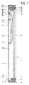
- Fig. 1 The object according to Fig. 1 is designated 1 in its entirety. It particularly is a window, which is rotatable 180° about a horizontal spindle, but it can also be a door.
- the mounting can of course be such, that the rotation is done about a vertical spindle.
- a frame 2 is shown and a casement 3, which surrounds the frame.
- the frame is provided in its lower part in its side pieces 4 with a locking device 5, e.g. an espagnolet device, which includes a handle (not shown) on the inner side of the lower piece of the frame.
- the casement is provided with a raised portion 6 on all sides, which is directed towards the center of the casement, with a stop edge 7, which faces and is designed for the frame, along which stop edge weather strips 51, known per se, can be fastened.
- a swinging armature 8 is shown, known per se, which comprises an array of bars, three of which 9, 10 and 11 are visible.
- a pivot 12 is mounted, which constitutes the axis of rotation for the frame.
- Such armatures 8 are mirror-symmetrically mounted, one on the inner side of each casement side piece 47.
- armatures are introduced on pivots 12 in bearing holes (not shown) in side pieces 4 of the frame and allow the rotation of the frame with as much as 180° in relation to the casement, the armatures being expanded in a scissor-like way, allowing the frame with all its parts, except the one which is positioned uppermost in the closing position, to be removed from the casement in order to, when the rotation has been completed, contact, with its lower portion, the upper casement portion.
- the armatures are introduced in recesses 13 in casement side pieces 47.
- Fig.1 slider fixtures 15 according to the invention are introduced in the upper ends of frame side pieces 4, suitably in shape-complementary recesses 14.
- slider fixtures are mounted mutually mirror-symmetrically in relation to the frame and comprise a preferably circular base plate 16 which, however, is cut in its upper portion in a chord-like way and suitably is positioned with its chord side 17 in the same plane as upper side 18 of the uppermost piece.
- Recesses 14 can be made in a simple and quick fashion in one work operation, namely by providing side pieces 4 before the assemblying of the frame or the finished frame with cuts.
- the base plates are close to their periphery provided with holes 19, e.g. three counterbored holes, which e.g. can be positioned at the same mutual angular distance and at the same distance from the center and recieve fastening screws 20 provided with recessed heads, by means of which fastening screws the slider fixtures are firmly and most durably fastened in the frame.
- the outer side of the slider fixtures can coincide with the outer side of the side pieces, but they suitably are positioned slightly recessed in the same. The advantage of such a design will be explained in the following text.
- a swinging arm 22 is pivotally fastened centrally in each base plate by means of a spindle 21 and is positioned in a plane-parallel way on the outside of the base plate with its plate-like head portion 23 and protrudes laterally slightly outside the same and is in this area bent 90° and forms a comparatively short slider body 24, which is guided in a groove 25 in the casement side pieces, which groove runs parallel to raised portions 6.
- Fastening end 26 of swinging arms 22 is suitably slightly displaced in parallel, e.g. 1-2 mm, in relation to head portion 23, which is easy to accomplish by means of percussion forming or the like.
- a roughly round end is formed, which centrally is provided with a bearing hole 27, through which said spindle 21 is introduced, which suitably is a rivet, provided in the end, which abuts from the outside fastening end 26, with a head 28, which is comparatively wide, e.g. about 10 mm, and may have a thickness of 1-2 mm.
- the other end of spindle 21 is introduced through a bearing hole 29 in the base plate, which on its rear side is counterbored or widened at 30.
- the spindle is upset by means of a device, e.g. a drift or a punch, after the insertion, this spindle portion expanding and filling counterbore 30 with a head 50 in order to securely fasten the spindle and then also keep together the base plate, the spindle and the swinging arm.
- the spindle suitably is stationary in relation to the base plate and the main portion of the swinging arm is, thanks to said parallel displacement, displaced from the base plate with up to 1-2 mm, which means that only the round ring- or plate-shaped fastening end 26 rotates in relation to the base-plate and the spindle as well as the head and consequently results in a very limited friction. A squeezing or pronounced friction is practically impossible.
- Said parallel displacement also has the advantage of in this way compensating tolerances for recesses 14 and also for swelling and shrinkage respectively of frame and casement wood.
- head 28 abut in a level way against the fastening end, i.e. without any type of counterboring or other weakening but nevertheless make the free main surface of the head be positioned in the same plane as or possibly slightly below the level of the surface of the head portion which is remote from the base plate. In this way it is possible to avoid providing an extra groove for the movements of the head in or along the casement side pieces.
- swinging arm 22 is to be guided and it suitably comprises two lugs 31, which are positioned within the same plane at a distance of a few millimeters from each other and which at their sides are provided with barbs 32.
- These lugs are introduced into a slider shoe 33, which suitably is made of a plastic material and comprises two boxes 34, against the side walls of which said barbs act, the pulling out of the shoe being obstructed or made impossible.
- the shoe has a recessed edge 35, which abuts the surface of main portion 23, which is turned away from the base plate, which means that the insertion end of the shoe is positioned in the same plane as the side of the main portion, which is turned towards the base plate.
- chord 17 does not cut away the entire base plate side in question but leaves centrally a locking shoulder 36, which can have slightly converging short sides 37 and rounded corners 38.
- the locking shoulder should suitably be parallel-displaced in relation to the base plate with a distance of e.g. 1-5 mm, preferably about 2 mm.
- Base line 39 for the displacement can have a distance of a few millimeters from chord side 17.
- the parallel-displacement of the shoulder can simply be done by means of a percussion press. It is turned away from the sliding arm and can also be designed to act as an element, which counteracts a rotation of the base plate, the area around the base line being supported by the upper side of the upper piece of the frame.
- a rotation force would press the shoulder portions around and above the base line towards said upper side.
- the bending, the curving or the parallel-displacement of the shoulder also have advantages as to the manufacturing, the sorting and the assemblying.
- the base plate can, thanks to such a design, which deviates from one single plane, be positioned more easily and in this way always be brought into the correct position.
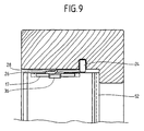
- Recess 14 is roughly so much deeper than the thickness of base plate 16 with what corresponds to the parallel-displacement of main portion 23 in relation to fastening end 26. In this way only a gap width 51 between the frame and the casement is needed, which mainly corresponds to the thickness of said main portion plus manufacturing tolerances and a consideration for swelling and shrinkage respektively of the frame as well as the casement.
- head 28 in a way that is advantageous for the durability, can be made comparatively wide and thick, there is no need whatsoever, thanks to the fearures now described, for any grooves or other cavities to be provided for the head in the casement pieces, which is a clear improvement as compared to already known techniques.
- the fixtures and the other portions according to the invention function in the following way:
- the fixtures are with their slider shoes inserted in the casement grooves, i.e. one at each side of the frame.
- the swinging arm occupies during all positions of the frame always a horizontal position or a position perpendicular to the casement side pieces and the grooves in the same. In this way the shoe slides along all the groove in question during the total movement of the frame and the base plate with the frame rotates in relation to the swinging arm.
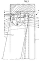
- Fig. 3 the end phase of the closing of the frame is shown.
- the sliding shoe and the swinging arm are thereby moved further upwards and simultaneously the base plate and the frame are swinging counter-clockwise and the locking shoulder starts being inserted into recess 40 in the upper piece of the casement.
- one of sides 37 contacts outwardly turned wall 49 of the recess and forces at the same time the frame to closely abut raised portion 6 of the casement and its weather strip if any or put in another way is this accomplished by using the swinging spindle of the frame of the swinging armature as a swinging center for the frame, when it is closed by e.g. turning the handle and pressing of the frame against the lower casement portion, said swinging spindle reacting and transferring the closing movement like a lever arm to the upper frame arm and finally to the locking shoulder, which in its turn acts to press the upper portion of the frame against the casement.
- the slider shoe is to be inserted in the sliding groove in the casement with a certain allowance in order to secure comparatively friction-free and easy frame movements or that there are allowances whatosever, which are completely evaded due to an interaction bewteen the locking shoulder of the slider fixture and the recess in the upper portion of the casement and other parts and movements according to the description above. Also, in this way an excellent security device in the frame against burglary is obtained.
- the locking shoulder and in this connection the fastening of the base plate in the frame and the fastening of the swinging arm in the casement result in a very substantial resistance against efforts to break the frame by means of e.g. a claw wrench or the like.
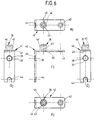
- Base part e corresponds to the base parts shown in Figs. 1-3.
- Base parts a-d, f and g include in the upper corners various recesses, bevels, holes and the like 41, which allow communication between not shown cavities, known per se, e.g. airing or so called turbulence and water drainage grooves and the like in the upper portion and the side pieces of the casement, partly a pressure equalizing and a continuous air circulation and partly a water drainage taking place.
- recesses 41 designed as indent-like cuts, which also function as rotation protection, since edges and corners are formed, which when a rotational force is acting against the base part is effecting the frame wood in and around the recess for the fixture.
- a conventional angular fixture 42 is shown, which is provided with holes 43 and cuts 44 for the insertion of screws (not shown).
- One of the holes is designed to correspond to bearing hole 29 and recess 30 and is designed to receive a spindle, a swinging arm etc., similar to those shown in Figs. 1-4 and described in that connection.
- the fixture is designed to be inserted in recesses, holes or the like at an upper frame corner, one of the holes receiving a swinging spindle with a swinging arm etc. (not shown) according to Figs.
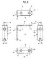
- a locking shoulder 36 is formed, which has functions, which correspond to the locking shoulder according to Figs. 1-5.
- the recess for this shoulder in the upper piece of the casement suitably is adapted as to shape.
- the recess can have any shape, provided an interaction with one wall 49 of the recess is obtained according to Figs. 2 and 3 and the corresponding part of the description.
- Such a fixture is particularly suitable to replace conventional angular fixtures or to be placed in frames with existing recesses, holes or the like or in which the use of fixtures according to Figs. 1-5 is less desirable or for other reasons.
- the fixture according to Fig. 7 is similar to the fixture according to Fig. 8, but locking shoulder 36 has been formed by a punching, cutting or the like 48 in the upper leg, preferably before this leg has been bent away from the vertical leg.
- This fixture design can be done in a simple and inexpensive way.
Landscapes
- Engineering & Computer Science (AREA)
- Mechanical Engineering (AREA)
- Wing Frames And Configurations (AREA)
- Hinges (AREA)
- Specific Sealing Or Ventilating Devices For Doors And Windows (AREA)
Claims (10)
- Fenêtre, porte ou analogues (1) possédant un dormant (2) englobant une pièce supérieure, une pièce inférieure et des pièces latérales (4), ledit dormant étant à même de se déplacer en pivotement entre une position ouverte et une position fermée à l'aide d'armatures oscillantes (8) et étant à même de s'insérer, dans la position fermée, dans un châssis (3) comprenant un élément supérieur, un élément inférieur et des éléments latéraux (47), chacun desdits éléments englobant une portion dressée définissant une face d'arrêt (7) contre laquelle une face correspondante du dormant s'appuie dans la position fermée, le dormant (2) englobant une poignée de manoeuvre agissant sur un dispositif de verrouillage amovible (5) prévu sur ou en position adjacente à la pièce inférieure, lesdites armatures oscillantes (8) comprenant un système de barres (9, 10, 11) reliées les unes aux autres, conçues pour s'élargir à la manière de ciseaux, deux desdites armatures (8) étant montées en symétrie spéculaire sur le châssis, une sur le côté interne de chaque élément latéral (47) de telle sorte qu'une barre de chaque système de barres (9) reliées les unes aux autres supporte ledit dormant, un moyen de verrouillage supplémentaire (36) étant prévu sur la pièce supérieure du dormant pour coopérer avec un évidement (40) pratiqué dans ledit élément supérieur dudit châssis, caractérisée en ce que, en état de marche, la face d'arrêt (7) définie par la portion dressée (6) desdits éléments de châssis est orientée vers l'intérieur dudit châssis, en ce que le dormant est monté de façon à pivoter au-delà de la position ouverte dans une position inversée dans laquelle la surface externe du dormant est orientée vers l'intérieur du châssis et est ainsi accessible de l'intérieur à des fins de nettoyage, en ce que lesdits éléments latéraux (47) dudit châssis (3) sont munis de rainures longitudinales (25) pour guider des supports de coulisseaux (15; 42) montés de manière individuelle et indépendamment desdites armatures oscillantes (8), ainsi qu'en symétrie spéculaire sur le dormant (2) aux extrémités supérieures de ses pièces latérales (4), lesdits supports de coulisseaux (15; 42) englobant des bras oscillants (22) montés en pivotement, des corps de coulisseaux (24) qui viennent s'insérer à des fins de guidage dans lesdites rainures (25) et étant conçus pour retenir la pièce de dormant supérieure dans le châssis lorsque le dormant a oscillé en formant un angle de 180° pour prendre sa position inversée, et en ce que ledit moyen de verrouillage supplémentaire (36) est prévu sur chaque support de coulisseaux (15; 42) sous la forme d'un épaulement de verrouillage faisant saillie conçu pour être pressé, en état de marche au cours de la phase de fermeture du dormant (2), contre la paroi (49) dudit évidement (40) la plus éloignée de la rainure longitudinale correspondante (25) de façon à conférer, en plus d'une protection contre le cambriolage, un effet d'étanchéification supplémentaire à cette portion du dormant contre la portion de châssis correspondante, par transfert via un effet de levier du mouvement de fermeture aux épaulements de verrouillage (36), partant à la pièce de dormant supérieure, pour presser la pièce de dormant supérieure contre le bord d'arrêt (7).
- Fenêtre, porte ou analogues selon la revendication 1, caractérisée en ce que ledit dispositif de verrouillage (5) est monté dans la partie inférieure des pièces latérales (4) du dormant et représente un mécanisme de verrouillage du type à espagnolette englobant ladite poignée de manoeuvre sur le côté interne de la pièce inférieure du dormant (2), en ce que des bandes d'étanchéité (52) sont montées le long dudit bord d'arrêt (7), en ce que ladite première barre (9) susmentionnée de ladite armature oscillante (8) supporte un pivot (12) constituant une broche oscillante du dormant, en ce que lesdits pivots (12) sont insérés dans des trous de paliers dans les pièces latérales (4) du dormant, permettant au dormant d'osciller en formant un angle de 180° par rapport au châssis, en ce que lesdites armatures oscillantes (8) sont insérées dans des évidements (13) pratiqués dans les pièces latérales (47) du châssis (3), et en ce que les supports de coulisseaux (15 ; 42) sont insérés dans des évidements (14) de forme complémentaire dans les extrémités supérieures des pièces latérales (4) du dormant (2).
- Support de coulisseau à utiliser dans une fenêtre, dans une porte ou analogues selon la revendication 1 ou 2, ledit support de coulisseau (15; 42) possédant une plaque de base (16) qui peut être fixée, en état de marche, à une pièce latérale d'un dormant de fenêtre, un bras oscillant (22) étant monté sur la plaque de base pour effectuer une rotation pivotante autour d'un axe (21) qui lui est perpendiculaire, ledit bras oscillant (22) s'étendant en direction radiale par rapport à la plaque de base et portant, en largeur sur son extrémité distale, en formant un angle droit par rapport à cette dernière et se détournant de la plaque de base, un corps de coulisseau (24) destiné à venir s'insérer de manière guidée par coulissement dans une rainure longitudinale correspondante pratiquée dans un des éléments latéraux d'un châssis dans lequel, en état de marche, un dormant de fenêtre est monté en mobilité à l'aide de deux desdits supports de coulisseaux, ledit support de coulisseau définissant en outre un écoulement de verrouillage (36) faisant saillie en direction radiale au-dessus de la plaque de montage, si bien que, lorsque le support de coulisseau est monté, en état de marche, sur une pièce latérale du dormant de fenêtre, l'épaulement de verrouillage (36) fait saillie au-delà d'une pièce supérieure adjacente du dormant de fenêtre de telle sorte que, lorsque le dormant de fenêtre est fermé dans son châssis, l'épaulement de verrouillage peut venir s'insérer par verrouillage dans un évidemment correspondant pratiqué dans un élément supérieur du châssis pour ainsi fixer la portion supérieure du dormant de fenêtre dans son châssis.
- Support de coulisseau selon la revendication 3, caractérisé en ce que ladite plaque de base (16) est de forme généralement circulaire et est partiellement découpée dans sa portion supérieure à la manière d'une membrure, le côté (17) tourné la membrure étant prévu pour venir se disposer dans le même plan que le côté supérieur (18) de la pièce supérieure du dormant, en ce que la plaque de base (16), lorsqu'elle est de forme circulaire, est munie à proximité de sa périphérie, de, par exemple, trois trous traversants à épaulements (19) qui sont disposés à la même distance angulaire réciproque par rapport au centre dans le but de recevoir des vis de fixation (20) munies en particulier de têtes évidées, vis de fixation à l'aide desquelles, les supports de coulisseaux sont fixés dans le dormant, et en ce que le côté externe de la plaque de base est de préférence conçu pour venir se disposer en étant légèrement enfoncé dans le côté externe des pièces latérales en utilisant des évidements (14) de profondeur correspondante pratiqués dans les pièces latérales (4) du dormant.
- Support de coulisseau selon la revendication 3 ou 4, caractérisé en ce que l'extrémité de fixation (26) du bras oscillant (22) du support de coulisseau est pliée, déplacée en parallèle ou analogues par rapport à la partie principale (23) du bras, en permettant un montage plus profond de la partie de base (16) du support de serrage de coulisseaux dans un évidement (14) conçu à cet effet et pratiqué dans le dormant (2), et en permettant l'oscillation de principalement uniquement ladite partie principale avec son épaisseur dans un espace libre (51) ménagé entre le châssis et le dormant.
- Support de coulisseau selon la revendication 5, caractérisé en ce que l'extrémité de fixation (26) du bras oscillant (22) est légèrement déplacée en parallèle, par exemple sur une distance de 1 à 2 mm, par rapport à la partie principale (23), en formant de préférence une extrémité approximativement arrondie qui est munie en son centre d'un trou de palier (27) à travers lequel vient s'insérer ladite broche (21) qui représente de préférence un rivet qui est muni, à son extrémité qui vient buter de l'extérieur contre l'extrémité de fixation (26), d'une tête (28) qui est relativement large, en possédant par exemple une largeur d'environ 10 mm, et qui de préférence possède une épaisseur de 1-2 mm, la broche (21) venant s'insérer avec son autre extrémité, à travers un trou de palier (29) pratiqué dans la plaque de base qui est élargie ou évidée (en 30) sur son côté dorsal, zone dans laquelle la broche est pliée à l'aide d'un dispositif suite à l'insertion, cette partie de broche s'élargissant et remplissant l'évidement (30) avec une tête (50) dans le but de retenir fermement la broche et ainsi de maintenir ensemble la plaque de base, la broche et le bras oscillant, la broche étant de manière appropriée stationnaire par rapport à la plaque de base, et la partie principale du bras oscillant grâce audit déplacement en parallèle, manifestant un déplacement par rapport à la plaque de base s'étendant sur une distance de 1-2 mm, et en ce que la surface principale libre de la tête est positionnée dans le même plan que la surface de la partie principale orientée vers la plaque de base, ou légèrement en-dessous du niveau de ladite surface.
- Support de coulisseau selon l'une quelconque des revendications 3 à 6, caractérisé en ce que le bras oscillant (22) comprend deux ergots (31) qui sont montés dans le même plan à une distance de quelques millimètres l'un de l'autre, lesdits ergots étant munis, sur leurs côtés, de barbes (32) et venant s'insérer dans un sabot coulissant (33) qui est réalisée de manière appropriée en une matière plastique et qui comprend deux boítiers (34) sur les parois latérales desquelles agissent lesdites barbes en rendant difficile voire impossible l'extraction du sabot, et en ce que ledit sabot est muni de préférence d'un bord évidé (35) qui vient buter contre la surface de la partie principale (23) tournée vers la plaque de base, si bien que l'extrémité d'insertion du sabot est disposée dans le même plan que celui du côté de la partie principale tournée vers la plaque de base.
- Support de coulisseau selon l'une quelconque des revendications 3 à 7, caractérisé en ce que ladite découpe en forme de membrure (7) ne s'étend pas sur la totalité du côté de la plaque de base en question mais laisse subsister, en position centrale, ledit épaulement de verrouillage (36) qui est muni de manière appropriée de petits côtés (37) manifestant une légère convergence et de coins arrondis (38) et qui, de manière appropriée, s'est déplacé en parallèle par rapport à la plaque de base sur une distance par exemple de 1 à 5 mm, de préférence, sur une distance d'environ 2 mm, la ligne de base (39) pour le déplacement étant déplacée de quelques millimètres par rapport au côté (17) tourné vers la membrure et le déplacement en parallèle se détournant du bras oscillant.
- Support de coulisseau selon l'une quelconque des revendications 3 à 8, caractérisé en ce que la plaque de base (16) est munie, dans ses coins supérieurs, d'évidements, de chanfreins, de découpes, de trous ou analogues (41) qui permettent d'établir une communication entre des cavités connues en soi, par exemple des rainures d'aération ou des rainure de drainage de la turbulence et de l'eau respectivement, et analogues, dans la pièce supérieure du châssis, et, dans ses pièces latérales, en partie à un équilibrage de la pression et une circulation d'air en continu et en partie un drainage de l'eau pouvant avoir lieu, et/ou lesdits évidements ou analogues (41) ayant également une fonction antirotation en formant des bords et des coins qui, lorsque la plaque de base est soumise à des forces de rotation, sont conçus pour agir sur le bois du dormant dans et autour de l'évidement pour le support de coulisseau.
- Support de coulisseau selon l'une quelconque des revendications 3 à 9, caractérisé en ce que ladite plaque de base (16) comprend un support angulaire (42), principalement déjà connu en soi, qui est muni de trous (43) et/ou de découpes (44), conçus pour que viennent s'y insérer des vis de serrages, un des trous (43) étant conçu sous la forme d'un trou de palier (29) par exemple à l'aide d'un évidemment (30) et étant conçu pour recevoir une broche (21), et en ce qu'un bras oscillant (22) muni d'armatures (42) est conçu pour venir s'insérer dans des évidements, dans des trous ou analogues à un coin supérieur du dormant, un autre trou (43) qui est positionné dans la branche d'insertion de la pièce supérieure du dormant étant conçu pour que vienne s'insérer une vis, un rivet ou analogues (45) orienté vers le haut, autour duquel, de manière appropriée, un manchon ou analogues (46) est monté et fixé via la tête de la vis ou du rivet et est réalisé en une matière métallique ou en une matière plastique et possède de manière appropriée une extrémité libre arrondie conçue sous la forme d'un épaulement de verrouillage (36), l'évidement pour cet épaulement dans la pièce supérieure du châssis possédant de manière appropriée une forme adaptée, ou bien en ce qu'un épaulement de verrouillage (36) est formé en variante à l'aide d'une perforation, d'une découpe ou analogues (48) dans la branche supérieure ou horizontale, de manière appropriée avant de plier ladite branche par rapport à la branche inférieure ou verticale, et/ou en ce que ledit épaulement (36) représente une partie pliée vers le haut à l'extrémité libre de la branche horizontale supérieure, de manière appropriée avec une certaine réduction de la largeur de la branche.
Applications Claiming Priority (3)
| Application Number | Priority Date | Filing Date | Title |
|---|---|---|---|
| SE9202552A SE9202552L (sv) | 1992-09-07 | 1992-09-07 | Ett fönster, en dörr eller liknande och i synnerhet ett härför avsett glidbeslag |
| SE9202552 | 1992-09-07 | ||
| PCT/SE1993/000721 WO1994005881A1 (fr) | 1992-09-07 | 1993-09-06 | Fenetre ou porte et leur montage coulissant |
Publications (3)
| Publication Number | Publication Date |
|---|---|
| EP0659228A1 EP0659228A1 (fr) | 1995-06-28 |
| EP0659228B1 true EP0659228B1 (fr) | 2000-02-02 |
| EP0659228B2 EP0659228B2 (fr) | 2005-07-20 |
Family
ID=20387091
Family Applications (1)
| Application Number | Title | Priority Date | Filing Date |
|---|---|---|---|
| EP93919786A Expired - Lifetime EP0659228B2 (fr) | 1992-09-07 | 1993-09-06 | Fenetre ou porte et leur montage coulissant |
Country Status (6)
| Country | Link |
|---|---|
| EP (1) | EP0659228B2 (fr) |
| DE (1) | DE69327790D1 (fr) |
| DK (1) | DK0659228T4 (fr) |
| NO (1) | NO306824B1 (fr) |
| SE (1) | SE9202552L (fr) |
| WO (1) | WO1994005881A1 (fr) |
Families Citing this family (2)
| Publication number | Priority date | Publication date | Assignee | Title |
|---|---|---|---|---|
| AU728945B3 (en) | 2000-05-31 | 2001-01-18 | Ser Lee Neo | Combined sliding and pivot window assembly |
| EP2372063B1 (fr) | 2010-03-29 | 2018-05-02 | VKR Holding A/S | Ensemble formant fenêtre réversible |
Citations (5)
| Publication number | Priority date | Publication date | Assignee | Title |
|---|---|---|---|---|
| US4616864A (en) * | 1983-10-22 | 1986-10-14 | Hardware & Systems Patents Limited | Fasteners for doors, windows and the like |
| US4616443A (en) * | 1983-10-07 | 1986-10-14 | Sankyo Aluminium Industry Company Limited | Reversible window structure |
| US4860811A (en) * | 1988-02-18 | 1989-08-29 | A/S Spilka Inco Ltd. | Turnable window arrangement |
| GB2216594A (en) * | 1988-03-09 | 1989-10-11 | Interlock Ind Ltd | A window stay or like hardware fitting |
| US5154461A (en) * | 1990-04-27 | 1992-10-13 | Prescott Joseph G | Door secured system |
Family Cites Families (10)
| Publication number | Priority date | Publication date | Assignee | Title |
|---|---|---|---|---|
| US2208802A (en) * | 1939-06-14 | 1940-07-23 | Truscon Steel Co | Window construction |
| US2844850A (en) * | 1956-08-16 | 1958-07-29 | Morris M Eisenberg | Awning window structure and lock therefor |
| NO122614B (fr) * | 1970-06-04 | 1971-07-19 | H Kvasnes | |
| NO137868C (no) * | 1976-11-17 | 1978-05-10 | Harald Kvasnes | Anordning ved vendbart vindu. |
| FR2469540A1 (fr) * | 1979-11-13 | 1981-05-22 | Technal International Sa | Fenetre a projection a un ou plusieurs chassis, a retournement |
| EP0112681B1 (fr) * | 1982-12-24 | 1986-09-24 | Securistyle Limited | Entrebailleurs du type à friction |
| GB8515141D0 (en) * | 1985-06-14 | 1985-07-17 | Securistyle Ltd | Friction supporting stay |
| NO157305C (no) * | 1985-11-25 | 1988-02-24 | Kva Spil Ltd | Anordning ved vindu. |
| GB2246163B (en) * | 1990-05-11 | 1994-09-21 | Cotswold Architect Prod | Stays |
| US5255471A (en) * | 1990-09-07 | 1993-10-26 | Feneseal Limited | Friction stays |
-
1992
- 1992-09-07 SE SE9202552A patent/SE9202552L/xx not_active Application Discontinuation
-
1993
- 1993-09-06 WO PCT/SE1993/000721 patent/WO1994005881A1/fr not_active Ceased
- 1993-09-06 DK DK93919786T patent/DK0659228T4/da active
- 1993-09-06 DE DE69327790T patent/DE69327790D1/de not_active Expired - Lifetime
- 1993-09-06 EP EP93919786A patent/EP0659228B2/fr not_active Expired - Lifetime
-
1995
- 1995-03-03 NO NO950837A patent/NO306824B1/no not_active IP Right Cessation
Patent Citations (5)
| Publication number | Priority date | Publication date | Assignee | Title |
|---|---|---|---|---|
| US4616443A (en) * | 1983-10-07 | 1986-10-14 | Sankyo Aluminium Industry Company Limited | Reversible window structure |
| US4616864A (en) * | 1983-10-22 | 1986-10-14 | Hardware & Systems Patents Limited | Fasteners for doors, windows and the like |
| US4860811A (en) * | 1988-02-18 | 1989-08-29 | A/S Spilka Inco Ltd. | Turnable window arrangement |
| GB2216594A (en) * | 1988-03-09 | 1989-10-11 | Interlock Ind Ltd | A window stay or like hardware fitting |
| US5154461A (en) * | 1990-04-27 | 1992-10-13 | Prescott Joseph G | Door secured system |
Also Published As
| Publication number | Publication date |
|---|---|
| NO306824B1 (no) | 1999-12-27 |
| DK0659228T4 (da) | 2005-08-08 |
| DK0659228T3 (da) | 2000-12-04 |
| WO1994005881A1 (fr) | 1994-03-17 |
| SE9202552D0 (sv) | 1992-09-07 |
| EP0659228B2 (fr) | 2005-07-20 |
| EP0659228A1 (fr) | 1995-06-28 |
| NO950837D0 (no) | 1995-03-03 |
| NO950837L (no) | 1995-03-03 |
| DE69327790D1 (de) | 2000-03-09 |
| SE9202552L (sv) | 1994-03-08 |
Similar Documents
| Publication | Publication Date | Title |
|---|---|---|
| US4824154A (en) | Security lock for double-hung window | |
| EP0868585B1 (fr) | Dispositif de montage pour battant de porte | |
| EP0225058B1 (fr) | Entrebailleurs pour fenêtre | |
| EP0659228B2 (fr) | Fenetre ou porte et leur montage coulissant | |
| EP1290304B1 (fr) | Paumelle pour fenetres pivotantes | |
| CA2374620A1 (fr) | Mecanisme de verrouillage multipoint pour chassis de fenetre | |
| US4078288A (en) | Method for fabricating a door | |
| EP0490928A1 (fr) | Articulation pour portes a deux battants de refrigerateur. | |
| EP3988751B1 (fr) | Structure de montage | |
| GB2110751A (en) | Cockspur fastenings for windows | |
| US5048880A (en) | Door key assembly | |
| US4463976A (en) | Casement windows | |
| CN213477950U (zh) | 欧标槽转宽槽铰链配件及通用滑撑铰链结构 | |
| US20040031204A1 (en) | Door mounting assembly and method | |
| US5682715A (en) | Two piece center mull for multiple door assembly | |
| KR940006900Y1 (ko) | 건물용 점검구의 도어 개폐장치 | |
| CN224002556U (zh) | 一种内置铰链及窗户 | |
| CN219431629U (zh) | 一种具有升降功能的铰链 | |
| EP1061216A2 (fr) | Dispositif de fermeture pour battants de fenêtres | |
| CN223523607U (zh) | 一种玻璃门下门夹结构 | |
| GB2343477A (en) | Door or window security device with two parts having cooperating projections and apertures | |
| SK282756B6 (sk) | Vyklápacie zariadenie na okná, dvere alebo podobne | |
| GB2153903A (en) | Fastening means | |
| EP1457626A2 (fr) | Procédé pour verrouiller le panneau extérieur d'une fenêtre et ferrure de verrrouillage | |
| IE950184A1 (en) | Improvements in cockspur handles |
Legal Events
| Date | Code | Title | Description |
|---|---|---|---|
| PUAI | Public reference made under article 153(3) epc to a published international application that has entered the european phase |
Free format text: ORIGINAL CODE: 0009012 |
|
| 17P | Request for examination filed |
Effective date: 19950307 |
|
| AK | Designated contracting states |
Kind code of ref document: A1 Designated state(s): DE DK GB IE SE |
|
| 17Q | First examination report despatched |
Effective date: 19960531 |
|
| GRAG | Despatch of communication of intention to grant |
Free format text: ORIGINAL CODE: EPIDOS AGRA |
|
| GRAG | Despatch of communication of intention to grant |
Free format text: ORIGINAL CODE: EPIDOS AGRA |
|
| GRAH | Despatch of communication of intention to grant a patent |
Free format text: ORIGINAL CODE: EPIDOS IGRA |
|
| GRAH | Despatch of communication of intention to grant a patent |
Free format text: ORIGINAL CODE: EPIDOS IGRA |
|
| GRAA | (expected) grant |
Free format text: ORIGINAL CODE: 0009210 |
|
| AK | Designated contracting states |
Kind code of ref document: B1 Designated state(s): DE DK GB IE SE |
|
| REF | Corresponds to: |
Ref document number: 69327790 Country of ref document: DE Date of ref document: 20000309 |
|
| PG25 | Lapsed in a contracting state [announced via postgrant information from national office to epo] |
Ref country code: DE Free format text: LAPSE BECAUSE OF FAILURE TO SUBMIT A TRANSLATION OF THE DESCRIPTION OR TO PAY THE FEE WITHIN THE PRESCRIBED TIME-LIMIT Effective date: 20000503 |
|
| REG | Reference to a national code |
Ref country code: IE Ref legal event code: FG4D |
|
| PLBQ | Unpublished change to opponent data |
Free format text: ORIGINAL CODE: EPIDOS OPPO |
|
| PLBI | Opposition filed |
Free format text: ORIGINAL CODE: 0009260 |
|
| REG | Reference to a national code |
Ref country code: DK Ref legal event code: T3 |
|
| PLBF | Reply of patent proprietor to notice(s) of opposition |
Free format text: ORIGINAL CODE: EPIDOS OBSO |
|
| 26 | Opposition filed |
Opponent name: AS SPILKA INDUSTRI Effective date: 20001102 |
|
| PLBF | Reply of patent proprietor to notice(s) of opposition |
Free format text: ORIGINAL CODE: EPIDOS OBSO |
|
| PLBF | Reply of patent proprietor to notice(s) of opposition |
Free format text: ORIGINAL CODE: EPIDOS OBSO |
|
| REG | Reference to a national code |
Ref country code: GB Ref legal event code: IF02 |
|
| PLAY | Examination report in opposition despatched + time limit |
Free format text: ORIGINAL CODE: EPIDOSNORE2 |
|
| PLBC | Reply to examination report in opposition received |
Free format text: ORIGINAL CODE: EPIDOSNORE3 |
|
| 29U | Proceedings interrupted after grant according to rule 142 epc |
Effective date: 20040314 |
|
| 29W | Proceedings resumed after grant [after interruption of proceedings according to rule 142 epc] |
Effective date: 20040813 |
|
| PUAH | Patent maintained in amended form |
Free format text: ORIGINAL CODE: 0009272 |
|
| STAA | Information on the status of an ep patent application or granted ep patent |
Free format text: STATUS: PATENT MAINTAINED AS AMENDED |
|
| 27A | Patent maintained in amended form |
Effective date: 20050720 |
|
| AK | Designated contracting states |
Kind code of ref document: B2 Designated state(s): DE DK GB IE SE |
|
| REG | Reference to a national code |
Ref country code: DK Ref legal event code: T4 |
|
| REG | Reference to a national code |
Ref country code: SE Ref legal event code: RPEO |
|
| REG | Reference to a national code |
Ref country code: GB Ref legal event code: 732E |
|
| PGFP | Annual fee paid to national office [announced via postgrant information from national office to epo] |
Ref country code: DK Payment date: 20110817 Year of fee payment: 19 |
|
| PGFP | Annual fee paid to national office [announced via postgrant information from national office to epo] |
Ref country code: IE Payment date: 20120821 Year of fee payment: 20 Ref country code: SE Payment date: 20120709 Year of fee payment: 20 Ref country code: GB Payment date: 20120828 Year of fee payment: 20 |
|
| REG | Reference to a national code |
Ref country code: DK Ref legal event code: EUP |
|
| REG | Reference to a national code |
Ref country code: GB Ref legal event code: PE20 Expiry date: 20130905 |
|
| REG | Reference to a national code |
Ref country code: SE Ref legal event code: EUG |
|
| PG25 | Lapsed in a contracting state [announced via postgrant information from national office to epo] |
Ref country code: GB Free format text: LAPSE BECAUSE OF EXPIRATION OF PROTECTION Effective date: 20130905 |
|
| REG | Reference to a national code |
Ref country code: IE Ref legal event code: MK9A |
|
| PG25 | Lapsed in a contracting state [announced via postgrant information from national office to epo] |
Ref country code: IE Free format text: LAPSE BECAUSE OF EXPIRATION OF PROTECTION Effective date: 20130906 |