EP0659236B1 - Selbstreinigende hin- und herbewegende rotierende vorrichtung - Google Patents
Selbstreinigende hin- und herbewegende rotierende vorrichtung Download PDFInfo
- Publication number
- EP0659236B1 EP0659236B1 EP93921320A EP93921320A EP0659236B1 EP 0659236 B1 EP0659236 B1 EP 0659236B1 EP 93921320 A EP93921320 A EP 93921320A EP 93921320 A EP93921320 A EP 93921320A EP 0659236 B1 EP0659236 B1 EP 0659236B1
- Authority
- EP
- European Patent Office
- Prior art keywords
- sleeve
- piston
- rotating
- reciprocating pump
- pump according
- Prior art date
- Legal status (The legal status is an assumption and is not a legal conclusion. Google has not performed a legal analysis and makes no representation as to the accuracy of the status listed.)
- Expired - Lifetime
Links
- 238000004140 cleaning Methods 0.000 title description 3
- 239000012530 fluid Substances 0.000 claims abstract description 61
- 238000007790 scraping Methods 0.000 claims abstract description 37
- 239000000463 material Substances 0.000 claims abstract description 24
- PNEYBMLMFCGWSK-UHFFFAOYSA-N Alumina Chemical compound [O-2].[O-2].[O-2].[Al+3].[Al+3] PNEYBMLMFCGWSK-UHFFFAOYSA-N 0.000 claims description 13
- OYPRJOBELJOOCE-UHFFFAOYSA-N Calcium Chemical compound [Ca] OYPRJOBELJOOCE-UHFFFAOYSA-N 0.000 claims description 13
- UIIMBOGNXHQVGW-UHFFFAOYSA-M Sodium bicarbonate Chemical compound [Na+].OC([O-])=O UIIMBOGNXHQVGW-UHFFFAOYSA-M 0.000 claims description 13
- 239000011575 calcium Substances 0.000 claims description 13
- 229910052791 calcium Inorganic materials 0.000 claims description 13
- 239000012633 leachable Substances 0.000 claims description 8
- 238000004891 communication Methods 0.000 claims description 4
- 150000001875 compounds Chemical class 0.000 claims description 3
- 239000012670 alkaline solution Substances 0.000 claims 1
- 239000000243 solution Substances 0.000 claims 1
- 239000000126 substance Substances 0.000 abstract description 20
- 238000006243 chemical reaction Methods 0.000 abstract description 7
- 230000002459 sustained effect Effects 0.000 abstract description 3
- 238000005086 pumping Methods 0.000 description 16
- 239000000919 ceramic Substances 0.000 description 7
- VTYYLEPIZMXCLO-UHFFFAOYSA-L Calcium carbonate Chemical compound [Ca+2].[O-]C([O-])=O VTYYLEPIZMXCLO-UHFFFAOYSA-L 0.000 description 6
- 229910000030 sodium bicarbonate Inorganic materials 0.000 description 6
- 235000017557 sodium bicarbonate Nutrition 0.000 description 6
- 238000002386 leaching Methods 0.000 description 5
- 238000004519 manufacturing process Methods 0.000 description 4
- 230000008901 benefit Effects 0.000 description 3
- 229910000019 calcium carbonate Inorganic materials 0.000 description 3
- CPLXHLVBOLITMK-UHFFFAOYSA-N Magnesium oxide Chemical compound [Mg]=O CPLXHLVBOLITMK-UHFFFAOYSA-N 0.000 description 2
- UIIMBOGNXHQVGW-DEQYMQKBSA-M Sodium bicarbonate-14C Chemical compound [Na+].O[14C]([O-])=O UIIMBOGNXHQVGW-DEQYMQKBSA-M 0.000 description 2
- FAPWRFPIFSIZLT-UHFFFAOYSA-M Sodium chloride Chemical compound [Na+].[Cl-] FAPWRFPIFSIZLT-UHFFFAOYSA-M 0.000 description 2
- 239000000654 additive Substances 0.000 description 2
- 229910052729 chemical element Inorganic materials 0.000 description 2
- 238000006073 displacement reaction Methods 0.000 description 2
- 238000005516 engineering process Methods 0.000 description 2
- 239000002244 precipitate Substances 0.000 description 2
- VYZAMTAEIAYCRO-UHFFFAOYSA-N Chromium Chemical compound [Cr] VYZAMTAEIAYCRO-UHFFFAOYSA-N 0.000 description 1
- DGAQECJNVWCQMB-PUAWFVPOSA-M Ilexoside XXIX Chemical compound C[C@@H]1CC[C@@]2(CC[C@@]3(C(=CC[C@H]4[C@]3(CC[C@@H]5[C@@]4(CC[C@@H](C5(C)C)OS(=O)(=O)[O-])C)C)[C@@H]2[C@]1(C)O)C)C(=O)O[C@H]6[C@@H]([C@H]([C@@H]([C@H](O6)CO)O)O)O.[Na+] DGAQECJNVWCQMB-PUAWFVPOSA-M 0.000 description 1
- GRYLNZFGIOXLOG-UHFFFAOYSA-N Nitric acid Chemical compound O[N+]([O-])=O GRYLNZFGIOXLOG-UHFFFAOYSA-N 0.000 description 1
- ZLMJMSJWJFRBEC-UHFFFAOYSA-N Potassium Chemical compound [K] ZLMJMSJWJFRBEC-UHFFFAOYSA-N 0.000 description 1
- RTAQQCXQSZGOHL-UHFFFAOYSA-N Titanium Chemical compound [Ti] RTAQQCXQSZGOHL-UHFFFAOYSA-N 0.000 description 1
- 229910010293 ceramic material Inorganic materials 0.000 description 1
- 229910052804 chromium Inorganic materials 0.000 description 1
- 239000011651 chromium Substances 0.000 description 1
- 230000001112 coagulating effect Effects 0.000 description 1
- 230000007797 corrosion Effects 0.000 description 1
- 238000005260 corrosion Methods 0.000 description 1
- 229910052593 corundum Inorganic materials 0.000 description 1
- 230000001419 dependent effect Effects 0.000 description 1
- 238000002405 diagnostic procedure Methods 0.000 description 1
- 239000012770 industrial material Substances 0.000 description 1
- 239000007788 liquid Substances 0.000 description 1
- 239000000395 magnesium oxide Substances 0.000 description 1
- 239000000203 mixture Substances 0.000 description 1
- 229910017604 nitric acid Inorganic materials 0.000 description 1
- 239000004033 plastic Substances 0.000 description 1
- 229920003023 plastic Polymers 0.000 description 1
- 239000011591 potassium Substances 0.000 description 1
- 229910052700 potassium Inorganic materials 0.000 description 1
- 239000011734 sodium Substances 0.000 description 1
- 229910052708 sodium Inorganic materials 0.000 description 1
- 239000011780 sodium chloride Substances 0.000 description 1
- 239000007787 solid Substances 0.000 description 1
- 229910052719 titanium Inorganic materials 0.000 description 1
- 239000010936 titanium Substances 0.000 description 1
- XLYOFNOQVPJJNP-UHFFFAOYSA-N water Substances O XLYOFNOQVPJJNP-UHFFFAOYSA-N 0.000 description 1
- 229910001845 yogo sapphire Inorganic materials 0.000 description 1
Images
Classifications
-
- F—MECHANICAL ENGINEERING; LIGHTING; HEATING; WEAPONS; BLASTING
- F16—ENGINEERING ELEMENTS AND UNITS; GENERAL MEASURES FOR PRODUCING AND MAINTAINING EFFECTIVE FUNCTIONING OF MACHINES OR INSTALLATIONS; THERMAL INSULATION IN GENERAL
- F16K—VALVES; TAPS; COCKS; ACTUATING-FLOATS; DEVICES FOR VENTING OR AERATING
- F16K41/00—Spindle sealings
-
- F—MECHANICAL ENGINEERING; LIGHTING; HEATING; WEAPONS; BLASTING
- F04—POSITIVE - DISPLACEMENT MACHINES FOR LIQUIDS; PUMPS FOR LIQUIDS OR ELASTIC FLUIDS
- F04B—POSITIVE-DISPLACEMENT MACHINES FOR LIQUIDS; PUMPS
- F04B53/00—Component parts, details or accessories not provided for in, or of interest apart from, groups F04B1/00 - F04B23/00 or F04B39/00 - F04B47/00
- F04B53/14—Pistons, piston-rods or piston-rod connections
- F04B53/143—Sealing provided on the piston
-
- F—MECHANICAL ENGINEERING; LIGHTING; HEATING; WEAPONS; BLASTING
- F04—POSITIVE - DISPLACEMENT MACHINES FOR LIQUIDS; PUMPS FOR LIQUIDS OR ELASTIC FLUIDS
- F04B—POSITIVE-DISPLACEMENT MACHINES FOR LIQUIDS; PUMPS
- F04B7/00—Piston machines or pumps characterised by having positively-driven valving
- F04B7/04—Piston machines or pumps characterised by having positively-driven valving in which the valving is performed by pistons and cylinders coacting to open and close intake or outlet ports
- F04B7/06—Piston machines or pumps characterised by having positively-driven valving in which the valving is performed by pistons and cylinders coacting to open and close intake or outlet ports the pistons and cylinders being relatively reciprocated and rotated
-
- F—MECHANICAL ENGINEERING; LIGHTING; HEATING; WEAPONS; BLASTING
- F05—INDEXING SCHEMES RELATING TO ENGINES OR PUMPS IN VARIOUS SUBCLASSES OF CLASSES F01-F04
- F05C—INDEXING SCHEME RELATING TO MATERIALS, MATERIAL PROPERTIES OR MATERIAL CHARACTERISTICS FOR MACHINES, ENGINES OR PUMPS OTHER THAN NON-POSITIVE-DISPLACEMENT MACHINES OR ENGINES
- F05C2203/00—Non-metallic inorganic materials
- F05C2203/08—Ceramics; Oxides
- F05C2203/0865—Oxide ceramics
- F05C2203/0869—Aluminium oxide
Definitions
- the present invention relates to rotating and reciprocating pumps wherein a piston or shaft moves within a substantially hollow sleeve in a fluidic environment which causes a leachable substance in the piston and/or the sleeve to leach therefrom and coagulate in the gap between the sleeve and the piston.
- the present invention is particularly suitable for reciprocating pumps and shuttle valves formed of materials having leachable components and which operate in environments causing the leachable components to leach out and bind the relatively moving parts.
- piston to sleeve clearances of about 0.00005-0.0002 inches (0.00127 - 0.00508 mm) are preferred for certain pump applications which require very precise volumetric control over a range of differential pressures in order to avoid syphoning through the pump.
- relatively small pressure differentials between the inlet and outlet of a pump can cause leakage of fluid through a pump if the pump is not constructed with tight enough clearances. Even small leakages through the pump are unacceptable for certain applications, e.g. pharmaceutical applications, requiring high degrees of precision.
- the present invention relates to a rotating and reciprocating pump for controlling the movement of a fluid from a fluid source to a fluid outlet comprising:
- the present invention relates to a rotating and reciprocating pump for controlling the movement of a fluid from a fluid source to a fluid outlet comprising:
- the present invention provides an improved cylinder and sleeve combination which specifically utilizes closely positioned moving elements that leach one or more substances upon sustained contact with the subject fluid. Unlike the previous attempts to overcome binding between these moving elements which strived to find materials for the moving elements which were inert with respect to the fluid, the materials of the present invention are utilized with the knowledge that there will be a chemical reaction between these material and the fluid. It is this reaction which induces the leaching of one or more chemical elements and/or compounds from at least one of the moving elements.
- One preferred embodiment of the present invention comprises a pump which utilizes small clearances that were heretofore unacceptably tight for the applications disclosed herein.
- Another preferred embodiment utilizes materials for at least one of the moving elements which allow a substance to leach out of the moving elements as a result of a chemical reaction with the fluid, and the leached substance undergoes a separate reaction with the fluid which causes it to coagulate.
- the various embodiments of the present invention avoid binding of the moving elements which would otherwise naturally occur by providing at least one scraping edge which continuously scrapes away the coagulum forming between these elements.
- the scraping edge is advantageously configured so as not to interfere with the operative movement of these elements.
- the present invention offers advantages that are applicable to a wide assortment of different devices including pumps having pistons which rotate as they reciprocate within a sleeve, shuttle valves which simply reciprocate within a sleeve, as well as simpler designs wherein a shaft simply rotates within the sleeve.
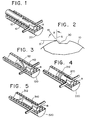
- Figure 1 is a perspective view of the pump of one embodiment of the present invention.
- Figure 2 is a cross-sectional view of Figure 1.
- Figure 3 is a perspective view of a piston of another embodiment of the present invention.
- Figure 4 is a perspective view of a piston of still another embodiment of the present invention.
- Figure 5 is a perspective view of a sleeve of still another embodiment of the present invention.
- the present invention is directed to pumps which utilize a cylinder, such as a piston or shaft, which moves relative to a shaft in a fluidic environment.
- a cylinder such as a piston or shaft
- One embodiment of the present invention comprises a specific group of fluid metering systems for the precise metering of small aliquots of reactive fluids.
- reactive fluids is meant to include fluids which will react with a moving element causing that moving element to leach a coagulable chemical element and/or compound.
- the present invention is unnecessary for previously known pumping applications for which sufficiently inert materials are available for the manufacture of the moving elements, the present invention is particularly suitable for technology driven applications for which sufficiently inert materials are not yet available.
- the present invention is also particularly suitable for systems having a pressure differential, other than the pressure differential created by the pump, between the inlet and outlet of the pump.
- the pressure differential can range from higher than tens of p.s.i. (tens of thousands of Pascals) to as low as several inches (millimeters) of water.
- the applicability of the present invention is dependent upon several factors including the material(s) used to fabricate the moving elements, the chemical relationship between the fluid being pumped and those materials, and the clearance in the gap between the moving elements.
- the terms "gap” and “clearance” refer to the space and the size of that space, respectively, between a piston/shaft and a sleeve.
- these moving elements can not be manufactured and assembled without providing some clearance between the outer surface of the piston and the inner surface of the sleeve.
- the clearance between these relatively moving parts plays a role in the applicability of the present invention since the smaller clearances desired for some applications greatly increases the likelihood that these elements will bind.
- the moving elements of the various embodiments of the present invention are preferably formed with clearances of no more than 0.0005 inches (0.00127 cm), more preferably not greater than 0.0002 inches (0.000508 cm), and most preferably not more than 0.0001 inches (0.000254 cm).
- clearances of no more than 0.0005 inches (0.00127 cm) are suitable for applications requiring the precise metering of reactive fluids.
- the present invention is intended to be used in a fluidic environment wherein a fluid is known to react with at least one of the moving elements causing the moving element to leach a coagulable substance into the gap between the pumping elements.
- One embodiment of the present invention is a pumping system comprising a dimensionally-matched pair of alumina-ceramic pumping elements formed with a clearance of 0.0001 ⁇ 0.00005 inches (0.000254 ⁇ 0.000127 cm) which are utilized to pump a solution of sodium bicarbonate.
- the level of alumina (Al 2 O 3 ) in the alumina-ceramic may range from about 85% to 99.9% and is, in this example, preferably about 99.5 - 99.8 % with the remainder of the ceramic comprising additives such as forms of calcium, magnesia, titanium, chromium, sodium and potassium.
- the sodium bicarbonate is drawn into the small gap between the pumping elements by capillary action and/or pressure differentials.
- the sodium bicarbonate then reacts with the ceramic and causes the calcium to leach out of the ceramic and into the gap.
- the leached calcium then reacts with the sodium bicarbonate to form insoluble calcium carbonate which precipitates out of the fluid and coagulates within the gap tending to cause the pump to stall.
- the small clearance and reactive nature of the pumping fluid has been found to cause binding and resultant pump failure in this demanding application.
- the present invention overcomes this binding problem by providing at least one scraping edge which continuously scrapes the coagulum from the gap while the moving elements are in motion.
- the moving elements of one embodiment of the present invention are illustrated. These moving elements are suitable for use in a rotating and reciprocating metering pump such as the type disclosed in U.S. Patent No. 5,020,980 to Pinkerton.
- Piston 10 and sleeve 20 are formed of alumina ceramics comprising 99.8% and 99.5% alumina, respectively. The remainder of the ceramic materials comprises additives employed in the manufacture of the ceramics, including at least one form of calcium.
- This piston and sleeve combination comprises a journal portion which functions primarily to support piston 10 within sleeve 20 and a pumping portion where fluid is moved.
- the fluid of this system comprises a solution of sodium bicarbonate, calcium leaches out of the alumina ceramic, upon contact with the sodium bicarbonate, into the gap and forms insoluble calcium carbonate.
- Piston 10 has an outer diameter 0.0001 ⁇ 0.00005 inches (0.000254 ⁇ 0.000127 cm) smaller than the inner diameter of sleeve 20 and is provided with two longitudinal grooves (recesses) 12.
- the ridges of the grooves 12 form scraping edges 15 which together move over at least 80% of the journal portion of the sleeve 20 scraping away any coagulum and preventing that coagulum from accumulating to the extent that it causes binding of the moving elements.
- the scraping edges 15 of this illustrated embodiment are formed with a scraping angle, defined as the internal angle A created by a first line S which extends upwardly from the inner wall of groove 12 and a second line S' drawn tangent to the outer surface of the piston 10 at a point 0.001 inch (0.00254 cm) from scraping edge 15, of almost 90°.
- Other embodiments of the present invention may be formed with scraping angles of different magnitude, for example, smaller scraping angles of 45° to 60°. Scraping angles greater than 90° can also be employed.
- the advantages of the present invention can be achieved with other configurations which provide scraping edges with different scraping angles. While the embodiment of the present invention illustrated in Figures 1 and 2 has a scraping angle of about 90°, the scraping angle can be greater or smaller and is preferably at least 45°, most preferably at least 60°.
- the scraping edge 15 of this illustrated embodiment has been provided in piston 10 since, as stated above, the piston 10 is formed with a greater proportion of alumina, and less calcium, than sleeve 20. Thus the sleeve of this embodiment is expected to leach more calcium than the piston. Since the resulting calcium carbonate formed by the reaction of the leaching calcium substance and the sodium bicarbonate being pumped is the substance which is coagulating, it is believed that it is most preferable to position the scraping edge opposite the surface which is leaching the greatest amount of calcium substance. Therefore, in alternative embodiments of the present invention where the piston is the moving element which is leaching a greater amount of a calcium substance or some other substance, then the scraping edges are preferably provided in the sleeve. While it is also possible to provide both the sleeve and the moving cylinder with scraping edges, this would involve additional cost and manufacturing steps which are not believed necessary in order to overcome the binding problem associated with the leaching substance and the tight clearances of the moving parts.
- Figures 3 and 4 illustrate alternative embodiments of the present invention wherein a piston is provide with grooves (recesses) disposed at different angles relative to the longitudinal axis of the pistons.
- the groove (recess) 112 on piston 110 extends longitudinally as well as circumferentially around the outer surface of piston 110.
- the groove 112 is advantageously positioned relative to the direction of rotation R of piston 110 in order to maximize the area of sleeve 120 covered by the scraping edges 115.
- two grooves (recesses) 212 are positioned circumferentially on shaft 210.
- the pistons and sleeves are formed of the same material described above with respect to the embodiment shown in Figures 1 and 2.
- Figure 5 illustrates an alternative embodiment of the present invention wherein the inner surface of the a sleeve 320 is provided with two grooves (recesses) 312 each of which form scraping edges 315.
- This embodiment of the present invention is particularly suited for applications wherein a piston or cylindrical shaft is formed of a material which will leach a substance when contacted by a reactive fluid during operation of the device, whether the device is a fluid control device, such as a pump or valve, or a bearing on a rotating shaft.
- the various embodiments of the present invention have been described above as being formed of alumina ceramics, other materials which leach a substance upon sustained contact with a reactive fluid, such as certain plastics and other industrial materials utilized in sleeve-cylinder combinations, will also benefit from the present invention.
- the present invention also has applications which utilize fluids other than the sodium bicarbonate mentioned above.
- other fluids such as sodium chloride solutions, Ringer's solution, nitric acid and a host of other fluids, are known to cause a substance to leach from materials which may be used to form one of the moving elements.
Landscapes
- Engineering & Computer Science (AREA)
- General Engineering & Computer Science (AREA)
- Mechanical Engineering (AREA)
- Details Of Reciprocating Pumps (AREA)
- Reciprocating Pumps (AREA)
- Nozzles (AREA)
- Telephone Set Structure (AREA)
- Removal Of Floating Material (AREA)
Claims (21)
- Verdrängerpumpe zur Steuerung der Bewegung eines Fluids von einer Fluidquelle zu einem Fluidauslaß, umfassend:einen im wesentlichen hohlen Zylinder (20);einen Kolben (10), beweglich gestützt mindestens teilweise innerhalb des Zylinders (20), so daß der Zylinder (20) mindestens einen Abschnitt des Kolbens (10) überlappt, wobei der Kolben (10) einen so dimensionierten äußeren Durchmesser aufweist, daß ein Spalt mit einem Zwischenraum von weniger als 0,00127 cm (0,0005 Inches) zwischen dem Kolben (10) und dem Zylinder (20) im Überlappungsbereich bereitgestellt wird;Einrichtungen zur Zuführung eines Fluids, wobei das Fluid mindestens eine Komponente umfaßt, die auf mindestens einer.der Oberflächen des Zylinders (20) und des Kolbens (10) koagulieren wird und den Zwischenraum zwischen dem Zylinder (20) und dem Kolben (10) verringern wird und dazu neigt, den Kolben (10) mit dem Zylinder (20) zu verbinden;wobei der Zylinder (20) einen Steuerabschnitt und einen Lagerabschnitt umfaßt, wobei der Steuerabschnitt mindestens einen Einlaß und mindestens einen Auslaß umfaßt, wobei der Einlaß in Fluidkontakt mit der Zuführungseinrichtung steht;wobei der Kolben (10) weiter umfaßt(a) nicht miteinander verbundene axiale Nute, wobei die axialen Nute schabende Kanten ausbilden, die sich über einen Abschnitt des Lagerabschnittes bewegen, um das Koagulat vom Spalt abzuschaben, oder(b) eine Nut, die sich kontinuierlich entlang ihrer Länge sowohl axial als auch über den Umfang um den Kolben (10) erstreckt, wobei die Nut eine schabende Kante ausbildet, die sich über einen Abschnitt des Steuerabschnittes bewegt, um das Koagulat vom Spalt abzuschaben, oder(c) zwei Nute, die sich entlang ihrer Länge über den Umfang des Kolbens (10) erstrecken, wobei die Nute schabende Kanten ausbilden, die sich über einen Abschnitt des Steuerabschnittes bewegen, um das Koagulat vom Spalt abzuschaben.
- Verdrängerpumpe zur Steuerung der Bewegung eines Fluids von einer Fluidquelle zu einem Fluidauslaß, umfassend:einen im wesentlichen hohlen Zylinder (320);einen Kolben (310), beweglich gestützt mindestens teilweise innerhalb des Zylinders (320), so daß der Zylinder (320) mindestens einen Abschnitt des Kolbens (310) überlappt, wobei der Kolben (310) einen so dimensionierten äußeren Durchmesser aufweist, daß ein Spalt mit einem Zwischenraum von weniger als 0,00127 cm (0,0005 Inches) zwischen dem Kolben (310) und dem Zylinder (320) im Überlappungsbereich bereitgestellt wird;Einrichtungen zur Zuführung von Fluid, wobei das Fluid mindestens eine Komponente umfaßt, die auf mindestens einer der Oberflächen des Zylinders (320) und des Kolbens (310) koagulieren wird und den Zwischenraum zwischen dem Zylinder (320) und dem Kolben (310) verringern wird und dazu neigt, den Kolben (310) mit dem Zylinder (320) zu verbinden;wobei der Zylinder (320) einen Steuerabschnitt und einen Lagerabschnitt umfaßt, wobei der Steuerabschnitt mindestens einen Einlaß und mindestens einen Auslaß umfaßt, wobei der Einlaß in Fluidkontakt mit der Zuführungseinrichtung steht;wobei der Zylinder (320) weiter eine Nut oder zwei Nute umfaßt, die (eine) schabende Kante(n) ausbilden, um das Koagulat vom Spalt abzuschaben.
- Verdrängerpumpe gemäß einem der Ansprüche 1 oder 2, wobei der Kolben (10; 310) Aluminiumoxidkeramik umfaßt.
- Verdrängerpumpe gemäß Anspruch 4, wobei im Kolben (10; 310) herauslösbares Material anwesend ist und wobei das herauslösbare Material Calcium umfaßt.
- Verdrängerpumpe gemäß einem der Ansprüche 1 bis 4, wobei der Zylinder (20; 320) eine Aluminiumoxidkeramik umfaßt.
- Verdrängerpumpe gemäß Anspruch 5, wobei das herauslösbare Material im Zylinder (20; 320) anwesend ist und wobei das herauslösbare Material Calcium umfaßt.
- Verdrängerpumpe gemäß einem der Ansprüche 1 bis 6, umfassend mindestens eine separate Ausnehmung, die sich über den gesamten Umfang des Kolbens (10; 310) erstreckt.
- Verdrängerpumpe gemäß einem der Ansprüche 1 bis 7, wobei der Lagerabschnitt des Zylinders (20; 320) keine Spülöffnungen zur Entfernung des Koagulats umfaßt.
- Verdrängerpumpe gemäß einem der Ansprüche 1 bis 8, wobei der Zwischenraum weniger als 0,000508 cm (0,0002 Inches) beträgt.
- Verdrängerpumpe gemäß einem der Ansprüche 1 bis 8, wobei der Zwischenraum weniger als 0,000254 cm (0,0001 Inches) beträgt.
- Verdrängerpumpe gemäß einem der Ansprüche 1 bis 8, wobei der Zwischenraum weniger als 0,000127 cm (0,00005 Inches) beträgt.
- Verdrängerpumpe gemäß einem der Ansprüche 1 bis 11, wobei die schabende Kante sich über mindestens 25% des Lagerabschnittes bewegt.
- Verdrängerpumpe gemäß einem der Ansprüche 1 bis 11, wobei die schabende Kante sich über mindestens 50% des Lagerabschnittes bewegt.
- Verdrängerpumpe gemäß einem der Ansprüche 1 bis 13, wobei die schabende Kante einen Schabwinkel von mindestens 45° bildet.
- Verdrängerpumpe gemäß Anspruch 14, wobei der Schabwinkel mindestens 60° beträgt.
- Verdrängerpumpe gemäß Anspruch 14, wobei der Schabwinkel mindestens 90° beträgt.
- Verdrängerpumpe gemäß Anspruch 14, wobei der Schabwinkel größer als 90° ist.
- Verdrängerpumpe gemäß einem der Ansprüche 1 bis 17, wobei der Zylinder (20; 320) eine Aluminiumoxidkeramik umfaßt, die mindestens 0,02% einer Calcium-enthaltenden Verbindung umfaßt.
- Verdrängerpumpe gemäß einem der Ansprüche 1 bis 18, wobei das Fluid eine alkalische Lösung umfaßt.
- Verdrängerpumpe gemäß einem der Ansprüche 1 bis 19, wobei das Fluid eine Natriumhydrogencarbonatlösung umfaßt.
- Verdrängerpumpe gemäß Anspruch 2, wobei die Nut(e) sich entlang ihrer Länge sowohl axial als auch über den Umfang der längeren Fläche des Zylinders (320) erstreckt (erstrecken).
Applications Claiming Priority (3)
| Application Number | Priority Date | Filing Date | Title |
|---|---|---|---|
| US940085 | 1992-09-03 | ||
| US07/940,085 US5279210A (en) | 1992-09-03 | 1992-09-03 | Self cleaning reciprocating and/or rotating device |
| PCT/US1993/008298 WO1994005910A1 (en) | 1992-09-03 | 1993-08-31 | Self-cleaning reciprocating and/or rotating device |
Publications (2)
| Publication Number | Publication Date |
|---|---|
| EP0659236A1 EP0659236A1 (de) | 1995-06-28 |
| EP0659236B1 true EP0659236B1 (de) | 1999-07-28 |
Family
ID=25474204
Family Applications (1)
| Application Number | Title | Priority Date | Filing Date |
|---|---|---|---|
| EP93921320A Expired - Lifetime EP0659236B1 (de) | 1992-09-03 | 1993-08-31 | Selbstreinigende hin- und herbewegende rotierende vorrichtung |
Country Status (5)
| Country | Link |
|---|---|
| US (2) | US5279210A (de) |
| EP (1) | EP0659236B1 (de) |
| AT (1) | ATE182657T1 (de) |
| DE (1) | DE69325813T2 (de) |
| WO (1) | WO1994005910A1 (de) |
Families Citing this family (16)
| Publication number | Priority date | Publication date | Assignee | Title |
|---|---|---|---|---|
| US5741126A (en) * | 1996-03-01 | 1998-04-21 | Stearns; Stanley D. | Valveless metering pump with crisscrossed passage ways in the piston |
| US5856194A (en) | 1996-09-19 | 1999-01-05 | Abbott Laboratories | Method for determination of item of interest in a sample |
| US5795784A (en) | 1996-09-19 | 1998-08-18 | Abbott Laboratories | Method of performing a process for determining an item of interest in a sample |
| US6224347B1 (en) | 1999-09-13 | 2001-05-01 | The Gorman-Rupp Company | Low volume, high precision, positive displacement pump |
| US6398513B1 (en) | 2000-09-20 | 2002-06-04 | Fluid Management, Inc. | Fluid dispensers |
| US20020107501A1 (en) * | 2001-02-02 | 2002-08-08 | Smith James E. | Weight dependent, automatic filling dosage system and method of using same |
| US20050276705A1 (en) * | 2003-05-27 | 2005-12-15 | Ropintassco 2, Llc. | Positive displacement pump having piston and/or liner with vapor deposited polymer surface |
| US20060037971A1 (en) * | 2004-08-19 | 2006-02-23 | Minard James J | Positive displacement pump |
| US20080187449A1 (en) * | 2007-02-02 | 2008-08-07 | Tetra Laval Holdings & Finance Sa | Pump system with integrated piston-valve actuation |
| US20090157219A1 (en) * | 2007-05-03 | 2009-06-18 | Parker Jr Lance T | Intelligent Sleeve Container for Use in a Controlled Syringe System |
| WO2009076429A2 (en) | 2007-12-10 | 2009-06-18 | Medrad, Inc. | Continuous fluid delivery system and method |
| WO2009120692A2 (en) * | 2008-03-25 | 2009-10-01 | Animal Innovations, Inc. | Syringe mechanism for detecting syringe status |
| CA2758597C (en) * | 2009-04-27 | 2018-07-24 | Animal Innovations, Inc. | Injection syringe plunger valve assembly |
| CN104421441A (zh) * | 2013-08-27 | 2015-03-18 | 山西省霍州市化学工业有限责任公司 | 一种防卡死插板阀装置 |
| ES3030489T3 (en) | 2015-01-09 | 2025-06-30 | Bayer Healthcare Llc | Multiple fluid delivery system with multi-use disposable set and features thereof |
| CN113330214B (zh) * | 2019-01-31 | 2023-04-07 | 京瓷株式会社 | 柱塞泵、输液装置和液相色谱仪 |
Family Cites Families (8)
| Publication number | Priority date | Publication date | Assignee | Title |
|---|---|---|---|---|
| US2791209A (en) * | 1955-05-25 | 1957-05-07 | Richard H Sheppard | Grooved cylinder liner |
| JPS5332336B2 (de) * | 1973-05-24 | 1978-09-07 | ||
| US3923428A (en) * | 1973-06-18 | 1975-12-02 | Western Plaster Equipment Co L | Pumps |
| US4772184A (en) * | 1986-09-16 | 1988-09-20 | Laing Karsten A | Piston pump for abrasive conveyances |
| US4846051A (en) * | 1988-02-23 | 1989-07-11 | Ford Motor Company | Uncooled oilless internal combustion engine having uniform gas squeeze film lubrication |
| US4955284A (en) * | 1989-02-27 | 1990-09-11 | Ingersoll-Rand Company | Piston having ceramic parts |
| US5020980A (en) * | 1990-01-05 | 1991-06-04 | Dennis Pinkerton | Valveless, positive displacement pump including hinge for angular adjustment |
| US5158441A (en) * | 1991-04-15 | 1992-10-27 | Baxter International Inc. | Proportioning pump |
-
1992
- 1992-09-03 US US07/940,085 patent/US5279210A/en not_active Ceased
-
1993
- 1993-08-31 WO PCT/US1993/008298 patent/WO1994005910A1/en not_active Ceased
- 1993-08-31 AT AT93921320T patent/ATE182657T1/de not_active IP Right Cessation
- 1993-08-31 DE DE69325813T patent/DE69325813T2/de not_active Expired - Fee Related
- 1993-08-31 EP EP93921320A patent/EP0659236B1/de not_active Expired - Lifetime
-
1996
- 1996-01-17 US US08/587,997 patent/USRE35997E/en not_active Expired - Lifetime
Also Published As
| Publication number | Publication date |
|---|---|
| EP0659236A1 (de) | 1995-06-28 |
| DE69325813D1 (de) | 1999-09-02 |
| WO1994005910A1 (en) | 1994-03-17 |
| US5279210A (en) | 1994-01-18 |
| DE69325813T2 (de) | 2000-03-09 |
| USRE35997E (en) | 1998-12-22 |
| ATE182657T1 (de) | 1999-08-15 |
Similar Documents
| Publication | Publication Date | Title |
|---|---|---|
| USRE35997E (en) | Self cleaning reciprocating and/or rotating device | |
| US20040241023A1 (en) | Positive displacement pump having piston and/or liner with vapor deposited polymer surface | |
| EP0686768B1 (de) | Zylinderkopf einer Verdrängerpumpe | |
| EP1183470B1 (de) | Drehkolbenpumpe | |
| KR0160947B1 (ko) | 다중 포트로 유출시키는 펌프 | |
| US11105321B2 (en) | Plunger pump having a rotatable plunger with cut face disposed in a cylinder wherein the cylinder includes a main body and a spacer section with the spacer section having a greater length in an axial direction than the maximum stroke length of the plunger | |
| US20160123312A1 (en) | Fluid Pump Having Liquid Reservoir and Modified Pressure Relief Slot | |
| EP1041320A3 (de) | Pumpe | |
| US20050276705A1 (en) | Positive displacement pump having piston and/or liner with vapor deposited polymer surface | |
| US8864475B2 (en) | Pump with wash flow path for washing displacement piston and seal | |
| US20070256556A1 (en) | Pump having double reverse seal to eliminate leaking and binding | |
| EP0856666B1 (de) | Flüssigkeitsabgabepumpe und Verfahren zu ihrer Kontrolle | |
| CA1242930A (en) | Pump and system employing said pump | |
| US5163824A (en) | Rubber-geared pump with shaftless gear | |
| US6375435B2 (en) | Static cam seal for variable displacement vane pump | |
| EP4127478B1 (de) | Flüssigkeitspumpe mit druckentlastungspfad | |
| JP2002349424A (ja) | 印刷機用ポンプ | |
| JPH11210616A (ja) | アキシアルピストン型ポンプ | |
| US4772184A (en) | Piston pump for abrasive conveyances | |
| KR102861444B1 (ko) | 유압 펌프 및 건설 기계 | |
| US4946355A (en) | Orbital pump | |
| GB1574610A (en) | Piston-type valves and plunger pumps | |
| SU969960A1 (ru) | Насос | |
| JPH0614479U (ja) | 一軸偏心ねじポンプ | |
| JPH0519579Y2 (de) |
Legal Events
| Date | Code | Title | Description |
|---|---|---|---|
| PUAI | Public reference made under article 153(3) epc to a published international application that has entered the european phase |
Free format text: ORIGINAL CODE: 0009012 |
|
| 17P | Request for examination filed |
Effective date: 19941206 |
|
| AK | Designated contracting states |
Kind code of ref document: A1 Designated state(s): AT CH DE FR GB IT SE |
|
| 17Q | First examination report despatched |
Effective date: 19950802 |
|
| GRAG | Despatch of communication of intention to grant |
Free format text: ORIGINAL CODE: EPIDOS AGRA |
|
| GRAG | Despatch of communication of intention to grant |
Free format text: ORIGINAL CODE: EPIDOS AGRA |
|
| GRAH | Despatch of communication of intention to grant a patent |
Free format text: ORIGINAL CODE: EPIDOS IGRA |
|
| GRAH | Despatch of communication of intention to grant a patent |
Free format text: ORIGINAL CODE: EPIDOS IGRA |
|
| GRAA | (expected) grant |
Free format text: ORIGINAL CODE: 0009210 |
|
| AK | Designated contracting states |
Kind code of ref document: B1 Designated state(s): AT CH DE FR GB IT LI SE |
|
| PG25 | Lapsed in a contracting state [announced via postgrant information from national office to epo] |
Ref country code: SE Free format text: THE PATENT HAS BEEN ANNULLED BY A DECISION OF A NATIONAL AUTHORITY Effective date: 19990728 Ref country code: LI Free format text: LAPSE BECAUSE OF FAILURE TO SUBMIT A TRANSLATION OF THE DESCRIPTION OR TO PAY THE FEE WITHIN THE PRESCRIBED TIME-LIMIT Effective date: 19990728 Ref country code: CH Free format text: LAPSE BECAUSE OF FAILURE TO SUBMIT A TRANSLATION OF THE DESCRIPTION OR TO PAY THE FEE WITHIN THE PRESCRIBED TIME-LIMIT Effective date: 19990728 Ref country code: AT Free format text: LAPSE BECAUSE OF FAILURE TO SUBMIT A TRANSLATION OF THE DESCRIPTION OR TO PAY THE FEE WITHIN THE PRESCRIBED TIME-LIMIT Effective date: 19990728 |
|
| REF | Corresponds to: |
Ref document number: 182657 Country of ref document: AT Date of ref document: 19990815 Kind code of ref document: T |
|
| REG | Reference to a national code |
Ref country code: CH Ref legal event code: EP |
|
| REF | Corresponds to: |
Ref document number: 69325813 Country of ref document: DE Date of ref document: 19990902 |
|
| ITF | It: translation for a ep patent filed | ||
| ET | Fr: translation filed | ||
| REG | Reference to a national code |
Ref country code: CH Ref legal event code: PL |
|
| RBV | Designated contracting states (corrected) |
Designated state(s): AT CH DE FR GB IT LI SE |
|
| PLBE | No opposition filed within time limit |
Free format text: ORIGINAL CODE: 0009261 |
|
| STAA | Information on the status of an ep patent application or granted ep patent |
Free format text: STATUS: NO OPPOSITION FILED WITHIN TIME LIMIT |
|
| 26N | No opposition filed | ||
| PGFP | Annual fee paid to national office [announced via postgrant information from national office to epo] |
Ref country code: FR Payment date: 20000912 Year of fee payment: 8 |
|
| REG | Reference to a national code |
Ref country code: GB Ref legal event code: IF02 |
|
| PG25 | Lapsed in a contracting state [announced via postgrant information from national office to epo] |
Ref country code: FR Free format text: LAPSE BECAUSE OF NON-PAYMENT OF DUE FEES Effective date: 20020430 |
|
| REG | Reference to a national code |
Ref country code: FR Ref legal event code: ST |
|
| PGFP | Annual fee paid to national office [announced via postgrant information from national office to epo] |
Ref country code: GB Payment date: 20020904 Year of fee payment: 10 |
|
| PG25 | Lapsed in a contracting state [announced via postgrant information from national office to epo] |
Ref country code: GB Free format text: LAPSE BECAUSE OF NON-PAYMENT OF DUE FEES Effective date: 20030831 |
|
| GBPC | Gb: european patent ceased through non-payment of renewal fee | ||
| PG25 | Lapsed in a contracting state [announced via postgrant information from national office to epo] |
Ref country code: IT Free format text: LAPSE BECAUSE OF NON-PAYMENT OF DUE FEES;WARNING: LAPSES OF ITALIAN PATENTS WITH EFFECTIVE DATE BEFORE 2007 MAY HAVE OCCURRED AT ANY TIME BEFORE 2007. THE CORRECT EFFECTIVE DATE MAY BE DIFFERENT FROM THE ONE RECORDED. Effective date: 20050831 |
|
| PGFP | Annual fee paid to national office [announced via postgrant information from national office to epo] |
Ref country code: DE Payment date: 20070829 Year of fee payment: 15 |
|
| PG25 | Lapsed in a contracting state [announced via postgrant information from national office to epo] |
Ref country code: DE Free format text: LAPSE BECAUSE OF NON-PAYMENT OF DUE FEES Effective date: 20090303 |