EP0659391A1 - Distributeur pour préportionner du ruban - Google Patents
Distributeur pour préportionner du ruban Download PDFInfo
- Publication number
- EP0659391A1 EP0659391A1 EP94118113A EP94118113A EP0659391A1 EP 0659391 A1 EP0659391 A1 EP 0659391A1 EP 94118113 A EP94118113 A EP 94118113A EP 94118113 A EP94118113 A EP 94118113A EP 0659391 A1 EP0659391 A1 EP 0659391A1
- Authority
- EP
- European Patent Office
- Prior art keywords
- tape
- band
- shaped material
- slot
- cutting
- Prior art date
- Legal status (The legal status is an assumption and is not a legal conclusion. Google has not performed a legal analysis and makes no representation as to the accuracy of the status listed.)
- Granted
Links
- 239000000463 material Substances 0.000 claims abstract description 56
- 239000011505 plaster Substances 0.000 claims abstract description 6
- 239000000853 adhesive Substances 0.000 claims abstract description 5
- 230000001070 adhesive effect Effects 0.000 claims abstract description 5
- 239000011324 bead Substances 0.000 claims abstract description 3
- 230000000149 penetrating effect Effects 0.000 claims 1
- 230000004913 activation Effects 0.000 abstract 1
- 238000001266 bandaging Methods 0.000 abstract 1
- 230000005484 gravity Effects 0.000 description 5
- 230000007257 malfunction Effects 0.000 description 5
- 230000001681 protective effect Effects 0.000 description 5
- 230000015572 biosynthetic process Effects 0.000 description 3
- 230000000694 effects Effects 0.000 description 2
- 230000007246 mechanism Effects 0.000 description 2
- 230000006978 adaptation Effects 0.000 description 1
- 239000000356 contaminant Substances 0.000 description 1
- 238000011161 development Methods 0.000 description 1
- 230000018109 developmental process Effects 0.000 description 1
- 230000003746 surface roughness Effects 0.000 description 1
Images


Classifications
-
- A—HUMAN NECESSITIES
- A61—MEDICAL OR VETERINARY SCIENCE; HYGIENE
- A61F—FILTERS IMPLANTABLE INTO BLOOD VESSELS; PROSTHESES; DEVICES PROVIDING PATENCY TO, OR PREVENTING COLLAPSING OF, TUBULAR STRUCTURES OF THE BODY, e.g. STENTS; ORTHOPAEDIC, NURSING OR CONTRACEPTIVE DEVICES; FOMENTATION; TREATMENT OR PROTECTION OF EYES OR EARS; BANDAGES, DRESSINGS OR ABSORBENT PADS; FIRST-AID KITS
- A61F15/00—Auxiliary appliances for wound dressings; Dispensing containers for dressings or bandages
- A61F15/001—Packages or dispensers for bandages, cotton balls, drapes, dressings, gauze, gowns, sheets, sponges, swabsticks or towels
- A61F15/002—Packages or dispensers for bandages, cotton balls, drapes, dressings, gauze, gowns, sheets, sponges, swabsticks or towels dispensers for web or tape like bandages
-
- Y—GENERAL TAGGING OF NEW TECHNOLOGICAL DEVELOPMENTS; GENERAL TAGGING OF CROSS-SECTIONAL TECHNOLOGIES SPANNING OVER SEVERAL SECTIONS OF THE IPC; TECHNICAL SUBJECTS COVERED BY FORMER USPC CROSS-REFERENCE ART COLLECTIONS [XRACs] AND DIGESTS
- Y10—TECHNICAL SUBJECTS COVERED BY FORMER USPC
- Y10S—TECHNICAL SUBJECTS COVERED BY FORMER USPC CROSS-REFERENCE ART COLLECTIONS [XRACs] AND DIGESTS
- Y10S83/00—Cutting
- Y10S83/955—Cutter edge shiftable to present different portion of edge
-
- Y—GENERAL TAGGING OF NEW TECHNOLOGICAL DEVELOPMENTS; GENERAL TAGGING OF CROSS-SECTIONAL TECHNOLOGIES SPANNING OVER SEVERAL SECTIONS OF THE IPC; TECHNICAL SUBJECTS COVERED BY FORMER USPC CROSS-REFERENCE ART COLLECTIONS [XRACs] AND DIGESTS
- Y10—TECHNICAL SUBJECTS COVERED BY FORMER USPC
- Y10T—TECHNICAL SUBJECTS COVERED BY FORMER US CLASSIFICATION
- Y10T83/00—Cutting
- Y10T83/444—Tool engages work during dwell of intermittent workfeed
- Y10T83/4491—Interlock between tool actuating and work feed means
-
- Y—GENERAL TAGGING OF NEW TECHNOLOGICAL DEVELOPMENTS; GENERAL TAGGING OF CROSS-SECTIONAL TECHNOLOGIES SPANNING OVER SEVERAL SECTIONS OF THE IPC; TECHNICAL SUBJECTS COVERED BY FORMER USPC CROSS-REFERENCE ART COLLECTIONS [XRACs] AND DIGESTS
- Y10—TECHNICAL SUBJECTS COVERED BY FORMER USPC
- Y10T—TECHNICAL SUBJECTS COVERED BY FORMER US CLASSIFICATION
- Y10T83/00—Cutting
- Y10T83/444—Tool engages work during dwell of intermittent workfeed
- Y10T83/463—Work-feed element contacts and moves with work
-
- Y—GENERAL TAGGING OF NEW TECHNOLOGICAL DEVELOPMENTS; GENERAL TAGGING OF CROSS-SECTIONAL TECHNOLOGIES SPANNING OVER SEVERAL SECTIONS OF THE IPC; TECHNICAL SUBJECTS COVERED BY FORMER USPC CROSS-REFERENCE ART COLLECTIONS [XRACs] AND DIGESTS
- Y10—TECHNICAL SUBJECTS COVERED BY FORMER USPC
- Y10T—TECHNICAL SUBJECTS COVERED BY FORMER US CLASSIFICATION
- Y10T83/00—Cutting
- Y10T83/626—Operation of member controlled by means responsive to position of element remote from member [e.g., interlock]
-
- Y—GENERAL TAGGING OF NEW TECHNOLOGICAL DEVELOPMENTS; GENERAL TAGGING OF CROSS-SECTIONAL TECHNOLOGIES SPANNING OVER SEVERAL SECTIONS OF THE IPC; TECHNICAL SUBJECTS COVERED BY FORMER USPC CROSS-REFERENCE ART COLLECTIONS [XRACs] AND DIGESTS
- Y10—TECHNICAL SUBJECTS COVERED BY FORMER USPC
- Y10T—TECHNICAL SUBJECTS COVERED BY FORMER US CLASSIFICATION
- Y10T83/00—Cutting
- Y10T83/748—With work immobilizer
- Y10T83/7487—Means to clamp work
- Y10T83/7493—Combined with, peculiarly related to, other element
- Y10T83/7507—Guide for traveling cutter
-
- Y—GENERAL TAGGING OF NEW TECHNOLOGICAL DEVELOPMENTS; GENERAL TAGGING OF CROSS-SECTIONAL TECHNOLOGIES SPANNING OVER SEVERAL SECTIONS OF THE IPC; TECHNICAL SUBJECTS COVERED BY FORMER USPC CROSS-REFERENCE ART COLLECTIONS [XRACs] AND DIGESTS
- Y10—TECHNICAL SUBJECTS COVERED BY FORMER USPC
- Y10T—TECHNICAL SUBJECTS COVERED BY FORMER US CLASSIFICATION
- Y10T83/00—Cutting
- Y10T83/869—Means to drive or to guide tool
- Y10T83/8821—With simple rectilinear reciprocating motion only
- Y10T83/8822—Edge-to-edge of sheet or web [e.g., traveling cutter]
-
- Y—GENERAL TAGGING OF NEW TECHNOLOGICAL DEVELOPMENTS; GENERAL TAGGING OF CROSS-SECTIONAL TECHNOLOGIES SPANNING OVER SEVERAL SECTIONS OF THE IPC; TECHNICAL SUBJECTS COVERED BY FORMER USPC CROSS-REFERENCE ART COLLECTIONS [XRACs] AND DIGESTS
- Y10—TECHNICAL SUBJECTS COVERED BY FORMER USPC
- Y10T—TECHNICAL SUBJECTS COVERED BY FORMER US CLASSIFICATION
- Y10T83/00—Cutting
- Y10T83/889—Tool with either work holder or means to hold work supply
- Y10T83/896—Rotatable wound package supply
-
- Y—GENERAL TAGGING OF NEW TECHNOLOGICAL DEVELOPMENTS; GENERAL TAGGING OF CROSS-SECTIONAL TECHNOLOGIES SPANNING OVER SEVERAL SECTIONS OF THE IPC; TECHNICAL SUBJECTS COVERED BY FORMER USPC CROSS-REFERENCE ART COLLECTIONS [XRACs] AND DIGESTS
- Y10—TECHNICAL SUBJECTS COVERED BY FORMER USPC
- Y10T—TECHNICAL SUBJECTS COVERED BY FORMER US CLASSIFICATION
- Y10T83/00—Cutting
- Y10T83/929—Tool or tool with support
- Y10T83/9457—Joint or connection
- Y10T83/9473—For rectilinearly reciprocating tool
- Y10T83/9478—Tool is single element reciprocable generally perpendicularly to elongate cutting edge [e.g., shear, etc.]
-
- Y—GENERAL TAGGING OF NEW TECHNOLOGICAL DEVELOPMENTS; GENERAL TAGGING OF CROSS-SECTIONAL TECHNOLOGIES SPANNING OVER SEVERAL SECTIONS OF THE IPC; TECHNICAL SUBJECTS COVERED BY FORMER USPC CROSS-REFERENCE ART COLLECTIONS [XRACs] AND DIGESTS
- Y10—TECHNICAL SUBJECTS COVERED BY FORMER USPC
- Y10T—TECHNICAL SUBJECTS COVERED BY FORMER US CLASSIFICATION
- Y10T83/00—Cutting
- Y10T83/929—Tool or tool with support
- Y10T83/9457—Joint or connection
- Y10T83/9473—For rectilinearly reciprocating tool
- Y10T83/9483—Adjustable
Definitions
- the invention relates to a device for portioning band-shaped material, in particular wound or adhesive plasters, with a device for advancing the band-shaped material from a band receiving device, a deflectable band cutting device and a clamping device which essentially fixes the band-shaped material when the band cutting device is deflected.
- the band-shaped material is conveyed by the feed device through an output slot.
- the slot lies in a horizontal plane above which a knife of the band cutting device lies. If the band cutting device is deflected along a guide, the band-shaped material is cut off with a pulling cut.
- a malfunction in the known device arises in that the user actuates the feed device after he has moved the tape cutting device into its maximum deflection position.
- the knife of the band cutting device is still in the band transport path, the knife prevents the band transport and a band jam can occur below the slot, which impairs the further functionality of the device. Even if corresponding warning notices are given on the device, this type of malfunction occurs again and again since these warning notices are often overlooked.
- the slot must not be too narrow when the band cutting device is deflected.
- the band-shaped material tends to move with the knife of the band-cutting device in its direction when it is cut off because the pulling cut exerts a relatively large force on the band-shaped material transversely to the direction of band transport.
- the invention is therefore based on the object of improving the known device and, in particular, of eliminating the problems mentioned and of allowing the portioning device to be used reliably.
- Such a means according to the invention prevents the inadmissible actuation of the tape feed direction and / or slippage of the tape material when cutting and / or falling of the tape material into the tape take-up device when the feed device is actuated.
- the feed device has a manually operable key with an opening which lies in the knife path of the band cutting device. If the tape cutting device assumes its end position after cutting the tape, the knife as part of the tape cutting device lies in the opening and prevents the button from being pressed down, so that no further tape feed can take place. Only after the tape cutting device has moved away from its end position is the button for actuating the tape feeding device released.
- a slit narrowing means which narrows a tape slot between the tape receiving device and the feed device in such a way that it prevents undesired tape movement against the tape feed direction.
- the formation of the slit narrowing means prevents the band-shaped material from falling back due to its gravity, especially when the band feed device neither touches nor holds the band when it is actuated.
- cams and / or spring elements and / or beads are proposed which are in a slot lie between the tape take-up device and the tape feed direction and have an upper edge which is oriented approximately perpendicular to the tape-shaped material or is arranged at an obtuse angle thereto.
- the slit-narrowing means can be passed through the band-shaped material in the tape transport direction with virtually no resistance, while against the direction of the sliver advancement due to the slit narrowing and the edge formation of the slit-narrowing means, a relapse into the tape receptacle due to gravity is prevented.
- the means for preventing unwanted band movements can be formed by a surface structuring on the side of the clamping device facing the band-shaped material. Due to the surface structuring, the side of the clamping device facing the band-shaped material has sufficient roughness so that the friction between the clamping device and the band-shaped material is increased during cutting. This effectively prevents the strip-shaped material from slipping in the strip cutting direction.
- the surface structuring of the clamping device is preferably formed by teeth which are aligned on the upper edge of the clamping device parallel to the tape feed direction and thus essentially perpendicular to the tape cutting direction. It has been shown that the known effective slot width can be maintained by the formation of the teeth and no damage to the tape caused by cutting through the teeth.
- each of the above-described means for preventing unwanted tape movement considerably improves the functioning of the known device, and that the means for preventing the tape feed device from being actuated when the tape cutting device is deflected, the slit narrowing means and the surface structuring means on the clamping device together create a device which eliminates all the problems inherent in the known prior art.
- the combination of all means improves the functionality considerably and ensures reliable cutting of the band-shaped material and ensures good operational readiness of the device according to the invention.
- the device according to the invention for steering the button of the feed device has first and second slots which are penetrated by projections of the button.
- the angle between the first and second slots is expediently approximately 90 °. Adequate fixation and guidance of the button is achieved.
- the band cutting device has an exchangeable knife which is received by a holder and the knife has at least one opening which can be penetrated by an engagement means which is formed on a fixing means which can be inserted into the holder.
- the device has a protective cover for the dispensing slot, and the slot cover ensures that, when the device is not in use, dirt or contaminants do not enter the slot and to the underlying one can reach band-shaped material and make it unusable or contaminate it.
- FIG. 1 and 2 show a device for portioning band-shaped material with a band receiving device designed as a storage container 1, which forms the lower part of the device.
- the upper part 2 of the device has a band cutting device 61, a discharge opening 4 for the band-shaped material and a button 6 which interacts with a band feed device within the device.
- the band cutting device has a handle 8 which is in the starting position in FIG. 1.
- the upper part 2 of the device is covered with a hinged or liftable cap 3, which has the opening 4 and an outlet 7 for the handle 8.
- a slightly conical groove 11 is provided, which runs obliquely at an angle to the slot 10 for the cobbled path.
- the angle at which this groove extends corresponds to the angle of the outlet 7 from FIG. 1.
- a slide piece 12 is provided, into which a knife 13 can be inserted.
- a circular opening 14 is located centrally in the slider, which can also be conical and into which a corresponding conical part of the grip 8 engages.
- the slot 10 also has a widening 15 in the middle to enable the part of the plaster covering the wound not to be jammed or squeezed during transportation through the slot.
- the pavement is clamped in slot 10 during the cut.
- the part 16 between the slot and the groove 11 is designed as a movable clamping device and is provided with spring elements 17 on the side facing the slot.
- the spring elements can be coil springs or, as shown, finger-like elastic projections which are connected in one piece to the clamping device 62.
- the slider 12 In the idle state, the slider 12 is located within a recess 18 on the side of the clamping device 62 facing away from the slot. When the slider 12 is deflected, it runs onto a higher edge 19 of the part 16 and presses it as a clamping wedge under the pressure of the spring elements 17 for narrowing the slot 10 against a fixed wall 20 of the slot. This will the band piece located in the slot 10 is clamped and the knife can effect the cutting in the pulling cut.
- the side of the clamping device 62 or the part 16 facing the slot 10 has a surface structuring by means of which the surface roughness of the clamping wedge is increased.
- the surface structure of the clamping device is formed by teeth 16 'which are aligned on the upper edge of the clamping block 16 parallel to the tape feed direction.
- the part 16 of the clamping device has a widening 15 in the middle on its side facing the slot 10, the width of which corresponds approximately to the inside of the gauze part of a plaster bandage lying on the wound.
- the part 16 can be exchanged for another part 16 with a different widening width, so that a corresponding adjustment of the part 16 to the width of the gauze part of paving material can be made.
- the adaptation of the widening 15 of the part 16 of the clamping device to the bandwidth or the width of the gauze part of a plaster bandage has advantages when cutting and prevents the gauze part from being unnecessarily squeezed when cutting.
- the guide plate 9 has slots 63a and 63b and 64a and 64b, which, viewed in plan view, are arranged perpendicular to one another.
- the slots are penetrated by corresponding projections 24 'and 24' 'of the button 6, so that the button 6 can only be moved in the vertical direction.
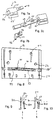
- the feed device for the band-shaped material to be cut is shown. Accordingly, there is a frame 22 pivotally mounted on two axes 21 in the housing wall of the upper part 2 below the guide plate 9. This frame 22 can be pivoted by means of a key 6, which is guided vertically movably in front of the slot 4 or 10, against the pressure of springs 23 which rest below the frame 22.
- the frame 22 has two projections 24 which engage in corresponding cutouts 25 within the button.
- the frame can be pressed down by means of the projections 25 ′ of the button 6 directed towards the band-shaped material, which come to rest over the projections of the frame.
- a driver 28 guided in two longitudinal slots 26 with axes 27, which is exposed when the button 6 is pressed down and, when the button 6 moves upwards, is placed against the material web running in the guide 29 and corresponding to the upward movement of the button slides out a little upwards out of the slots 10 and 4.
- the driver has teeth 28 'in the front region, which is directed towards the band-shaped material, in order to ensure a secure gripping of the band-shaped material.
- two curved tracks 31 and 32 are provided in the interior of the upper part 2, which bear against the axes 27 and guide them in accordance with the upward and downward movement, so that the above-described effect occurs.
- replenishment mechanism described can be formed by another device, for example by a roller or by other lever mechanisms.
- the storage container 1 it is also possible to provide a roller or roller arrangement or another configuration of the tape take-up device.
- the button 6 has an opening 65 in its upper region, which is formed by a notch between the projection 64a to be pointed towards the material web and a projection 66 arranged above it. If the key is not actuated, the notch lies exactly in the cutting line of the knife of the band cutting device and is located where the knife of the band cutting device comes to rest after cutting. Then the knife passes through the notch 65 and prevents the button from being operated. Thus, it cannot happen that the tape feed device is actuated when the tape cutter is in the end position.
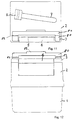
- FIG. 7 shows the knife holder 12 'designed as a slide 12, which has a hole 12' 'through the holder 12', into which the knife 45 and a fixing means 42 for the knife can be inserted.
- the knife has elongated slots or recesses 44 into which a projection 43 of the fixing means 42 can be inserted as an engagement means.
- the fixing means has a protruding edge 46, so that the fixing means cannot be inserted through the hole 12 ′′, but only to a certain depth in the hole. At the same time, the fixing means can wedge the knife in the slider 12, so that the knife is fixed in it and cannot come loose from the holder.
- the knife has two consecutive elongated bores 44, so that the knife, when one side is worn or blunted, can be removed from the holder together with the fixing means and is then turned over so that the still sharp knife area, which was previously inside the holder, is facing outwards.
- the knife can be moved together with the fixing means 42 in the direction of arrow A out of the slider 12.
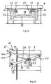
- Fig. 8 is a sectional view along the line B-B in Fig. 2.
- the button 6 and the movable parts of the feed device are omitted in the illustration.
- the middle part 2 has guide slots 58 and 59 which are in alignment with the corresponding slots 63b and 64b.
- the strip material reaches the area of the feed device through a slot 54.
- the reference numeral 52 indicates the holder for the springs shown in FIGS. 5 and 6.
- the receptacles 51 are provided for receiving screws with which the upper part 3 is fastened to the middle part 2.
- the receptacles 51 are arranged in an extension of the screw receptacles 93 shown in FIG. 3.
- slot 54 has slot narrowing means 90, which can have a cross section shown in FIGS. 9 and 10.
- 56 is a base plate of the middle part 2 between the tape take-up device and the feed device.
- the wall opposite the slot narrowing means has a surface structuring 55 ′ which is oriented in the direction of tape advance and which prevents the tape-like material from tilting and slipping sideways.
- the slot 54 is formed by a straight slot wall 70 and a slot narrowing cam 55.
- the cam 55 provides hardly any resistance to the strip material in the feed direction - arrow B - because it continuously reduces the slot width to a predetermined amount.
- the cam 55 has an edge 71 on its upper side, which is perpendicular or perpendicular to the direction of tape transport. Tape material which tends to slide back into the tape receiving device due to gravity due to gravity, is detected by the edge 71 of the cam 55, so that an undesired sliding back into the tape receiving device is prevented.
- FIG. 10 shows an alternative embodiment to a slot narrowing, which is formed by a Y-shaped spring element 57.
- One leg of the Y-shaped spring element made of flexible material is directed towards the slot wall, so that the slot narrows continuously in the tape transport direction.
- the upper edge of the leg directed onto the diaphragm wall has an angle ⁇ to it opposite to the tape feed direction, which angle can also lie in the range between 75 and 175 ° instead of 90 °.
- 11 and 12 show a further advantageous embodiment of the device according to the invention.
- the output slot 4 of the device is covered by a fold-away protective cover 80.
- the cover 80 is attached to the upper part 3 of the device or is integrally formed with it.
- the cover 80 has hinges 82, to which the foldable part 81 of the cover 80 is fastened.
- the flap 81 also has a handle 83.
- the door can be manually moved to a vertical position to expose the output slot. By actuating the tape feed direction and by advancing the tape, however, the flap can also be pushed upwards, so that in the event that the user forgets to fold away the protective cover, the tape-shaped material can still be dispensed.
- the means for guiding the button and / or forming the knife receptacle of the band cutting device and / or forming the protective cover can be designed independently of the means for preventing undesired movement of the band-shaped material and the disclosure of the application is not so may be understood that this Training must always be arranged together with the means for preventing the unwanted belt movement.
- the means for guiding the button 6 and / or the described knife holder of the band cutting device 61 and / or the protective cover 80 fulfills an advantageous function as described above and ensures an improvement of the known device according to G 92 00 572.1.
- the combination of all the different features is possible without any problems and ensures extremely reliable operation of the described device for portioning strip-shaped material 30.
Landscapes
- Health & Medical Sciences (AREA)
- Epidemiology (AREA)
- Engineering & Computer Science (AREA)
- Biomedical Technology (AREA)
- Heart & Thoracic Surgery (AREA)
- Vascular Medicine (AREA)
- Life Sciences & Earth Sciences (AREA)
- Animal Behavior & Ethology (AREA)
- General Health & Medical Sciences (AREA)
- Public Health (AREA)
- Veterinary Medicine (AREA)
- Adhesive Tape Dispensing Devices (AREA)
- Knives (AREA)
Applications Claiming Priority (2)
| Application Number | Priority Date | Filing Date | Title |
|---|---|---|---|
| US15545493A | 1993-11-19 | 1993-11-19 | |
| US155454 | 1993-11-19 |
Publications (2)
| Publication Number | Publication Date |
|---|---|
| EP0659391A1 true EP0659391A1 (fr) | 1995-06-28 |
| EP0659391B1 EP0659391B1 (fr) | 1998-02-18 |
Family
ID=22555501
Family Applications (1)
| Application Number | Title | Priority Date | Filing Date |
|---|---|---|---|
| EP94118113A Expired - Lifetime EP0659391B1 (fr) | 1993-11-19 | 1994-11-17 | Distributeur pour préportionner du ruban |
Country Status (4)
| Country | Link |
|---|---|
| US (1) | US5477761A (fr) |
| EP (1) | EP0659391B1 (fr) |
| DE (1) | DE59405274D1 (fr) |
| NZ (1) | NZ276595A (fr) |
Cited By (1)
| Publication number | Priority date | Publication date | Assignee | Title |
|---|---|---|---|---|
| CN112690953A (zh) * | 2021-01-12 | 2021-04-23 | 周煜晟 | 一种骨科包扎装置 |
Families Citing this family (5)
| Publication number | Priority date | Publication date | Assignee | Title |
|---|---|---|---|---|
| US5904806A (en) * | 1994-10-18 | 1999-05-18 | Tapelicator, Inc. | Tape dispensing applicator and replaceable tape cartridge |
| JP2004312845A (ja) * | 2003-04-04 | 2004-11-04 | Nissan Motor Co Ltd | モータ用ステータ |
| US7066071B2 (en) * | 2003-05-01 | 2006-06-27 | Helen Of Troy Limited | Food slicer |
| US7694615B2 (en) * | 2006-10-31 | 2010-04-13 | Helen Of Troy Limited | Slicer |
| US8851284B2 (en) | 2011-05-18 | 2014-10-07 | Thuban, Inc. | Adhesive bandage dispensing arrangements |
Citations (4)
| Publication number | Priority date | Publication date | Assignee | Title |
|---|---|---|---|---|
| FR2541247A3 (fr) * | 1982-12-08 | 1984-08-24 | Italiana Medicazione Sp Fab | Conditionnement de fibres textiles hydrophiles |
| FR2581915A1 (fr) * | 1985-05-14 | 1986-11-21 | Ruyter Jackie De | Dispositif de couperet pour bandes |
| FR2590829A2 (fr) * | 1985-05-14 | 1987-06-05 | Ruyter Jackie De | Couperet pour bandes avec magasin distributeur |
| FR2606000A2 (fr) * | 1985-05-14 | 1988-05-06 | Ruyter Jackie De | Dispositif de coupe notamment pour pansements |
Family Cites Families (9)
| Publication number | Priority date | Publication date | Assignee | Title |
|---|---|---|---|---|
| US774314A (en) * | 1904-04-04 | 1904-11-08 | John S Ebert | Barber's cabinet. |
| US1249221A (en) * | 1914-01-31 | 1917-12-04 | Calvin H Skeen | Serving apparatus. |
| GB292879A (en) * | 1928-02-14 | 1928-06-28 | Arthur Vivian Thomas Tarr | Improvements in holders for safety razor blades and the like |
| US2251823A (en) * | 1939-06-30 | 1941-08-05 | R C Can Co | Dispensing container |
| US2792885A (en) * | 1954-07-01 | 1957-05-21 | Sidney R Greene | Dispensing device |
| DE2542713C3 (de) * | 1975-09-25 | 1978-10-26 | Scheithauer-Plasticmaschinen, 6146 Alsbach | Vorrichtung zum Querschneiden von Materialbahnen und Stapeln von Material-Stücken |
| DE2755921C2 (de) * | 1977-12-15 | 1982-12-16 | Gerdes Gmbh & Co, 5830 Schwelm | Behälter für mindestens eine zu einer Rolle gewickelte Folienbahn |
| FR2495588A1 (fr) * | 1980-12-05 | 1982-06-11 | Lapalud Cie Emballages Reins | Dispositif pour le deroulement et la coupe d'une feuille de matiere, notamment d'emballage, stockee sous la forme d'un enroulement |
| DE9200572U1 (de) * | 1992-01-18 | 1992-03-19 | Holtsch Metallwarenherstellung Inh. Maria Holtsch, 6204 Taunusstein | Vorrichtung zum handgerechten Darreichen und Abschneiden von bandförmigem Wundpflaster |
-
1994
- 1994-11-14 NZ NZ276595A patent/NZ276595A/en not_active IP Right Cessation
- 1994-11-17 EP EP94118113A patent/EP0659391B1/fr not_active Expired - Lifetime
- 1994-11-17 DE DE59405274T patent/DE59405274D1/de not_active Expired - Fee Related
-
1995
- 1995-04-28 US US08/431,110 patent/US5477761A/en not_active Expired - Lifetime
Patent Citations (4)
| Publication number | Priority date | Publication date | Assignee | Title |
|---|---|---|---|---|
| FR2541247A3 (fr) * | 1982-12-08 | 1984-08-24 | Italiana Medicazione Sp Fab | Conditionnement de fibres textiles hydrophiles |
| FR2581915A1 (fr) * | 1985-05-14 | 1986-11-21 | Ruyter Jackie De | Dispositif de couperet pour bandes |
| FR2590829A2 (fr) * | 1985-05-14 | 1987-06-05 | Ruyter Jackie De | Couperet pour bandes avec magasin distributeur |
| FR2606000A2 (fr) * | 1985-05-14 | 1988-05-06 | Ruyter Jackie De | Dispositif de coupe notamment pour pansements |
Cited By (2)
| Publication number | Priority date | Publication date | Assignee | Title |
|---|---|---|---|---|
| CN112690953A (zh) * | 2021-01-12 | 2021-04-23 | 周煜晟 | 一种骨科包扎装置 |
| CN112690953B (zh) * | 2021-01-12 | 2022-10-25 | 周煜晟 | 一种骨科包扎装置 |
Also Published As
| Publication number | Publication date |
|---|---|
| DE59405274D1 (de) | 1998-03-26 |
| US5477761A (en) | 1995-12-26 |
| NZ276595A (en) | 1997-11-24 |
| EP0659391B1 (fr) | 1998-02-18 |
Similar Documents
| Publication | Publication Date | Title |
|---|---|---|
| EP0955133B1 (fr) | Couteau pour pose | |
| CH637057A5 (de) | Messer mit einer ein- und ausfahrbaren klinge. | |
| EP1790441A1 (fr) | Couteau | |
| DE2401369A1 (de) | Vorrichtung zum verschliessen von blutgefaessen | |
| DE3714302A1 (de) | Schere | |
| DE3640704A1 (de) | Papierlocher | |
| DE3141248C2 (de) | Einrichtung zum Zuführen von Schrauben für einen motorbetriebenen Schraubenzieher | |
| DE1761548A1 (de) | Etikettierapparat | |
| EP0565968B1 (fr) | Dispositif de montage pour attacher des faisceaux de câbles | |
| EP0659391B1 (fr) | Distributeur pour préportionner du ruban | |
| DE3623495A1 (de) | Handgeraet zum anbringen von schildchen | |
| EP0095599A2 (fr) | Dispositif pour transférer un morceau de bande adhésive à un appareil d'encollage du dos d'un bloc de livre ou analogue | |
| DE3644657C2 (fr) | ||
| DE8811711U1 (de) | Zuführ- und Bremsvorrichtung für elastische Bänder | |
| DE1230439B (de) | Vorrichtung zum Zufuehren von zu bedruckendem Band, insbesondere zu Druckmaschinen | |
| EP1231141A1 (fr) | Outil pour appliquer des liens, notamment à des faisceaux de câble | |
| EP1264669A1 (fr) | Dispositif à couper des fruits, des légumes ou analogue | |
| DE649833C (de) | Ausgeber von gummierten Klebestreifen | |
| EP3643465A1 (fr) | Outil manuel de type rabot de coupe | |
| DE2910989C2 (de) | Zangenartiges Werkzeug zum Anbinden der Triebe von Kulturgehölzen | |
| DE10214758A1 (de) | Vorrichtung zum Schneiden von Bodenbelägen | |
| EP0596370B1 (fr) | Arrangement de liage | |
| EP0611634B1 (fr) | Couteau à usages multiples | |
| EP0469461A1 (fr) | Distributeur de ruban adhésif | |
| DE19844448B4 (de) | Kleisterauftragsgerät |
Legal Events
| Date | Code | Title | Description |
|---|---|---|---|
| PUAI | Public reference made under article 153(3) epc to a published international application that has entered the european phase |
Free format text: ORIGINAL CODE: 0009012 |
|
| AK | Designated contracting states |
Kind code of ref document: A1 Designated state(s): DE FR GB IT |
|
| 17P | Request for examination filed |
Effective date: 19951219 |
|
| RAP1 | Party data changed (applicant data changed or rights of an application transferred) |
Owner name: HOLTSCH, MARIA EHEMALS HOLTSCH METALLWARENHERSTELL |
|
| GRAG | Despatch of communication of intention to grant |
Free format text: ORIGINAL CODE: EPIDOS AGRA |
|
| 17Q | First examination report despatched |
Effective date: 19970325 |
|
| GRAG | Despatch of communication of intention to grant |
Free format text: ORIGINAL CODE: EPIDOS AGRA |
|
| GRAH | Despatch of communication of intention to grant a patent |
Free format text: ORIGINAL CODE: EPIDOS IGRA |
|
| GRAH | Despatch of communication of intention to grant a patent |
Free format text: ORIGINAL CODE: EPIDOS IGRA |
|
| GRAA | (expected) grant |
Free format text: ORIGINAL CODE: 0009210 |
|
| AK | Designated contracting states |
Kind code of ref document: B1 Designated state(s): DE FR GB IT |
|
| REF | Corresponds to: |
Ref document number: 59405274 Country of ref document: DE Date of ref document: 19980326 |
|
| ITF | It: translation for a ep patent filed | ||
| ET | Fr: translation filed | ||
| GBT | Gb: translation of ep patent filed (gb section 77(6)(a)/1977) |
Effective date: 19980505 |
|
| PLBE | No opposition filed within time limit |
Free format text: ORIGINAL CODE: 0009261 |
|
| STAA | Information on the status of an ep patent application or granted ep patent |
Free format text: STATUS: NO OPPOSITION FILED WITHIN TIME LIMIT |
|
| 26N | No opposition filed | ||
| PGFP | Annual fee paid to national office [announced via postgrant information from national office to epo] |
Ref country code: DE Payment date: 19990430 Year of fee payment: 5 |
|
| PG25 | Lapsed in a contracting state [announced via postgrant information from national office to epo] |
Ref country code: DE Free format text: LAPSE BECAUSE OF NON-PAYMENT OF DUE FEES Effective date: 20000901 |
|
| REG | Reference to a national code |
Ref country code: GB Ref legal event code: IF02 |
|
| PGFP | Annual fee paid to national office [announced via postgrant information from national office to epo] |
Ref country code: IT Payment date: 20101021 Year of fee payment: 17 |
|
| PGFP | Annual fee paid to national office [announced via postgrant information from national office to epo] |
Ref country code: FR Payment date: 20110826 Year of fee payment: 18 |
|
| REG | Reference to a national code |
Ref country code: FR Ref legal event code: ST Effective date: 20130731 |
|
| PG25 | Lapsed in a contracting state [announced via postgrant information from national office to epo] |
Ref country code: IT Free format text: LAPSE BECAUSE OF NON-PAYMENT OF DUE FEES Effective date: 20121117 |
|
| PG25 | Lapsed in a contracting state [announced via postgrant information from national office to epo] |
Ref country code: FR Free format text: LAPSE BECAUSE OF NON-PAYMENT OF DUE FEES Effective date: 20121130 |
|
| PGFP | Annual fee paid to national office [announced via postgrant information from national office to epo] |
Ref country code: GB Payment date: 20131111 Year of fee payment: 20 |
|
| REG | Reference to a national code |
Ref country code: GB Ref legal event code: PE20 Expiry date: 20141116 |
|
| PG25 | Lapsed in a contracting state [announced via postgrant information from national office to epo] |
Ref country code: GB Free format text: LAPSE BECAUSE OF EXPIRATION OF PROTECTION Effective date: 20141116 |