EP0659459B1 - Filtervorrichtung mit einem Gehäuse und Trägerstruktur zum Festhalten eines Filtermediums - Google Patents
Filtervorrichtung mit einem Gehäuse und Trägerstruktur zum Festhalten eines Filtermediums Download PDFInfo
- Publication number
- EP0659459B1 EP0659459B1 EP94120625A EP94120625A EP0659459B1 EP 0659459 B1 EP0659459 B1 EP 0659459B1 EP 94120625 A EP94120625 A EP 94120625A EP 94120625 A EP94120625 A EP 94120625A EP 0659459 B1 EP0659459 B1 EP 0659459B1
- Authority
- EP
- European Patent Office
- Prior art keywords
- filter
- casing
- filter media
- holes
- filter apparatus
- Prior art date
- Legal status (The legal status is an assumption and is not a legal conclusion. Google has not performed a legal analysis and makes no representation as to the accuracy of the status listed.)
- Expired - Lifetime
Links
- 230000002093 peripheral effect Effects 0.000 claims description 39
- 239000002184 metal Substances 0.000 claims description 5
- 229910052751 metal Inorganic materials 0.000 claims description 5
- 239000000853 adhesive Substances 0.000 claims description 3
- 230000001070 adhesive effect Effects 0.000 claims description 3
- 239000000463 material Substances 0.000 claims description 2
- 125000006850 spacer group Chemical group 0.000 description 5
- 238000002844 melting Methods 0.000 description 4
- 230000008018 melting Effects 0.000 description 4
- 239000003921 oil Substances 0.000 description 4
- 238000007789 sealing Methods 0.000 description 3
- 238000005452 bending Methods 0.000 description 2
- 239000000428 dust Substances 0.000 description 2
- 150000002500 ions Chemical class 0.000 description 2
- 239000010687 lubricating oil Substances 0.000 description 2
- XEEYBQQBJWHFJM-UHFFFAOYSA-N Iron Chemical compound [Fe] XEEYBQQBJWHFJM-UHFFFAOYSA-N 0.000 description 1
- ISWSIDIOOBJBQZ-UHFFFAOYSA-N Phenol Chemical compound OC1=CC=CC=C1 ISWSIDIOOBJBQZ-UHFFFAOYSA-N 0.000 description 1
- 238000010276 construction Methods 0.000 description 1
- 239000004744 fabric Substances 0.000 description 1
- 239000000706 filtrate Substances 0.000 description 1
- 238000001914 filtration Methods 0.000 description 1
- 239000012530 fluid Substances 0.000 description 1
- 239000012535 impurity Substances 0.000 description 1
- 239000004745 nonwoven fabric Substances 0.000 description 1
- 230000035515 penetration Effects 0.000 description 1
- 230000000630 rising effect Effects 0.000 description 1
- XLYOFNOQVPJJNP-UHFFFAOYSA-N water Substances O XLYOFNOQVPJJNP-UHFFFAOYSA-N 0.000 description 1
Images





Classifications
-
- B—PERFORMING OPERATIONS; TRANSPORTING
- B01—PHYSICAL OR CHEMICAL PROCESSES OR APPARATUS IN GENERAL
- B01D—SEPARATION
- B01D35/00—Filtering devices having features not specifically covered by groups B01D24/00 - B01D33/00, or for applications not specifically covered by groups B01D24/00 - B01D33/00; Auxiliary devices for filtration; Filter housing constructions
- B01D35/02—Filters adapted for location in special places, e.g. pipe-lines, pumps, stop-cocks
- B01D35/027—Filters adapted for location in special places, e.g. pipe-lines, pumps, stop-cocks rigidly mounted in or on tanks or reservoirs
- B01D35/0273—Filtering elements with a horizontal or inclined rotation or symmetry axis submerged in tanks or reservoirs
-
- F—MECHANICAL ENGINEERING; LIGHTING; HEATING; WEAPONS; BLASTING
- F01—MACHINES OR ENGINES IN GENERAL; ENGINE PLANTS IN GENERAL; STEAM ENGINES
- F01M—LUBRICATING OF MACHINES OR ENGINES IN GENERAL; LUBRICATING INTERNAL COMBUSTION ENGINES; CRANKCASE VENTILATING
- F01M1/00—Pressure lubrication
- F01M1/10—Lubricating systems characterised by the provision therein of lubricant venting or purifying means, e.g. of filters
- F01M2001/105—Lubricating systems characterised by the provision therein of lubricant venting or purifying means, e.g. of filters characterised by the layout of the purification arrangements
- F01M2001/1078—Lubricating systems characterised by the provision therein of lubricant venting or purifying means, e.g. of filters characterised by the layout of the purification arrangements comprising an oil pick-up tube to oil pump, e.g. strainer
Definitions
- This invention relates to a filter of the type having a casing composed of two casing members.
- FIGS. 11 to 14 illustrate a conventional filter apparatus of the above-described type.
- the filter apparatus is shown upside down for convenience' sake.
- a casing 1 of the shown filter apparatus comprises first and second casing members 2 and 3 each of which has a concavity, as shown in FIGS. 11 and 12.
- the first casing member 2 has a suction port 4 and the second casing member 3 has an exhaust port 5.
- a filter 6 is formed by folding a sheet of filter medium back and has an opening 7 formed so as to correspond to the suction port 4 of the first casing member 2, as shown in FIG. 13.
- the first and second casing members 2, 3 are placed so that the concavities thereof face each other with the filter 6 being enclosed.
- a peripheral edge of the first casing member 2 is put into a peripheral curled portion of the second casing member 3, being held in position so that seal is provided.
- the peripheral edge of the filter 6 is held between the peripheral edges of the first and second casing members 2, 3 except its folded portion. Since portions of the peripheral edges of the casing members 2, 3 holding the peripheral edge of the filter 6 are continuous with those not holding it as shown in FIG. 14, the second casing member 3 is previously formed with a stepped portion 8 so that the folded portion of the filter 6 can be positioned.
- the folded portion of the filter 6 thus need to be positioned with respect to the stepped portion 8 in the above-described filter apparatus. This positioning complicates the control in assembling steps of the filter apparatus. Furthermore, when the casing 1 is formed of a metal, the sealing performance is reduced at the portions of the peripheral edges of the casing members 2, 3 not holding the peripheral edge of the filter 6 therebetween. Additionally, since the filter medium is folded back. through holes formed in the filter 6 to communicate between the interiors of the casing members 2, 3 cannot be located at an optimum position.
- GB-A-2 102 690 shows a filter apparatus in which the filter medium is foldet back, too, so that the above described problems are also present.
- an object of the present invention is to provide an improved filter apparatus where in the sealing performance can be improved and the assembling steps can be simplified.
- the present invention provides a filter apparatus comprising a generally box-shaped casing formed by connecting peripheral edges of first and second casing members each having a concavity, the casing having a suction port and an exhaust port each communicating between the interior of the casing and the exterior thereof and a filter assuming the shape of a bag when disposed in the casing, the filter having an opening, wherein the filter comprises first and second filter media placed one upon the other and having respective peripheries held between substantially the entire peripheral edges of the first and second casing members and wherein the first and second filter media have through holes formed therein respectively and are closely adhered together at peripheral portions of the respective through holes.
- peripheral portions of the through holes of the first and second filter media are closely adhered together, these portions may be bonded together by a adhesive, by melting materials of the first and second filter media, or by cramping the peripheral portions of the through holes of the first and second filter media by an annular metal member.
- the entire peripheral edges of the first and second filter media composing the filter are held between the peripheral edges of the first and second casing members.
- the conventional filter apparatus necessitates a stepped portion for positioning a portion of the peripheral edge of the filter not held between the peripheral edges of the casing members.
- a stepped portion need not be provided in the above-described filter apparatus.
- Both filter media have the respective through holes whose peripheral edges are closely adhered together.
- the interiors of the first and second casing members communicate with each other through the through holes though the filter is interposed between the casing members.
- the invention can provide a filter apparatus which can eliminate the troublesome control in the assembling steps because it does not necessitate such a stepped portion as required in the conventional filter apparatus and which can improve the sealing performance.
- a first casing member 10 and a second casing member 20 have the same contour.
- a peripheral portion of each casing member 10, 20 is bent so that each casing member is formed into the shape of a dish.
- the casing members 10, 20 have flange-like abutting faces 11 and 21 formed by further bending peripheral ends thereof, respectively.
- the peripheral edge of the abutting face 21 of the second casing member 20 is further bent upwardly, thereby providing a curled portion or a margin 21a for receiving the abutting face 11 of the first casing member 10.
- the first casing 10 has an oval suction port 12 formed therein.
- the peripheral edge of the suction port 12 is bent toward a concavity of the first casing 10, thereby providing a cylindrical margin 12a.
- the second casing member 20 has a circular through hole 22 to which a pipe 23 composing an exhaust port 23a is hermetically connected.
- a filter 30 comprises two plate-shaped filter media 31 and 32 which are placed one upon the other.
- the filter media 31, 32 are cut so as to become larger than the contour of each casing member 10, 20.
- the filter media 31, 32 in the flat state are pushed into the interior defined by both casing members 10, 20 such that central portions of the filter media are expanded.
- the expanded portions are referred to as convexities 31a and 32a respectively.
- the filter media 31, 32 have circular through holes 31b and 32b formed in the vicinity of one ends thereof respectively. Overall peripheries of the through holes 31b, 32b are closely adhered circularly to each other, thereby forming separated portions 31c and 32c respectively.
- the filter media 31, 32 are slightly larger than the casing members 10, 20 such that the central portions are expanded slightly.
- the peripheries of the through holes 31b, 32b include portions common to the peripheries of the filter media 31, 32 and portions adjacent to the convex portions 31a, 32a respectively.
- the filter medium 31 has an opening 31d into which the margin 12a can be inserted. Either of the casing members 10, 20 may be located at the upper side of the casing.
- the assembly of the filter apparatus will be described.
- the filter media 31, 32 are separately cut and then placed one upon the other. After the separated portions 31c, 32c are adhered together by melting, the first casing 10 and the filter media 31, 32 are put together at the concave side of the casing 10.
- the cylindrical margin 12a of the first casing 10 is inserted into the opening 31d of the filter medium 31. Thereafter, the margin 12a is pressed so as to be opened so that the periphery of the opening 31d is held between the margin 12a and the first casing 10, whereby the filter medium 31 is hermetically held.
- the pipe 23 is connected to the through hole 22 of the second casing member 20.
- the abutting face 11 of the first casing member 10 is put into the margin 21a rising from the peripheral edge of the abutting face 21 of the second casing 20.
- the peripheral edges of the filter media 31, 32 are interposed between the abutting faces 11, 21 of the respective casing members 10, 20.
- the margin 21a is then pressed toward the abutting face 11 of the first casing 10 in the above-described state. Consequently, the first and second casing members 10, 20 are hermetically cramped together with the peripheral edges of the filter media 31, 32 held between the peripheral edges of the casing members, thereby forming an integral casing 40. Since each filter medium is cut to become larger than the contour of each of the casing members 10, 20, the central portion of each filter medium is expanded in the casing 40.
- the overall peripheral edges of the filter media 31, 32 composing the filter 30 are held between the abutting faces 11, 21 of the respective first and second casing members 10, 20. Furthermore, the overall peripheries of the through holes 31b, 32b of the respective filter media 31, 32 are closely adhered together into the separated portions 31c and 32c. Consequently, the filter 30 assumes the shape of a bag with the convexities 31a, 32a facing each other. Furthermore , the bag-shaped filter 30 is enclosed in the casing 40 having the suction and exhaust ports 12 and 23a with the opening 31d connected to the suction port 12. Accordingly, when the negative pressure is supplied through the exhaust port 23a of the pipe 23 into the casing 40, unclean lubricating oil is drawn through the suction port 12 into the casing 40. Impurities such as iron powder are removed from the lubricating oil as it passes through the filter 30 from the inside to the outside of each filter medium.
- the filter medium 32 faces the side of the second casing 20
- the oil, after having passed through the filter medium 32 is discharged through the exhaust port 23a.
- the oil, after having passed through the other filter medium 31 once comes out to the interior at the side of the first casing member 10. Since the interior at the side of the first casing member 10 communicates with the interior at the side of the second casing member 20 through the holes 31b, 32b of the filter media 31, 32, the oil coming out to the interior at the side of the first casing member 10 is also discharged through the holes 31b, 32b and the exhaust port 23a of the second casing member 20.
- the through holes 31b, 32b are formed in the peripheral port ions of the filter media 31, 32 respectively and the peripheries of the through holes 31b, 32b are closely adhered together, as described above. Consequently, the entire peripheral edges of the filter media 31, 32 can be interposed between the peripheral edges of the first and second casing members 10, 20 with the interior of the first casing member 10 communicating with the interior of the second casing member 20.
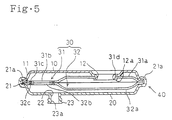
- FIG. 5 illustrates a modified form.
- the suction port 12 and the exhaust port 23a are located away from each other so that the negative pressure from the exhaust port 23a is uniformly applied to the two filter media 31. Consequently, the efficiency of filtration can be improved.
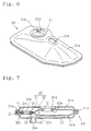
- the peripheries of the through holes 31b, 32b of the filter media 31, 32 are adhered together by melting in the foregoing embodiment, they may be bonded together by an adhesive. Furthermore, the peripheries of the holes 31b, 32b may be cramped by a cylindrical metal member so as to be closely adhered together, as shown as a modified form in FIG. 6. Additionally, a cylindrical metal member may be employed for connection of the opening 31d to the suction port 12, as shown in another modified form in FIG. 7.
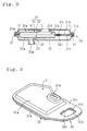
- FIGS. 8 and 9 illustrate a modified form of the filter media 31, 32.
- the filter media 31, 32 each larger than the casing members 10, 20 are pushed into the casing 40 in their flat state such that the central port ion of each filter medium is expanded.
- convex portions 31a and 32a are formed in the filter media 31, 32 by way of stamping respectively.
- the position of the through holes 31b, 32b formed in the filter media 31, 32 in the modified form differs from that of the holes in the foregoing embodiment.
- the position of the through holes 31b, 32b can be determined with some freedom in the present invention.
- each of the convex portions 31a, 32a of the filter media 31, 32 has the contour same as those of the first and second casing members 10, 20 and are formed by way of stamping into the shape of a dish except one end portion.
- the filter media 31, 32 are placed one upon the other with the concave sides thereof facing each other so that a space is defined between the convex portions 31a, 32a.
- the filter media 31, 32 have rectangular through holes 31b and 32b formed in the unstamped portions respectively. Three of four sides of the through holes 31b, 32b extend along the peripheries of the filter media 31, 32 and the other side thereof is adjacent to the convex portions 31a, 32a.
- Each of the filter media 31, 32 is formed by impregnating a nonwoven fabric with phenol and then pressing it. Heat is then applied to the pressed fabric so that it is hardened.
- the filter media 31, 32 are separately cut in the foregoing embodiment, one sheet of filter medium may be folded back.
- the filter medium may be folded back at any portion thereof though the filter medium has a fixed folded portion in the prior art.
- the filter apparatus is used to filterate oil in the foregoing embodiment, it may be used to filtrate other fluids such as water.
- the margin 21a for receiving the peripheral edge of the first casing member 10 is formed by upwardly bending the peripheral edge of the abutting face 21 of the second casing member 20 in the foregoing embodiment.
- a margin 11a may be formed on the peripheral edge of the abutting face 11 of the first casing member 10, instead. These margins 21a, 11a may be used for positioning the casing 40.
- the working efficiency in the assembly of the filter apparatus can be improved when such a margin is formed at any suitable portion in accordance with an order of assembling steps.
- the opening 31d of the filter 30 is connected to the suction port 12 of the second casing member 20 and the negative pressure is applied to the outer face of the filter 30 through the hole 22 as the exhaust port so that the dust is gathered onto the inner surface of the filter 30.
- the through hole 22 may serve as the suction port and the suction port 12 may serve as the exhaust port so that the dust is gathered onto the outer surface of the filter 30.
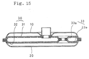
- the bag-shaped filter 30 is rendered narrower when the negative pressure is applied thereto. Spacers need to be provided in the filter 30 so that it is usually maintained in the expanded state.
- FIG. 15 and FIG. 16 One example of the filter apparatus which uses the spacer is illustrated in FIG. 15 and FIG. 16.
- the spacer 33 has almost the same shape as the first and second filters 31, 32, and plurality of penetration holes 33b are formed in the spacer 33.
- the first and second filters 31, 32 place the corresponding pair of first and second spacers 33a, 33b therebetween, and the filters 31, 32 are installed in the casings.
Landscapes
- Chemical & Material Sciences (AREA)
- Chemical Kinetics & Catalysis (AREA)
- Filtering Of Dispersed Particles In Gases (AREA)
- Filtration Of Liquid (AREA)
Claims (5)
- Filtervorrichtung mit einem allgemein schachtelförmigen Gehäuse (40), welches durch Verbinden peripherer Ränder von ersten und zweiten Gehäuseteilen (10, 20) ausgebildet ist, die jeweils einen Hohlraum aufweisen, wobei das Gehäuse (40) eine Ansaugöffnung (12) und eine Ausströmöffnung (23a), welche jeweils das Innere des Gehäuses (40) mit dessen Außenseite verbinden, und einen Filter (30) aufweist, der die Gestalt eines Beutels annimmt, wenn er im Gehäuse (40) angeordnet ist, wobei der Filter (30) eine Öffnung (31d) aufweist, und wobei der Filter (30) ein erstes und zweites Filtermedium (31, 32) enthält, die übereinander angeordnet sind und deren jeweilige Peripherie zwischen im wesentlichen den gesamten peripheren Rändern des ersten und zweiten Gehäuseteiles (10, 20) gehalten werden, und wobei das erste und zweite Filtermedium (31, 32) Durchgangslöcher (31b, 32b) aufweisen, die jeweils darin ausgebildet sind und an den peripheren Abschnitten der jeweiligen Durchgangslöcher (31b, 32b) dicht zusammenhaften.
- Filtervorrichtung nach Anspruch 1, dadurch gekennzeichnet, daß die peripheren Abschnitte der Durchgangslöcher (31b, 32b) des ersten und zweiten Filtermediums (31, 32) durch einen Klebstoff dicht zusammenhaften.
- Filtervorrichtung nach Anspruch 1, dadurch gekennzeichnet, daß die Materialien des ersten und zweiten Filtermediums (31, 32) derart geschmolzen werden, daß die peripheren Abschnitte der Durchgangslöcher (31b, 32b) des ersten und zweiten Filtermediums (31, 32) dicht zusammenhaften.
- Filtervorrichtung nach Anspruch 1, dadurch gekennzeichnet, daß die peripheren Abschnitte der Durchgangslöcher (31b, 32b) des ersten und zweiten Filtermediums (31, 32) durch ein ringförmiges Metallteil derart geklemmt werden, daß sie dicht zusammenhaften.
- Filtervorrichtung nach einem der Ansprüche 1 bis 4, dadurch gekennzeichnet, daß die Öffnung (31d) dazu vorgesehen ist, um entweder mit der Ansaugöffnung (12) oder der Ausströmöffnung (23a) verbindbar zu sein.
Applications Claiming Priority (2)
| Application Number | Priority Date | Filing Date | Title |
|---|---|---|---|
| JP5350077A JP2925907B2 (ja) | 1993-12-27 | 1993-12-27 | フィルタ装置 |
| JP350077/93 | 1993-12-27 |
Publications (3)
| Publication Number | Publication Date |
|---|---|
| EP0659459A2 EP0659459A2 (de) | 1995-06-28 |
| EP0659459A3 EP0659459A3 (de) | 1996-02-21 |
| EP0659459B1 true EP0659459B1 (de) | 1998-06-17 |
Family
ID=18408080
Family Applications (1)
| Application Number | Title | Priority Date | Filing Date |
|---|---|---|---|
| EP94120625A Expired - Lifetime EP0659459B1 (de) | 1993-12-27 | 1994-12-23 | Filtervorrichtung mit einem Gehäuse und Trägerstruktur zum Festhalten eines Filtermediums |
Country Status (4)
| Country | Link |
|---|---|
| US (1) | US5538633A (de) |
| EP (1) | EP0659459B1 (de) |
| JP (1) | JP2925907B2 (de) |
| DE (1) | DE69411138T2 (de) |
Families Citing this family (19)
| Publication number | Priority date | Publication date | Assignee | Title |
|---|---|---|---|---|
| EP0787519A2 (de) * | 1996-02-01 | 1997-08-06 | Toyo Roki Seizo Kabushikikaisha | Filter und Filtermediumeinheit dafür |
| DE19626212C2 (de) * | 1996-06-29 | 1998-04-23 | Luk Fahrzeug Hydraulik | Ölsaugfilter |
| US5853577A (en) * | 1997-09-22 | 1998-12-29 | Spx Corporation | Orbital vibration welded filter |
| DE102005010099B4 (de) * | 2005-03-04 | 2009-07-09 | Ibs Filtran Kunststoff-/ Metallerzeugnisse Gmbh | Filteranordnung mit Filtertasche und Rohrstutzen mit einem kanalartigen Durchlass |
| US7767084B2 (en) * | 2005-07-21 | 2010-08-03 | Nok Corporation | Oil strainer |
| USD551319S1 (en) * | 2006-04-11 | 2007-09-18 | Spx Corporation | Fluid filter |
| DE102007023641B4 (de) * | 2007-05-22 | 2015-04-02 | Ibs Filtran Kunststoff-/ Metallerzeugnisse Gmbh | Ölfiltervorrichtung |
| US8052867B2 (en) * | 2008-04-03 | 2011-11-08 | Filtran Llc | Dual media fluid filter |
| US7998347B2 (en) * | 2008-05-29 | 2011-08-16 | Ford Global Technologies, Llc | Suction filter for automatic transmission fluid |
| JP2010019151A (ja) * | 2008-07-10 | 2010-01-28 | Nifco Inc | 燃料用フィルタ |
| JP5893854B2 (ja) | 2011-06-02 | 2016-03-23 | トヨタ自動車株式会社 | 燃料供給装置 |
| US8372278B1 (en) * | 2012-03-21 | 2013-02-12 | GM Global Technology Operations LLC | Liquid fuel strainer assembly |
| JP6067799B2 (ja) * | 2015-08-05 | 2017-01-25 | トヨタ自動車株式会社 | サブタンク |
| JP6055046B2 (ja) * | 2015-08-05 | 2016-12-27 | トヨタ自動車株式会社 | 燃料供給装置 |
| US11028741B1 (en) | 2020-08-24 | 2021-06-08 | Apq Development, Llc | Oil pick-up assembly |
| USD921045S1 (en) | 2020-08-24 | 2021-06-01 | Apq Development, Llc | Oil pick-up assembly |
| USD916152S1 (en) | 2020-08-24 | 2021-04-13 | Apq Development, Llc | Compression limiter |
| US11078958B1 (en) | 2020-08-24 | 2021-08-03 | Apq Development, Llc | Compression limiter |
| WO2023230319A1 (en) * | 2022-05-26 | 2023-11-30 | Atieva, Inc. | Oil sump system to stabilize oil supply |
Family Cites Families (10)
| Publication number | Priority date | Publication date | Assignee | Title |
|---|---|---|---|---|
| US3014592A (en) * | 1959-10-12 | 1961-12-26 | Chrysler Corp | Transmission oil strainer |
| GB888835A (en) * | 1959-10-12 | 1962-02-07 | Ford Motor Co | Fluid filter assembly and method for making the same |
| US4113627A (en) * | 1976-01-28 | 1978-09-12 | Filtertek, Inc. | Process for making hermetically sealed filter units and filters made thereby |
| US4250039A (en) * | 1979-05-07 | 1981-02-10 | Wire Cloth Products, Inc. | Transmission filter |
| US4402827A (en) * | 1980-07-11 | 1983-09-06 | Sealed Power Corporation | Transmission fluid filter |
| US4450081A (en) * | 1981-07-16 | 1984-05-22 | Sealed Power Corporation | Transmission fluid filter and method of manufacture |
| US4414172A (en) * | 1982-05-21 | 1983-11-08 | Filtertek, Inc. | Process and apparatus for sealing a plurality of filter elements |
| US4600511A (en) * | 1984-08-20 | 1986-07-15 | Allomatic Industries, Inc. | Two-layer fluid filter with spacer |
| US4826598A (en) * | 1985-11-29 | 1989-05-02 | Filtertek, Inc. | Hermetically sealed transmission filter |
| US5049274A (en) * | 1988-01-11 | 1991-09-17 | Filtertek, Inc. | Friction welding process and filter formed thereby |
-
1993
- 1993-12-27 JP JP5350077A patent/JP2925907B2/ja not_active Expired - Fee Related
-
1994
- 1994-12-23 DE DE69411138T patent/DE69411138T2/de not_active Expired - Fee Related
- 1994-12-23 EP EP94120625A patent/EP0659459B1/de not_active Expired - Lifetime
- 1994-12-23 US US08/362,776 patent/US5538633A/en not_active Expired - Lifetime
Also Published As
| Publication number | Publication date |
|---|---|
| DE69411138D1 (de) | 1998-07-23 |
| DE69411138T2 (de) | 1998-10-22 |
| EP0659459A2 (de) | 1995-06-28 |
| US5538633A (en) | 1996-07-23 |
| EP0659459A3 (de) | 1996-02-21 |
| JPH07185224A (ja) | 1995-07-25 |
| JP2925907B2 (ja) | 1999-07-28 |
Similar Documents
| Publication | Publication Date | Title |
|---|---|---|
| EP0659459A2 (de) | Filtervorrichtung mit einem Gehäuse und Trägerstruktur zum Ferthalten eines Filtermediums | |
| EP0145885B1 (de) | Filterelement | |
| KR100196779B1 (ko) | 판형 열교환기판의 가스켓 부착구조 | |
| JPH09173734A (ja) | 一方向にのみ可撓性を有する折りたたみ型フィルタパック | |
| CA2398258A1 (en) | Filter assembly for a vacuum cleaner | |
| JPH0428402B2 (de) | ||
| CA2144000C (en) | A protective-respirator filter | |
| GB2110110A (en) | Air filter | |
| JPH11114348A (ja) | フィルタ装置及びその製造方法 | |
| EP0787519A2 (de) | Filter und Filtermediumeinheit dafür | |
| HK63494A (en) | Gas filter elements | |
| US4604200A (en) | Fluid filter with uniform spacing | |
| JP4506634B2 (ja) | フィルタ及びクリーナ | |
| JP3819175B2 (ja) | 液体容器の通気弁 | |
| IE910296A1 (en) | Cartridge-type filter | |
| JPH09206518A (ja) | フィルタ及び濾材 | |
| JP2000084320A (ja) | 自動変速機用流体フィルタ装置 | |
| JP2747806B2 (ja) | エアクリーナ | |
| EP0113565B1 (de) | Filtereinheit | |
| JP3434582B2 (ja) | フィルタ装置 | |
| JP3857196B2 (ja) | トランスミッション流体用フィルタ | |
| JP2554823B2 (ja) | シール環及び該シール環を有するフィルタプレスの圧搾膜 | |
| JPS6223528Y2 (de) | ||
| JPH0612288Y2 (ja) | 自動変速装置用流体フィルタ装置 | |
| JPS6034330Y2 (ja) | 濾紙エレメント |
Legal Events
| Date | Code | Title | Description |
|---|---|---|---|
| PUAI | Public reference made under article 153(3) epc to a published international application that has entered the european phase |
Free format text: ORIGINAL CODE: 0009012 |
|
| AK | Designated contracting states |
Kind code of ref document: A2 Designated state(s): DE GB |
|
| RIN1 | Information on inventor provided before grant (corrected) |
Inventor name: MURAMATSU, NAOMI Inventor name: KATAGIRI, KEIICHI Inventor name: YAMASHITA, HIROAKI Inventor name: NOGAMI, SHUNICHI Inventor name: KITAJIMA, KYOJI |
|
| PUAL | Search report despatched |
Free format text: ORIGINAL CODE: 0009013 |
|
| AK | Designated contracting states |
Kind code of ref document: A3 Designated state(s): DE GB |
|
| 17P | Request for examination filed |
Effective date: 19960425 |
|
| 17Q | First examination report despatched |
Effective date: 19961008 |
|
| GRAG | Despatch of communication of intention to grant |
Free format text: ORIGINAL CODE: EPIDOS AGRA |
|
| GRAG | Despatch of communication of intention to grant |
Free format text: ORIGINAL CODE: EPIDOS AGRA |
|
| GRAH | Despatch of communication of intention to grant a patent |
Free format text: ORIGINAL CODE: EPIDOS IGRA |
|
| GRAA | (expected) grant |
Free format text: ORIGINAL CODE: 0009210 |
|
| AK | Designated contracting states |
Kind code of ref document: B1 Designated state(s): DE GB |
|
| REF | Corresponds to: |
Ref document number: 69411138 Country of ref document: DE Date of ref document: 19980723 |
|
| PLBE | No opposition filed within time limit |
Free format text: ORIGINAL CODE: 0009261 |
|
| STAA | Information on the status of an ep patent application or granted ep patent |
Free format text: STATUS: NO OPPOSITION FILED WITHIN TIME LIMIT |
|
| 26N | No opposition filed | ||
| REG | Reference to a national code |
Ref country code: GB Ref legal event code: IF02 |
|
| PGFP | Annual fee paid to national office [announced via postgrant information from national office to epo] |
Ref country code: DE Payment date: 20090130 Year of fee payment: 15 |
|
| PGFP | Annual fee paid to national office [announced via postgrant information from national office to epo] |
Ref country code: GB Payment date: 20081219 Year of fee payment: 15 |
|
| GBPC | Gb: european patent ceased through non-payment of renewal fee |
Effective date: 20091223 |
|
| PG25 | Lapsed in a contracting state [announced via postgrant information from national office to epo] |
Ref country code: DE Free format text: LAPSE BECAUSE OF NON-PAYMENT OF DUE FEES Effective date: 20100701 |
|
| PG25 | Lapsed in a contracting state [announced via postgrant information from national office to epo] |
Ref country code: GB Free format text: LAPSE BECAUSE OF NON-PAYMENT OF DUE FEES Effective date: 20091223 |