EP0659518B1 - Anlage zum Aneinanderfügen und zum Schweissen von zwei aufgewickelten Metallbänder mittels eines Laserstrahls um ein kontinuierliches Metallband herzustellen - Google Patents
Anlage zum Aneinanderfügen und zum Schweissen von zwei aufgewickelten Metallbänder mittels eines Laserstrahls um ein kontinuierliches Metallband herzustellen Download PDFInfo
- Publication number
- EP0659518B1 EP0659518B1 EP94402816A EP94402816A EP0659518B1 EP 0659518 B1 EP0659518 B1 EP 0659518B1 EP 94402816 A EP94402816 A EP 94402816A EP 94402816 A EP94402816 A EP 94402816A EP 0659518 B1 EP0659518 B1 EP 0659518B1
- Authority
- EP
- European Patent Office
- Prior art keywords
- coil
- welded
- tail
- edges
- head
- Prior art date
- Legal status (The legal status is an assumption and is not a legal conclusion. Google has not performed a legal analysis and makes no representation as to the accuracy of the status listed.)
- Revoked
Links
Images



Classifications
-
- B—PERFORMING OPERATIONS; TRANSPORTING
- B23—MACHINE TOOLS; METAL-WORKING NOT OTHERWISE PROVIDED FOR
- B23K—SOLDERING OR UNSOLDERING; WELDING; CLADDING OR PLATING BY SOLDERING OR WELDING; CUTTING BY APPLYING HEAT LOCALLY, e.g. FLAME CUTTING; WORKING BY LASER BEAM
- B23K26/00—Working by laser beam, e.g. welding, cutting or boring
- B23K26/20—Bonding
- B23K26/21—Bonding by welding
- B23K26/24—Seam welding
- B23K26/26—Seam welding of rectilinear seams
-
- B—PERFORMING OPERATIONS; TRANSPORTING
- B21—MECHANICAL METAL-WORKING WITHOUT ESSENTIALLY REMOVING MATERIAL; PUNCHING METAL
- B21C—MANUFACTURE OF METAL SHEETS, WIRE, RODS, TUBES, PROFILES OR LIKE SEMI-MANUFACTURED PRODUCTS OTHERWISE THAN BY ROLLING; AUXILIARY OPERATIONS USED IN CONNECTION WITH METAL-WORKING WITHOUT ESSENTIALLY REMOVING MATERIAL
- B21C47/00—Winding-up, coiling or winding-off metal wire, metal band or other flexible metal material characterised by features relevant to metal processing only
- B21C47/24—Transferring coils to or from winding apparatus or to or from operative position therein; Preventing uncoiling during transfer
- B21C47/247—Joining wire or band ends
-
- B—PERFORMING OPERATIONS; TRANSPORTING
- B23—MACHINE TOOLS; METAL-WORKING NOT OTHERWISE PROVIDED FOR
- B23K—SOLDERING OR UNSOLDERING; WELDING; CLADDING OR PLATING BY SOLDERING OR WELDING; CUTTING BY APPLYING HEAT LOCALLY, e.g. FLAME CUTTING; WORKING BY LASER BEAM
- B23K26/00—Working by laser beam, e.g. welding, cutting or boring
- B23K26/20—Bonding
- B23K26/21—Bonding by welding
- B23K26/24—Seam welding
- B23K26/244—Overlap seam welding
-
- B—PERFORMING OPERATIONS; TRANSPORTING
- B23—MACHINE TOOLS; METAL-WORKING NOT OTHERWISE PROVIDED FOR
- B23K—SOLDERING OR UNSOLDERING; WELDING; CLADDING OR PLATING BY SOLDERING OR WELDING; CUTTING BY APPLYING HEAT LOCALLY, e.g. FLAME CUTTING; WORKING BY LASER BEAM
- B23K37/00—Auxiliary devices or processes, not specially adapted for a procedure covered by only one of the other main groups of this subclass
- B23K37/04—Auxiliary devices or processes, not specially adapted for a procedure covered by only one of the other main groups of this subclass for holding or positioning work
- B23K37/0408—Auxiliary devices or processes, not specially adapted for a procedure covered by only one of the other main groups of this subclass for holding or positioning work for planar work
Definitions
- the subject of the present invention is a joining and welding installation by means of a laser beam from two coils of metal strips for form a continuous metal strip.
- the tail of a first reel and head of a second reel to be joined on the first we tape each strip on either side of the overlap interface and we weld interface overlap by passage under stress conductive rollers between which a electric welding current.
- the tail of the first strip stops scrolling towards the installation of downstream processing.
- This operation is made possible without stop the tape running in the installation of treatment by interposition between said installation welding treatment and installation, accumulator of bands which empties during the tail stop of the first coil and fills as soon as the operation of splicing is completed and that the strip of the second reel advances.
- the problem of splicing the bands lies mainly in the fact that the welding operation results in local annealing and extra thickness of the strip at the overlap interface.
- This annealing results in a recrystallized structure of the welded area.
- the strips being initially rolled to cold, they are strongly hardened with a structure lamellar oriented in the rolling direction.
- the metallographic structure of the strip continuous from the joining of two coils is therefore heterogeneous, a small annealed and recrystallized area being surrounded by two strongly hardened zones.
- this type of annealing is not necessarily particularly desirable if you want to keep the hardened structure of the strip.
- the welded zone has an extra thickness of the order of 30 to 50% compared to the initial thickness of the strips.
- This cross burnishing operation allows to distribute the excess thickness of the weld and thus reduce the thickness of the sheet by 5 to 20%, but without eliminating it entirely.
- Welding the tail of the first coil with the head of the second coil can also be sparking.
- spark welding results also at the joint plane of the extra thicknesses of metal that must be ground before making undergo the continuous tape for further processing and before winding this continuous strip in the form of a coil.
- EP-A1-0 438 609 describes a splicing installation in accordance with preamble of claim 1.
- the object of the present invention is to avoid these disadvantages by proposing a splicing installation and welding by means of a laser beam of two reels of metal strips, which provides a welded area with no excess thickness compared to to the initial thickness of the strip and get a continuous strip showing no heterogeneity of structure to eliminate the risk of breakage said strip during subsequent treatments.
- the metal strips are wound in the form of coils and these coils are butted and welded two to two in an installation according to the invention.
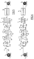
- the shearing means 5 are formed by a classic shear controlled by means 4 of detection and intended to cut the tail successively 1a of the first coil 1 and the head 2a of the second coil 2.
- the shearing means 5 can be formed by two ordered shears by means of detection, on the one hand, of the tail 1a of the first coil 1 and, on the other hand, of the head 2a of the second coil 2.
- a first shear is arranged in relation to the direction of travel of the strips metal, upstream of the positioning assembly 10 and holding edges to be welded and is intended for cut the head 2a of the second coil 2 and a second shears are arranged downstream of the assembly 10 of positioning and holding edges to be welded and is intended to cut the tail 1a of the first coil 1.
- the detection means 4 are constituted by example by at least one photocell.
- the first guide and support means 6a metal strips is formed by at least one series horizontal rollers each comprising two rollers lower 60a, 62a and an upper roller 61a between which circulate the metal bands.
- the upper roller 61a is disposed between the lower rollers, respectively 60a and 62a, and the three rollers 60a, 61a and 62a are movable simultaneously vertically by suitable means not represented.
- the second means 6b for guidance and support metal strip is also formed by at least a series of horizontal rollers each comprising two lower rollers 60b and 62b and an upper roller 61b.
- the upper roller 61b is disposed between the lower rollers 60b and 62b and the three rollers 60b, 61b and 62b are vertically movable.
- the rollers 60b, 61b and 62b can be moved horizontally in the opposite direction to the direction of travel of metal bands.
- the rollers 60b, 61b and 62b can be driven in direction opposite to the direction of travel of the bands metallic.
- the accumulator system 7 of the strip of the first reel 1 has a plurality of rollers 71 vertically movable and one plurality of fixed rollers 72.
- the tape enters the accumulator system by one end, alternately wraps around rollers 71 and 72 and spring of said accumulator system by the other end.
- the means 20 for positioning the tail 1a of the first coil 1 are formed by at least one lower shoe 21 extending parallel to the plane of joint of the weld edges of the tail 1a of the first coil 1 and head 2a of the second coil 2.
- This lower shoe 21 forms a surface of continuous contact with the underside of the tail 1a of the first coil 1 and is movably mounted on a support table 22, perpendicular to the joint plane said edges to be welded.
- This lower shoe 21 has two pins 23 protruding from its lower surface.
- Each pawn 23 enters a light 24 formed in the support table 22 so as to ensure the guiding the lower shoe 21 during its movement transverse to the joint plane of the edges at solder.
- the means 30 for positioning the edge to solder the tail 1a of the first coil 1 are formed by a longitudinal and retractable stop 31.
- the stop 31 is connected to a mechanism 32 for vertical displacement of said stop 31 and is arranged vertically so that the parting line passing through its lateral face located opposite the skate lower 20 is confused with the axis of the laser beam 11.
- the mechanism 32 for vertical displacement of the stop 31 can be constituted by an eccentric mechanism or by double-acting cylinders.
- the means 40 for holding the edge to be welded the tail 1a of the first coil 1 in the axis of the laser beam 11 are formed by at least one shoe upper 41 vertically movable and extending parallel to the joint plane of the edges to be welded.
- This upper shoe 41 forms a surface of continuous contact with the upper face of the tail 1a of the first coil 1 and is arranged opposite the shoe lower 20.
- the lower shoe 20 and / or the upper shoe 41 can be replaced by several pads juxtaposed forming substantially continuous surfaces contact with the tail 1a of the first coil 1.
- the means 50 for tightening the tail 1a of the first coil 1 are formed by at least one jack 51 intended to exert pressure on the upper shoe 41 vertical to clamp said tail 1a of the first coil 1 between this upper shoe 41 and the lower shoe 21.
- the jack 51 comprises a body 52 supported by a beam 53 extending parallel to the upper shoe 41 and a rod 54 vertically movable and integral of said upper shoe 41.
- the assembly formed by the upper shoe 41, the jack 51 and the beam 53 can be moved vertically to lift said upper shoe 41 and leave enough space between the upper shoe 41 and the lower shoe 21 for the passage of the strips of coils 1 and 2.
- the vertical displacement of this set is provided by appropriate bodies not shown, such as for example by a rack system or a jack.
- the means 80 for positioning the head 2a of the second coil 2 are formed by at least one fixed lower shoe 81, resting on a support table 82, and extending parallel to the joint plane of the edges to be welded.
- the lower shoe 81 forms a surface of continuous contact with the underside of the head 2a of the second coil 2.
- the lower shoe 81 is supported by its lateral face 81a opposite to that opposite the plane of joint of the edges to be welded, on at least one stop member 83 secured to the support table 82.
- the means 90 for holding the edge to be welded the head 2a of the second coil 2 against the edge at solder the tail 1a of the first coil 1 are formed by at least one upper shoe 91 extending in parallel at the joint plane of the edges to be welded.
- This upper shoe 91 forms a surface of continuous contact with the upper face of the head 2a of the second coil 2 and is arranged opposite the shoe lower 81.
- the lower shoe 81 and the upper shoe 91 can be replaced by several juxtaposed pads forming substantially continuous contact surfaces with the head 2a of the second coil 2.
- the means 100 for clamping the head 2a of the second coil 2 are formed by at least one cylinder 101 intended to exercise on the upper pad 91 a vertical pressure to tighten said head 2a of the second coil 2 between this upper shoe 91 and the shoe lower 81.
- the jack 101 has a body 102 supported by a beam 103 extending parallel to the shoe upper 91 and a rod 104 movable vertically and secured to said upper shoe 91.
- the assembly formed by the upper shoe 91, the jack 101 and the beam 103 can be moved vertically of sufficient height to lift the upper shoe 91 and make provision between this upper shoe 91 and the lower shoe 81 a space allowing the passage of the bands.
- the vertical displacement of this set is ensured for example by a rack mechanism or a cylinder or any other suitable mechanism.
- the upper shoe 91 is supported by its lateral face 91a opposite to that opposite the plane of joint of the edges to be welded, on at least one stop member 92 secured to the beam 103.
- the stop members 83 and 92 avoid the sliding of the lower shoe 81 and of the upper shoe 91, when lateral pressure is applied exerted on the weld edges of the tail 1a of the first coil 1 and head 2a of the second coil 2, as will be seen later.
- the means 110 and 120 for pressurizing side of the edges to be welded of the two coils 1 and 2 are formed, on the one hand, by at least a first cylinder 111 associated with the lower shoe 21 and, on the other hand, by at at least a second cylinder 121 associated with the upper shoe 41.
- the jack 111 has a movable rod 112 horizontally and connected to the lower shoe 21 by at least one pin 113 which crosses the support table 22.
- two jacks 111 are associated with the lower shoe 21.
- the jack 121 is supported by the beam 53 and has a horizontally displaceable rod 122 which acts on the upper shoe 41 via the body 52 and the rod 54 of the jack 51.
- two jacks 121 are associated with the upper shoe 41.
- Cylinders 111 and 121 are ordered in synchronization and are intended to exercise on, respectively the lower shoe 21 and the upper shoe 41, pressure determined and directed in one direction perpendicular to the joint plane of the edges to be welded.
- the installation according to the invention works as follows.
- the first coil is placed on the unwinding means 3 and the strip is unwound.
- This strip passes through means of projection 5 between the rollers 60a, 60b and 60c, in the set 10 for positioning and holding the edges to be welded, between the rollers 60b, 61b and 62b, in the accumulation system 7, in treatment station 8 and is finally wound up in the form of a coil 1 by the winding device 9.
- the operator has placed the guide means 6a and 6b in the high position and raised the upper pads 41 and 91, as shown in Figs. 1 and 2.
- the detection means 4 detect the tail the tape from this first reel 1 which causes stopping the scrolling of the portion of the strip located between the shearing means 5 and the accumulation system 7, the portion of the strip located downstream of this accumulation system 7 continuing to move normally using the length of the accumulated tape in said accumulation system.
- the detection means 4 control the 5 shearing means which has the effect of cutting the tail 2a of the first coil 2, as shown in the Fig. 5.
- the operator controls the descent of the means 6b for guiding and supporting the tail 1a of the first reel 1, as well as the displacement of these guide and support means in the direction opposite to the direction of travel of the tape the first coil 1 so that the weld edge of the tail 1a of this first coil 1 comes to apply on the stop 31 in order to position said edge to be welded in the axis of the laser beam 11.
- the guide means 6b and supporting the tail 1a of the first coil can be driven in reverse so that the edge to solder the tail 1a of this first coil 1 comes apply to stop 31.
- the operator also controls the descent of the assembly constituted by the upper shoe 41, the jack 51 and the beam 53 to clamp the tail 1a of the first coil 1 between lower shoe 21 and upper shoe 41 and maintain the weld edge of the tail 1a of said first coil 1 in the axis of the laser beam 11, as shown in FIG. 6.
- the detection means 4 detect the head 2a of the second coil 2 and control the stop of the strip of this second coil 2 and the shearing means 5 for cutting the head 2a of said second coil 2.
- the operator controls the descent of these means 6a from guide and support to bring the welding edge of the head 2a of the second coil 2 against the edge to be welded of the tail 1a of the first reel 1, after having retracted the stop 31, as shown in FIG. 7.
- the cylinders 51 and 101 are pressurized and act on the upper skids, respectively 41 and 91, so as to tighten, on the one hand, the tail 1a of the first coil 1 between the upper shoe 41 and the shoe lower 21 and, on the other hand, the head 2a of the second coil between upper shoe 91 and lower shoe 81 and keep the edges to be welded in line with the laser beam 11.
- the clamping pressure exerted by the pads upper 41 and 91 is adjustable and can be determined depending on the characteristics and / or the thickness of the metal bands constituting the coils 1 and 2.
- the operator controls the pressurization cylinders 111 and 121.
- the rod 112 of the jack 111 acts via of pin 113, on the lower shoe 21 which is moves perpendicular to the joint plane of the edges to be welded and the rod 112 of the cylinder 121 acts, via of the jack 51, on the upper shoe 41 which moves perpendicular to the joint plane of the edges welding.
- the lateral pressure exerted by the cylinders 111 and 121 is adjustable and can be determined by depending on the characteristics and / or the thickness of the metal strips so as to avoid buckling of this and an overlap at the joint plane.
- the operator controls the movement of the welding assembly so that the beam laser 11 moves above the joint plane and ensures welding the weld edges of the tail 1a of the first coil 1 with head 2a of the second coil 2.
- the strip portion of the first coil 1 located downstream of the accumulator system 7 takes place normally and the length of the strip in the accumulator decreases.
- the operator controls the rise, on the one hand, of beams 53 and 103 which has the effect of lifting the upper skids 41 and 91 and, on the other hand, means 6a and 6b for guiding and support metal strips so as to avoid these metal strips are in contact with the lower pads 21 and 81 during the scrolling of these bands.
- the installation according to the invention allows the joining and welding of two coils without disturbing the processing stations located downstream of this installation and to avoid breakage level of the junction between the two butted coils, by welding the edges with a laser beam.
- the installation according to the invention does not has only one single shear for cutting successively the tail of the first reel and the head of the second coil.
- This shear is arranged at outside of the positioning assembly and maintenance of the edges to be welded of the two coils.
- the installation according to the invention allows for a perfect quality weld while avoiding excess thickness in the welded area thus avoiding marking of the strip at the time of tape winding.
Landscapes
- Engineering & Computer Science (AREA)
- Physics & Mathematics (AREA)
- Optics & Photonics (AREA)
- Mechanical Engineering (AREA)
- Plasma & Fusion (AREA)
- Laser Beam Processing (AREA)
- Winding, Rewinding, Material Storage Devices (AREA)
- Manufacture Of Motors, Generators (AREA)
- Butt Welding And Welding Of Specific Article (AREA)
Claims (21)
- Anlage zum Aneinanderfügen und zum Schweißen von zwei aufgewickelten Metallbändern (1,2) mittels eines Laserstrahls (11), um ein kontinuierliches Metallband herzustellen, bestehend aus:Mitteln zum Abrollen (3) und Aufrollen (9) der Spulen (1,2),einer Stauvorrichtung (7) für das Band der ersten Spule (1),Mitteln (4) zum Abtasten des Endes (1a) der ersten Spule (1) und des Anfanges (2a) der zweiten Spule (2),Mitteln (5) zum Zerschneiden des Endes (1a) der ersten Spule (1) und des Anfanges (2a) der zweiten Spule (2),Mitteln (6a,6b) zum Führen und Tragen des metallischen Bandes der Spulen (1,2),einer Anordnung (10) zum Positionieren und Halten der Schweißränder des Endes (1a) der ersten Spule (1) und des Anfanges (2a) der zweiten Spule (2) derart, daß diese aneinander und in der Achse des Laserstrahls (11) liegen, bestehend aus Mitteln (20) zum Positionieren des Endes (1a) der ersten Spule (1) in bezug auf eine horizontale Referenzebene, Mitteln (40) zum Halten des Schweißrandes des Endes (1a) der ersten Spule (1) in der Achse des Laserstrahls (11), Mitteln (50) zum Festklemmen des Endes (1a) der ersten Spule (1), Mitteln (80) zum Positionieren des Anfanges (2a) der zweiten Spule (2) in bezug auf die horizontale Ebene, Mitteln (90) zum Halten des Schweißrandes des Anfanges (2a) der zweiten Spule (2) an dem Schweißrand des Endes (1a) der ersten Spule (1) und Mitteln (100) zum Festklemmen des Anfanges (2a) der zweiten Spule (2),und einer Vorrichtung zum Schweißen mittels eines Laserstrahls, die in bezug auf die Verbindungsebene, gebildet durch die Schweißränder der Spulen (1,2), verstellbar ist,
gekennzeichnet durch eine Vorrichtung (10) zum Positionieren und Halten der Schweißränder, bestehend außerdem aus Mitteln (30) zum Positionieren der Schweißränder des Endes (1a) der ersten Spule (1) in der Achse des Laserstrahls (11) und Mitteln (110,120) zum Ausüben eines seitlichen Druckes auf die Schweißränder der Bänder der beiden Spulen (1,2). - Anlage nach Anspruch 1, dadurch gekennzeichnet, daß die Mittel (5) zum Zerschneiden durch zwei Schneidwerkzeuge gebildet werden, die durch die Mittel (4) zum Abtasten gesteuert werden, daß das eine Schneidwerkzeug in bezug auf die Richtung des Abrollens des Metallbandes stromaufwärts von der Vorrichtung (10) zum Positionieren und Halten der Schweißränder angeordnet ist und bestimmt ist, den Anfang (2a) der zweiten Spule (2) zu beschneiden, und daß das zweite Schneidwerkzeug in bezug auf die Richtung des Abrollens des Metallbandes stromabwärts von der Vorrichtung (10) zum Positionieren und Halten der Schweißränder angeordnet ist und bestimmt ist, das Ende (1a) der ersten Spule (1) zu beschneiden.
- Anlage nach Anspruch 1, dadurch gekennzeichnet, daß die Mittel zum Führen und Tragen des metallischen Bandes durch mindestens zwei Reihen (6a,6b) aus horizontalen Rollen gebildet werden, die vertikal verstellbar sind und von denen jede zwei untere Rollen (60a,62a und 60b,62b) und eine obere Rolle (61a und 61b) aufweist, zwischen denen die metallischen Bänder laufen, wobei die obere Rolle (61a und 61b) jeder Reihe (6a und 6b) zwischen den unteren Rollen (60a,62a und 60b,62b) angeordnet ist.
- Anlage nach Anspruch 1 und 3, dadurch gekennzeichnet, daß mindestens eine erste Reihe (6a) von Rollen stromaufwärts von der Anordnung (10) zum Positionieren und Halten der Schweißränder in bezug auf das Ablaufen des Metallbandes angeordnet ist.
- Anlage nach Anspruch 1 und 3, dadurch gekennzeichnet, daß mindestens eine zweite Reihe (6b) von Rollen stromabwärts von der Anordnung (10) zum Positionieren und Halten der Schweißränder in bezug auf das Ablaufen des metallischen Bandes angeordnet ist.
- Anlage nach Anspruch 4 und 5, dadurch gekennzeichnet, daß die zweite Reihe (6b) der Rollen horizontal in entgegengesetzter Richtung zum Ablaufen des metallischen Bandes verstellbar ist.
- Anlage nach Anspruch 1, dadurch gekennzeichnet, daß die Mittel (20) zum Positionieren des Endes (1a) der ersten Spule (1) durch mindestens einen unteren Schuh (21) gebildet werden, der sich parallel zur Verbindungsebene der Schweißränder erstreckt, eine Kontaktfläche bildet, die mit der unteren Fläche des Endes (1a) der ersten Spule (1) zusammenfällt, und auf einem Tragtisch (22) senkrecht zur Verbindungsebene der Schweißränder verstellbar montiert ist.
- Anlage nach Anspruch 1 und 7, dadurch gekennzeichnet, daß die Mittel (30) zum Positionieren des Schweißrandes des Endes (1a) der ersten Spule (1) von einem länglichen und versenkbaren Anschlag (31) gebildet werden, der vertikal angeordnet ist, so daß die Ebene, die durch seine seitliche Fläche gegenüber dem unteren Schuh (21) gebildet wird, mit der Achse des Lasers (11) zusammenfällt.
- Anlage nach Ansoruch 1 und 7, dadurch gekennzeichnet, daß die Mittel (40) zum Halten des Schweißrandes des Endes (1a) der ersten Spule (1) in der Achse des Laserstrahls (11) durch mindestens einen oberen Schuh (41) gebildet werden, der vertikal verstellbar ist, sich parallel zur Verbindungsebene der Schweißränder erstreckt, der eine durchgehende Kontaktfläche mit der oberen Fläche des Endes (1a) der ersten Spule (1) bildet und dem unteren Schuh (21) gegenüberliegt.
- Anlage nach Anspruch 1, 7 und 9, dadurch gekennzeichnet, daß die Mittel (50) zum Festklemmen des Endes (1a) der ersten Spule (1) durch mindestens eine Schraubenwinde (51) gebildet werden, die auf den oberen Schuh (41) einen vertikalen Druck ausüben kann, um das Ende (1a) der ersten Spule (1) zwischen dem oberen Schuh (41) und dem unteren Schuh (21) einzuklemmen.
- Anlage nach Anspruch 9, dadurch gekennzeichnet, daß die Schraubenwinde (51) einen Körper (52), der von einem Träger (53) getragen wird, der sich parallel zu dem oberen Schuh (41) erstreckt, und eine Stange (54) aufweist, die vertikal vestellbar ist und mit dem oberen Schuh (41) fest verbunden ist.
- Anlage nach einem der Ansprüche 9 bis 11, dadurch gekennzeichnet, daß die Anordnung an dem oberen Schuh (41) der Schraubenwinde (51) und dem Träger (53) vertikal verstellbar ist.
- Anlage nach Anspruch 1, dadurch gekennzeichnet, daß die Mittel (80) zum Positionieren des Anfanges (1a) der zweiten Spule (2) durch mindestens einen unteren festen Schuh (81) gebildet werden, der sich auf einem Tragtisch (82) abstützt, sich parallel zu der Verbindungsebene der Schweißränder erstreckt und eine Kontaktfläche bildet, die mit der unteren Fläche des Anfanges (2a) der zweiten Spule (2) zusammenfällt.
- Anlage nach Anspruch 13, dadurch gekennzeichnet, daß sich der untere Schuh (81) mit seiner Seitenfläche (81a), die in bezug auf die Schweißverbindungsebene auf der anderen Seite liegt, an mindestens einem Anschlag (83) abstützen kann, der mit dem Tragtisch (89) fest verbunden ist.
- Anlage nach Anspruch 1 und 13, dadurch gekennzeichnet, daß die Mittel (90) zum Halten des Schweißrandes des Anfanges (2a) der zweiten Spule (2) gegen den Schweißrand des Endes (1a) der ersten Spule (1) durch mindestens einen oberen Schuh (91) gebildet werden, der sich parallel zur Verbindungsebene der Schweißränder erstreckt, eine Kontaktfläche bildet, die mit der oberen Fläche des Anfanges (2a) der zweiten Spule (2) zusammenfällt, und der gegenüber dem unteren Schuh (81) angeordnet ist.
- Anlage nach Anspruch 15, dadurch gekennzeichnet, daß die Mittel (100) zum Festklemmen des Anfanges (2a) der zweiten Spule (2) durch mindestens eine Schraubenwinde (101) gebildet werden, die auf den oberen Schuh (91) einen vertikalen Druck ausüben kann, um den Anfang (2a) der zweiten Spule (2) zwischen dem oberen Schuh (91) und dem unteren Schuh (81) einzuklemmen.
- Anlage nach Anspruch 16, dadurch gekennzeichnet, daß die Schraubenwinde (101) einen Körper (102), der von einem Träger (103) getragen wird, welcher sich parallel zum oberen Schuh (91) erstreckt, und eine Stange (104) aufweist, die vertikal verstellbar ist und fest mit dem oberen Schuh (91) verbunden ist.
- Anlage nach einem der Ansprüche 15 bis 17, dadurch gekennzeichnet, daß die Anordnung, gebildet durch den oberen Schuh (91), die Schraubenwinde und den Träger (103), vertikal verstellbar ist.
- Anlage nach Anspruch 15 und 16, dadurch gekennzeichnet, daß sich der obere Schuh (91) mit seiner Seitenwand (91a), die auf der der Verbindungsebene der Schweißränder abgewandten Seite angeordnet ist, an mindestens einem Anschlag (92) abstützen kann, der mit dem Träger (103) fest verbunden ist.
- Anlage nach Anspruch 1, dadurch gekennzeichnet, daß die Mittel (110,120), mit denen ein seitlicher Druck auf die Schweißränder der beiden Spulen (1,2) ausgeübt werden kann, einerseits aus mindestens einer ersten Schraubenwinde (111), die mit dem unteren Schuh (21) zum Positionieren des Endes (1a) der ersten Spule (1) verbunden ist, und andererseits aus mindestens einer zweiten Schraubenwinde (121), die mit dem oberen Schuh (41) zum Halten des Endes (1a) der ersten Spule (1) verbunden ist, besteht, daß die Schraubenwinden (111,121) auf den unteren Schuh (21) und den oberen Schuh (41) einen Druck ausüben können, der senkrecht zur Verbindungsebene der Schweißränder ist.
- Anlage nach Anspruch 20, dadurch gekennzeichnet, daß die Schraubenwinden (111,121) synchron gesteuert werden.
Applications Claiming Priority (2)
| Application Number | Priority Date | Filing Date | Title |
|---|---|---|---|
| FR9315384A FR2713963B1 (fr) | 1993-12-21 | 1993-12-21 | Installation de raboutage et de soudage au moyen d'un faisceau laser de deux bobines de bandes métalliques pour former une bande métallique continue. |
| FR9315384 | 1993-12-21 |
Publications (2)
| Publication Number | Publication Date |
|---|---|
| EP0659518A1 EP0659518A1 (de) | 1995-06-28 |
| EP0659518B1 true EP0659518B1 (de) | 1998-04-22 |
Family
ID=9454172
Family Applications (1)
| Application Number | Title | Priority Date | Filing Date |
|---|---|---|---|
| EP94402816A Revoked EP0659518B1 (de) | 1993-12-21 | 1994-12-07 | Anlage zum Aneinanderfügen und zum Schweissen von zwei aufgewickelten Metallbänder mittels eines Laserstrahls um ein kontinuierliches Metallband herzustellen |
Country Status (7)
| Country | Link |
|---|---|
| EP (1) | EP0659518B1 (de) |
| JP (1) | JPH0839276A (de) |
| KR (1) | KR950017056A (de) |
| AT (1) | ATE165264T1 (de) |
| DE (1) | DE69409772T2 (de) |
| ES (1) | ES2115902T3 (de) |
| FR (1) | FR2713963B1 (de) |
Families Citing this family (20)
| Publication number | Priority date | Publication date | Assignee | Title |
|---|---|---|---|---|
| GB2332164A (en) * | 1997-12-13 | 1999-06-16 | Harrison Saw & Tool Ltd | Continuous band manufacture |
| DE102006028102A1 (de) * | 2006-06-19 | 2007-12-20 | Siemens Ag | Abhaspeleinrichtung |
| EP1870194A1 (de) * | 2006-06-21 | 2007-12-26 | Corus Technology BV | Verfahren zur Herstellung eines kontinuierlichen metallischen Bleches durch Laser-Stumpfschweissen , mit einem eine multimodale Leistungsverteilung aufweisenden Laser |
| EP2049300B1 (de) * | 2006-08-04 | 2010-01-06 | Rasselstein GmbH | Verfahren zur herstellung eines korrosionsbeständigen und umformbaren blechs mit vollflächigem beschichten der gefügten thermisch behandelten stahlbleche |
| DE102006050287B4 (de) | 2006-10-23 | 2021-10-28 | Fecker Gmbh Maschinenbau | Bandanlage zum Geraderichten von zu Coils aufgewickeltem Bandmaterial und zur Einführung desselben in eine Weiterverarbeitungsmaschine |
| KR100915998B1 (ko) * | 2008-10-31 | 2009-09-10 | 주식회사 송은금속 | 코일 연결용 용접장치 및 이 장치를 통하여 제조된 코일 |
| DE102008060467B4 (de) * | 2008-12-05 | 2013-08-01 | Thyssenkrupp Tailored Blanks Gmbh | Verfahren zur Herstellung von maßgeschneiderten Blechbändern |
| CN102556724A (zh) * | 2011-12-08 | 2012-07-11 | 宁波泰甬汽车零部件有限公司 | 保持带料加工生产线不间断供料的方法 |
| CN103143587B (zh) * | 2013-03-18 | 2015-09-16 | 济钢集团国际工程技术有限公司 | 适用于双机架冷轧机的焊接引带提高成材率的装置及方法 |
| KR101448399B1 (ko) * | 2013-08-06 | 2014-10-07 | 김제환 | 메탈라스 커팅장치 |
| JP6511664B2 (ja) * | 2016-02-17 | 2019-05-15 | 株式会社ナ・デックスプロダクツ | レーザ溶接方法 |
| CN106891123B (zh) * | 2017-03-22 | 2019-08-30 | 无锡先导智能装备股份有限公司 | 焊带定位装置及定位方法 |
| CN107570867A (zh) * | 2017-07-25 | 2018-01-12 | 东莞盛翔精密金属有限公司 | 一种连线自动化焊接机 |
| WO2020150710A1 (en) * | 2019-01-20 | 2020-07-23 | Techreo Llc | Methods for making layered tubular structures |
| CN110434457A (zh) * | 2019-07-19 | 2019-11-12 | 中车青岛四方机车车辆股份有限公司 | 激光双面焊接装置及其激光双面焊接方法 |
| CN110732760A (zh) * | 2019-11-18 | 2020-01-31 | 中国航发贵州黎阳航空动力有限公司 | 一种板材零件定位焊夹具 |
| EP4371679B1 (de) * | 2022-11-15 | 2026-04-15 | Universität Kassel | Verlängern von bandförmigen werkstoffen |
| KR20250029440A (ko) * | 2023-08-23 | 2025-03-05 | 삼성전자주식회사 | 와이어 공급 모듈 및 이를 포함하는 와이어 본딩 장치 |
| GB2637722A (en) * | 2024-01-31 | 2025-08-06 | Tbs Eng Ltd | Method and system for joining strips of battery grid |
| CN117862697B (zh) * | 2024-02-27 | 2024-07-26 | 苏州天弘激光股份有限公司 | 一种料带首尾自动激光切焊一体机及其加工工艺 |
Family Cites Families (4)
| Publication number | Priority date | Publication date | Assignee | Title |
|---|---|---|---|---|
| DE151848T1 (de) * | 1984-02-27 | 1985-12-05 | Kawasaki Steel Corp., Kobe, Hyogo | Vorrichtung zum stumpfschweissen von stahlbaendern mit einem laserstrahl in einer stahlbandverarbeitungsstrasse. |
| US4854493A (en) * | 1986-02-28 | 1989-08-08 | Kawasaki Steel Corporation | Method and apparatus for cutting welding steel strips |
| EP0438609B1 (de) * | 1990-01-20 | 1993-09-01 | Thyssen Industrie Ag Maschinenbau | Verfahren und Einrichtung zum Aneinanderschweissen von Stahlblechen mittels Laserstrahlschweissverfahren |
| DE4100302C1 (de) * | 1991-01-08 | 1992-02-06 | Bwg Bergwerk- Und Walzwerk-Maschinenbau Gmbh, 4100 Duisburg, De |
-
1993
- 1993-12-21 FR FR9315384A patent/FR2713963B1/fr not_active Expired - Fee Related
-
1994
- 1994-12-07 DE DE69409772T patent/DE69409772T2/de not_active Revoked
- 1994-12-07 ES ES94402816T patent/ES2115902T3/es not_active Expired - Lifetime
- 1994-12-07 EP EP94402816A patent/EP0659518B1/de not_active Revoked
- 1994-12-07 AT AT94402816T patent/ATE165264T1/de not_active IP Right Cessation
- 1994-12-19 KR KR1019940035010A patent/KR950017056A/ko not_active Withdrawn
- 1994-12-21 JP JP6335678A patent/JPH0839276A/ja not_active Withdrawn
Also Published As
| Publication number | Publication date |
|---|---|
| DE69409772T2 (de) | 1998-10-22 |
| ES2115902T3 (es) | 1998-07-01 |
| DE69409772D1 (de) | 1998-05-28 |
| JPH0839276A (ja) | 1996-02-13 |
| FR2713963B1 (fr) | 1996-03-08 |
| FR2713963A1 (fr) | 1995-06-23 |
| EP0659518A1 (de) | 1995-06-28 |
| KR950017056A (ko) | 1995-07-20 |
| ATE165264T1 (de) | 1998-05-15 |
Similar Documents
| Publication | Publication Date | Title |
|---|---|---|
| FR2713963A1 (fr) | Installation de raboutage et de soudage au moyen d'un faisceau laser de deux bobines de bandes métalliques pour former une bande métallique continue. | |
| CA2139621C (fr) | Dispositif de mise en reference bord a bord d'au moins deux flans de tole dans une installation de soudage par faisceau a haute densite d'energie | |
| EP0622152B1 (de) | Bearbeitungsstation mit Stümpfpositionierung und Laserstrahlschweissen von zwei Blechkanten | |
| EP0845309B1 (de) | Automatische Maschine zum transversal Verbinden von Metallbändern | |
| EP2064023A1 (de) | Vorrichtung zur schweissverbindung von bahnenmetallstreifen | |
| EP0583999B1 (de) | Vorrichtung zum kontinuierlichen Rand-an-Rand-Ausrichten und Schweissen von mit einer Laserstrahlung mindestens zwei Blechzuschnitten | |
| CH444631A (fr) | Procédé pour joindre les extrémités de deux feuillards et installation pour sa mise en oeuvre | |
| EP2821176A1 (de) | Vorrichtung zum Verschieben einer Anordnung zum Schneiden und Schweißen von Metallbändern ; Verfahren zum Schneiden und Schweissen unter Verwendung solcher Vorrichtung | |
| EP1127654B1 (de) | Verfahren und Vorrichtung zum Stumpfschweissen von metallischen Blechen | |
| EP1591190B1 (de) | Verfahren zum Verschweissen zweier Metallbleche | |
| US4850522A (en) | Steel strip splicing station | |
| FR2685236A1 (fr) | Dispositif de guidage et de transfert d'au moins deux flans de tole a souder. | |
| EP0600757B1 (de) | Positioniervorrichtung für Blechtafeln in einer Schweisseinrichtung zum kontinuierlichen Stumpfschweissen dieser Blechtafeln | |
| US8305588B2 (en) | Position-measuring method and device adapted for the positioning of a wheel | |
| EP0650796B1 (de) | Verfahren und Vorrichtung zum Herstellen der Rechtwinkligkeit und zum Verschweissen metallischer Bänder | |
| FR2529814A1 (fr) | Installation de soudage de bandes pour relier des toles des plaques ou des bandes | |
| FR2625136A1 (fr) | Procede et installation de fabrication de plaques composites | |
| FR2654956A1 (fr) | Enrouleuse a bandes. | |
| FR2703274A1 (fr) | Procédé et installation de soudage de bandes métalliques. | |
| FR2706793A1 (en) | Process and device for joining cold-rolled steel sheets | |
| JP3397922B2 (ja) | 移動鋼板の接合方法および装置 | |
| FR2491789A1 (fr) | Dispositif d'alimentation de barres d'armature en acier pour beton | |
| EP0781621B1 (de) | Verfahren zum Spleissen von metallischen Bändern und Maschine zur Durchführung des Verfahrens | |
| FR2495995A1 (fr) | Machine automatique pour le frettage de pieces de bois et pieces de bois obtenues | |
| JPH07241620A (ja) | 鋼板ストリップコイルのプリパレ−ション装置 |
Legal Events
| Date | Code | Title | Description |
|---|---|---|---|
| PUAI | Public reference made under article 153(3) epc to a published international application that has entered the european phase |
Free format text: ORIGINAL CODE: 0009012 |
|
| AK | Designated contracting states |
Kind code of ref document: A1 Designated state(s): AT BE CH DE DK ES FR GB GR IT LI LU NL PT SE |
|
| 17P | Request for examination filed |
Effective date: 19950828 |
|
| 17Q | First examination report despatched |
Effective date: 19960708 |
|
| GRAG | Despatch of communication of intention to grant |
Free format text: ORIGINAL CODE: EPIDOS AGRA |
|
| GRAG | Despatch of communication of intention to grant |
Free format text: ORIGINAL CODE: EPIDOS AGRA |
|
| GRAH | Despatch of communication of intention to grant a patent |
Free format text: ORIGINAL CODE: EPIDOS IGRA |
|
| GRAH | Despatch of communication of intention to grant a patent |
Free format text: ORIGINAL CODE: EPIDOS IGRA |
|
| GRAA | (expected) grant |
Free format text: ORIGINAL CODE: 0009210 |
|
| AK | Designated contracting states |
Kind code of ref document: B1 Designated state(s): AT BE CH DE DK ES FR GB GR IT LI LU NL PT SE |
|
| REF | Corresponds to: |
Ref document number: 165264 Country of ref document: AT Date of ref document: 19980515 Kind code of ref document: T |
|
| REG | Reference to a national code |
Ref country code: CH Ref legal event code: EP |
|
| ITF | It: translation for a ep patent filed | ||
| REF | Corresponds to: |
Ref document number: 69409772 Country of ref document: DE Date of ref document: 19980528 |
|
| GBT | Gb: translation of ep patent filed (gb section 77(6)(a)/1977) |
Effective date: 19980515 |
|
| REG | Reference to a national code |
Ref country code: ES Ref legal event code: FG2A Ref document number: 2115902 Country of ref document: ES Kind code of ref document: T3 |
|
| PG25 | Lapsed in a contracting state [announced via postgrant information from national office to epo] |
Ref country code: DK Free format text: LAPSE BECAUSE OF FAILURE TO SUBMIT A TRANSLATION OF THE DESCRIPTION OR TO PAY THE FEE WITHIN THE PRESCRIBED TIME-LIMIT Effective date: 19980722 |
|
| PG25 | Lapsed in a contracting state [announced via postgrant information from national office to epo] |
Ref country code: GR Free format text: LAPSE BECAUSE OF FAILURE TO SUBMIT A TRANSLATION OF THE DESCRIPTION OR TO PAY THE FEE WITHIN THE PRESCRIBED TIME-LIMIT Effective date: 19980724 |
|
| REG | Reference to a national code |
Ref country code: PT Ref legal event code: SC4A Free format text: AVAILABILITY OF NATIONAL TRANSLATION Effective date: 19980618 |
|
| PG25 | Lapsed in a contracting state [announced via postgrant information from national office to epo] |
Ref country code: LI Free format text: LAPSE BECAUSE OF NON-PAYMENT OF DUE FEES Effective date: 19981231 Ref country code: CH Free format text: LAPSE BECAUSE OF NON-PAYMENT OF DUE FEES Effective date: 19981231 |
|
| PLBI | Opposition filed |
Free format text: ORIGINAL CODE: 0009260 |
|
| PLBF | Reply of patent proprietor to notice(s) of opposition |
Free format text: ORIGINAL CODE: EPIDOS OBSO |
|
| 26 | Opposition filed |
Opponent name: HOOGOVENS STAAL BV, IJMUIDEN C/O HOOGOVENS CORPOR Effective date: 19990122 |
|
| NLR1 | Nl: opposition has been filed with the epo |
Opponent name: HOOGOVENS STAAL BV, IJMUIDEN C/O HOOGOVENS CORPORA |
|
| PLBF | Reply of patent proprietor to notice(s) of opposition |
Free format text: ORIGINAL CODE: EPIDOS OBSO |
|
| REG | Reference to a national code |
Ref country code: CH Ref legal event code: PL |
|
| PGFP | Annual fee paid to national office [announced via postgrant information from national office to epo] |
Ref country code: SE Payment date: 19991119 Year of fee payment: 6 Ref country code: AT Payment date: 19991119 Year of fee payment: 6 |
|
| PGFP | Annual fee paid to national office [announced via postgrant information from national office to epo] |
Ref country code: NL Payment date: 19991122 Year of fee payment: 6 |
|
| PGFP | Annual fee paid to national office [announced via postgrant information from national office to epo] |
Ref country code: PT Payment date: 19991124 Year of fee payment: 6 |
|
| PGFP | Annual fee paid to national office [announced via postgrant information from national office to epo] |
Ref country code: GB Payment date: 19991130 Year of fee payment: 6 |
|
| PGFP | Annual fee paid to national office [announced via postgrant information from national office to epo] |
Ref country code: FR Payment date: 19991201 Year of fee payment: 6 |
|
| PGFP | Annual fee paid to national office [announced via postgrant information from national office to epo] |
Ref country code: DE Payment date: 19991202 Year of fee payment: 6 |
|
| PGFP | Annual fee paid to national office [announced via postgrant information from national office to epo] |
Ref country code: ES Payment date: 19991209 Year of fee payment: 6 |
|
| PGFP | Annual fee paid to national office [announced via postgrant information from national office to epo] |
Ref country code: LU Payment date: 19991217 Year of fee payment: 6 |
|
| PGFP | Annual fee paid to national office [announced via postgrant information from national office to epo] |
Ref country code: BE Payment date: 20000106 Year of fee payment: 6 |
|
| PLBQ | Unpublished change to opponent data |
Free format text: ORIGINAL CODE: EPIDOS OPPO |
|
| PLAB | Opposition data, opponent's data or that of the opponent's representative modified |
Free format text: ORIGINAL CODE: 0009299OPPO |
|
| R26 | Opposition filed (corrected) |
Opponent name: HOOGOVENS STAAL BV, IJMUIDEN C/O HOOGOVENS CORPORA Effective date: 19990122 |
|
| RDAH | Patent revoked |
Free format text: ORIGINAL CODE: EPIDOS REVO |
|
| NLR1 | Nl: opposition has been filed with the epo |
Opponent name: HOOGOVENS STAAL BV, IJMUIDEN C/O HOOGOVENS CORPORA |
|
| RDAG | Patent revoked |
Free format text: ORIGINAL CODE: 0009271 |
|
| STAA | Information on the status of an ep patent application or granted ep patent |
Free format text: STATUS: PATENT REVOKED |
|
| 27W | Patent revoked |
Effective date: 20000720 |
|
| GBPR | Gb: patent revoked under art. 102 of the ep convention designating the uk as contracting state |
Free format text: 20000720 |
|
| REG | Reference to a national code |
Ref country code: PT Ref legal event code: MF4A Effective date: 20001110 |
|
| NLR2 | Nl: decision of opposition | ||
| PLAB | Opposition data, opponent's data or that of the opponent's representative modified |
Free format text: ORIGINAL CODE: 0009299OPPO |