EP0659527A1 - Verfahren und Vorrichtung zur Herstellung von Fliesen mit konstanter Dichte und gleichbleibender Dicke und so hergestellte Fliesen - Google Patents
Verfahren und Vorrichtung zur Herstellung von Fliesen mit konstanter Dichte und gleichbleibender Dicke und so hergestellte Fliesen Download PDFInfo
- Publication number
- EP0659527A1 EP0659527A1 EP94203545A EP94203545A EP0659527A1 EP 0659527 A1 EP0659527 A1 EP 0659527A1 EP 94203545 A EP94203545 A EP 94203545A EP 94203545 A EP94203545 A EP 94203545A EP 0659527 A1 EP0659527 A1 EP 0659527A1
- Authority
- EP
- European Patent Office
- Prior art keywords
- carriage
- plant
- tile
- feet
- mould
- Prior art date
- Legal status (The legal status is an assumption and is not a legal conclusion. Google has not performed a legal analysis and makes no representation as to the accuracy of the status listed.)
- Granted
Links
- 238000000034 method Methods 0.000 title claims abstract description 24
- 238000005056 compaction Methods 0.000 title claims description 17
- 239000000463 material Substances 0.000 claims abstract description 33
- 239000012528 membrane Substances 0.000 claims abstract description 22
- 239000000919 ceramic Substances 0.000 claims abstract description 13
- 238000009826 distribution Methods 0.000 claims abstract description 12
- 238000003825 pressing Methods 0.000 claims abstract description 11
- 238000004519 manufacturing process Methods 0.000 claims abstract description 8
- 238000012545 processing Methods 0.000 claims abstract description 5
- 238000005259 measurement Methods 0.000 claims description 5
- 239000010720 hydraulic oil Substances 0.000 claims description 4
- 229910000831 Steel Inorganic materials 0.000 claims description 2
- 230000008569 process Effects 0.000 claims description 2
- 230000001105 regulatory effect Effects 0.000 claims description 2
- 239000010959 steel Substances 0.000 claims description 2
- 238000009825 accumulation Methods 0.000 claims 1
- 238000004891 communication Methods 0.000 claims 1
- 230000001276 controlling effect Effects 0.000 claims 1
- 230000003111 delayed effect Effects 0.000 claims 1
- 230000010355 oscillation Effects 0.000 claims 1
- 239000003921 oil Substances 0.000 description 13
- 239000002184 metal Substances 0.000 description 7
- 230000007547 defect Effects 0.000 description 6
- 239000004927 clay Substances 0.000 description 5
- 238000012544 monitoring process Methods 0.000 description 5
- 229920001971 elastomer Polymers 0.000 description 4
- 238000010304 firing Methods 0.000 description 3
- 230000001788 irregular Effects 0.000 description 3
- 238000004804 winding Methods 0.000 description 3
- 238000006243 chemical reaction Methods 0.000 description 2
- 230000000994 depressogenic effect Effects 0.000 description 2
- 239000000806 elastomer Substances 0.000 description 2
- 239000007788 liquid Substances 0.000 description 2
- 230000000007 visual effect Effects 0.000 description 2
- 239000004636 vulcanized rubber Substances 0.000 description 2
- 238000010521 absorption reaction Methods 0.000 description 1
- 238000004873 anchoring Methods 0.000 description 1
- 230000015572 biosynthetic process Effects 0.000 description 1
- 239000002801 charged material Substances 0.000 description 1
- 239000000470 constituent Substances 0.000 description 1
- 230000008878 coupling Effects 0.000 description 1
- 238000010168 coupling process Methods 0.000 description 1
- 238000005859 coupling reaction Methods 0.000 description 1
- 239000010438 granite Substances 0.000 description 1
- 230000003993 interaction Effects 0.000 description 1
- 239000004973 liquid crystal related substance Substances 0.000 description 1
- 238000012986 modification Methods 0.000 description 1
- 230000004048 modification Effects 0.000 description 1
- -1 moisture content Substances 0.000 description 1
- 238000000465 moulding Methods 0.000 description 1
- 239000002245 particle Substances 0.000 description 1
- 230000002093 peripheral effect Effects 0.000 description 1
- 230000004044 response Effects 0.000 description 1
- 239000007779 soft material Substances 0.000 description 1
- 238000012360 testing method Methods 0.000 description 1
Images



Classifications
-
- B—PERFORMING OPERATIONS; TRANSPORTING
- B30—PRESSES
- B30B—PRESSES IN GENERAL
- B30B11/00—Presses specially adapted for forming shaped articles from material in particulate or plastic state, e.g. briquetting presses, tabletting presses
- B30B11/005—Control arrangements
-
- B—PERFORMING OPERATIONS; TRANSPORTING
- B28—WORKING CEMENT, CLAY, OR STONE
- B28B—SHAPING CLAY OR OTHER CERAMIC COMPOSITIONS; SHAPING SLAG; SHAPING MIXTURES CONTAINING CEMENTITIOUS MATERIAL, e.g. PLASTER
- B28B13/00—Feeding the unshaped material to moulds or apparatus for producing shaped articles; Discharging shaped articles from such moulds or apparatus
- B28B13/02—Feeding the unshaped material to moulds or apparatus for producing shaped articles
- B28B13/0215—Feeding the moulding material in measured quantities from a container or silo
- B28B13/023—Feeding the moulding material in measured quantities from a container or silo by using a feed box transferring the moulding material from a hopper to the moulding cavities
-
- B—PERFORMING OPERATIONS; TRANSPORTING
- B28—WORKING CEMENT, CLAY, OR STONE
- B28B—SHAPING CLAY OR OTHER CERAMIC COMPOSITIONS; SHAPING SLAG; SHAPING MIXTURES CONTAINING CEMENTITIOUS MATERIAL, e.g. PLASTER
- B28B17/00—Details of, or accessories for, apparatus for shaping the material; Auxiliary measures taken in connection with such shaping
- B28B17/0063—Control arrangements
- B28B17/0072—Product control or inspection
-
- B—PERFORMING OPERATIONS; TRANSPORTING
- B28—WORKING CEMENT, CLAY, OR STONE
- B28B—SHAPING CLAY OR OTHER CERAMIC COMPOSITIONS; SHAPING SLAG; SHAPING MIXTURES CONTAINING CEMENTITIOUS MATERIAL, e.g. PLASTER
- B28B3/00—Producing shaped articles from the material by using presses; Presses specially adapted therefor
- B28B3/003—Pressing by means acting upon the material via flexible mould wall parts, e.g. by means of inflatable cores, isostatic presses
Definitions
- This invention relates generally to a method for manufacturing ceramic tiles, and more specifically to a method for forming tiles of uniform compaction and thickness.
- the invention also relates to the means for implementing said method.
- Ceramic tiles in general are known to be formed in convenient moulds positioned on suitable forming presses.
- said presses are hydraulic and basically comprise:
- the operating pressure of said cylinder-piston unit can be adjusted as required, ie on the basis of the parameters for the work underway.
- the moulds to be associated with said presses comprise the three said plates, of which the intermediate plate comprises at least one forming cavity to be charged with at least one material to be compacted, the lower plate comprises at least one die to define the base of said at least one cavity and to form one of the two tile faces, and the upper plate is provided with at least one die to form the other tile face.
- said at least one material is charged by a carriage arranged to occupy a first position to the side of the die plate, where it receives said at least one material, and a second position overlying the die plate, where it discharges said at least one material into said at least one cavity.
- the to-and-fro movement of the carriage is generated by a connecting rod-crank system operated by a convenient drive unit, the carriage consisting of a rectangular frame with flaps fixed to two opposing sides thereof. Normally said flaps are fixed to those two sides of the frame which are parallel to the carriage movement.
- a feed hopper for said material is also associated with said carriage.
- the hopper is stationary and the respective carriage comprises a rear horizontal plate arranged to close and open the discharge mouth of the hopper when the carriage is in its advanced or discharge position and, respectively, when the carriage is in its withdrawn or loading position.
- the hopper is arranged to move relative to the carriage with reciprocating rectilinear motion parallel to the carriage movement.
- the depth of the forming cavity in the die plate is determined by the lower die which can assume three operating positions, namely:
- reverse face dies can have their active face formed in various ways.
- said active face can be defined:
- those dies provided for forming the tile exposed face and commonly known as “exposed face dies", have their active face defined by the surface of a metal structure.
- the invention relates to moulds provided with such isostatic dies.
- uniform compaction is achieved at the expense of geometrical or shape defects, in terms of a tile thickness which is not uniform from one point to another.
- said dies covered with a membrane closing at least one rear chamber filled with oil have numerous advantages, they have proved unsatisfactory in manufacturing relatively large dimension tiles of relatively small overall thicknesses.
- the degree of clay compact ion at the feet depends only on the reaction offered by the membrane consequent on its deformation, and it is apparent that where the membrane is thinnest, ie at the depressions in which the tile feet are formed, for equal absolute deformation it undergoes relative specific deformations which are much greater than those in surrounding regions where it is of greater thickness.
- the tile has a rather irregular surface, ie different thicknesses, at the depressions between said feet.
- the charging of the forming cavity is adjusted as a result of visual checks on the surface of the regions between the feet and on the uniformity or non-uniformity of the tile thickness.
- the main object of the present invention is to provide a method and its means of implementation able to produce tiles which are of uniform compaction and thickness and are statistically identical.
- the method of the invention comprises continuously forming tiles, automatically monitoring the planarity of those tile regions between the feet and, if unsatisfactory, to automatically modify at least one of the parameters governing the charging of the forming cavities, in accordance with an established priority based on the type, size and position of the defect shown up by said planarity monitoring.
- planarity monitoring and the possible adjustment of said at least one parameter are effected at a frequency equal to the production rate of the press, ie in practice in real time.
- planarity monitoring assumes a reference point or plane and measures the maximum distance between said reference and the tile region adjacent to the foot, to deduce from said measurement any geometrical irregularity on the rear of the tile, or in other words its non-uniformity of thickness.
- the various parameters responsible for the filling of the mould cavity are automatically adjusted on the basis of said non-uniformity.
- Adjustments are made only when the thickness non-uniformity exceeds a certain value considered acceptable, such as 0.2-0.3 mm.
- the filling irregularities occur in the direction of movement of the charging carriage, hence the thickness non-uniformity measurements are made in the same direction, this being the direction in which the tile advances after being formed.
- the means for implementing said method comprise an isostatic mould to be positioned on a hydraulic press, those dies thereof for forming the tile laying face comprising an elastomeric membrane carrying impressions for forming the tile feet, and closing a series of rear chambers for containing hydraulic oil, said chambers being hydraulically connected to the press cylinder-piston unit which exerts the forming pressure.
- said hydraulic connection is made by a hydraulic circuit which incorporates, starting from said cylinder-piston unit, a valve unit arranged to allow oil to pass alternately in the two opposing directions, and at least one pressure multiplier device, during the course of each pressing the opening of said valve unit in one direction depending on a pressure less than the maximum operating pressure of said cylinder-piston unit, whereas the opening of said valve unit in the opposite direction depends on the repositioning of said pressure multiplier device.
- a hydraulic counterpressure is made available such as to raise the slab during the final pressing stage.
- a device able to measure the surface conformation or planarity of said depressed regions, and which is combined with a system which on the basis of the data obtained by said measuring device acts on the means on which the charging of the forming cavity depends.
- said system consists of an electronic device the input of which is connected to said measuring device, and the output of which is connected to said means on which said charging depends, so as to adjust, or not, its manner of operation and possibly its configuration in response to the readings taken.
- the forming cavity is filled with a layer having practically uniform density and thickness, so that besides being uniformly compacted the tiles also have uniform thickness.
- Figure 1 shows in combination the hydraulic cylinder-piston unit 1 of a ceramic press, a reverse face die 2 pertaining to a ceramic mould for locating on the bed of said press, and a hydraulic circuit 3 connecting together said unit 1 and die 2 as described hereinafter, and into which there are connected a valve unit 4 and a pressure multiplier 5.
- said cylinder-piston unit 1 comprises a cylinder 10 which is connected to a source of pressurized hydraulic liquid, and within which a piston 11 is mounted to slide under sealed conditions.
- the rod 12 of this latter emerges from the lower end of the cylinder 10 where it fixedly carries the press movable cross-member which supports the mould upper plate (not shown), provided lowerly with a die, also not shown.
- Said (upper) die cooperates with the (lower) die 2 to form the tiles, by moulding their exposed face.
- the mutual position of the two dies can be inverted.
- the reference numeral 45 indicates the ceramic mould intermediate plate or die plate, which can either be fixed to the press bed or be supported on said bed by yieldable supports, not shown, of hydraulic or mechanical type.
- Said die plate 45 comprises at least one forming cavity 46 for charging at least one pulverulent material 78 to be compacted, such as atomized clay.
- the base of the cavity 46 is defined by the die 2, which can move in height as explained in the introduction.
- the die 2 is fixed to the mould lower plate 44, which is supported by the press bed by way of a series of actuators 440, for example four in number.
- said actuators 440 are of fine adjustment type, for the reasons given hereinafter.
- actuators 440 are remotely adjustable.
- the carriage 47 is driven to slide forwards (towards the right in Figure 1) and rearwards (towards the left) by a connecting rod-crank system 49 operated by a drive unit 48.
- said unit 48 comprises a direct current electric motor with an electronic card for continuous r.p.m. adjustment.
- a clay feed hopper 14, of known type in the illustrated embodiment, is associated with the carriage 47.
- the carriage 47 comprises a rectangular frame 64, the front cross-member of which is provided with a pusher 65 and a scraper 66.
- the purpose of the pusher 65 is to remove the tiles 99 ( Figure 1) from the die plate 45 and rest them on a conveyor 100 during the outward travel of the carriage, whereas the scraper 66 levels the clay layer 78 deposited in the cavity 46 and cleans the upper face of the die plate 45 during the return travel of the carriage 47.
- Each flap 16 is provided with a series of equidistant plates 17 arranged perpendicular thereto and symmetrically about it, the plates of each series being interposed between the plates of the two adjacent series.
- Each flap 16 comprises two opposing through holes 160 through which there are inserted, with a certain radial clearance, two threaded shafts 67 the threads of which upperly engage two elastic rods 68.
- Said threaded shafts 67 are rotated by two electric motors 670 of double direction of rotation.
- Said shafts 67 have a thread which for one half of their length is left handed and for the other half is right handed.
- Said rods 68 are elastically flexible, and consist for example of pieces of harmonic steel wire.
- Each rod 68 supports the corresponding end of the flap 16 by way of a pin 69 which is perpendicular to this latter ( Figures 6 and 7).
- the pin 69 has a frusto-conical end which together with a terminal frusto-conical head 70 forms a circumferential groove of V-shaped cross-section.
- This groove engages a respective hole in the flap 16, this hole having flared ends the generating lines of which define an angle less than the angle at the vertex of said V shape.
- Said adjustment is made by a threaded push rod 71 controlled by a micromotor 171 of two directions of rotation, which is fixed below the pin 69.
- the push rod 71 rests against the rear face (with reference to the direction of advancement of the carriage 47) of the flap, against the opposite face of which there acts a flat spring 72.
- the purpose of the rods 68 is to discretely adjust the distance between the flaps 16, in particular at the commencement of the production cycle of a determined material;
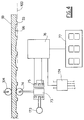
- It comprises a series of identical units (for example four in number) positioned side by side in a direction transverse to the conveyor 100 and all connected to a central processing and control system 174, such as a programmable electronic processor.
- a central processing and control system 174 such as a programmable electronic processor.
- Each individual unit comprises a vertical core 73 slidable within a hollow body 75 provided with three windings, of which the central winding is connected to a power supply 173.
- the core 73 supports an idle roller 74 with its axis horizontal and positioned transverse to the conveyor 100 to make contact with the laying face of the tiles 99.
- Said other two windings are connected in series and their ends are connected to a reading unit 76 connected to the central processor 174 and to a display 77, for example of liquid crystal type.
- the number of display cells of this latter is at least equal to the number of depressed regions 66 of the tile 99 to be contacted by the roller 74.
- the central control processor 174 is connected at its input to the units 76, and at its output (dashed lines at the bottom of Figure 4) to the actuators 440 and motor 48 (Figure 1), and to the motors 670 and micromotors 171 ( Figure 5).
- central control processor 174 there is associated at least one feeler arranged to contact the exposed face of the tiles 99 in transit on the conveyor 100.
- the purpose of said at least one feeler, indicated by 374 in Figure 4, is to monitor the thickness of the tiles, and is connected to the processor 174.
- This latter is provided with means for storing geometrical characteristics of the tiles, such as the distance between the feet 33, their thickness, and the allowable average tile thickness, and with means for emitting correlations such that the readings provide the most appropriate adjustment for achieving a uniform layer of pulverulent material 78.
- a pipe 30 valved by a sequence valve 41, regulated as indicated for the reasons which will be apparent hereinafter.
- Said valve 41 is arranged to allow oil to pass in the direction from the unit 1 to the die 2, the valve 41 being bypassed by a pipe 42 containing a non-return valve of ball type. This latter is arranged to allow oil to pass in the opposite direction to that just specified.
- the die 2 is connected to the pipe 30 via the multiplier device 5, and if the ceramic mould has several forming cavities, each provided with a die 2, a device 5 is provided for each of them.
- the pipe 30 comprises as many branches 300 (indicated by dashed and dotted lines in Figure 1) as there are dies 2.
- said multiplier 5 comprises a hollow body 50 within which a piston of different sections 51 and 53 is slidingly mounted, the section 51 being greater than the section 53.
- Said piston sections 51 and 53 are contained in respective chambers 52 and 54 via suitable gaskets.
- the first chamber 52 is connected to that branch of the pipe 30 connected to the valve unit 4, whereas the second chamber 54 is connected to that branch of the pipe 30 connected to the die 2.
- a compressed repositioning spring 500 the operating seat of which opens to the outside via a vent aperture 501.
- said push rods 55 and 56, and said sequence valve 41 are preferably controlled by the central system 174.
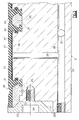
- the die 2 comprises a metal body 20 to be fixed to the lower plate 44 of the ceramic mould and comprising a series of through horizontal ducts 27, two in number in the illustrated embodiment (Figure 2), which are closed at one end whereas at their other end are connected to the pipe 30 ( Figure 1).
- Each individual hole 28 opens into the centre of the top of a circular raised portion 61 pertaining to a plurality of raised portions 61 uniformly distributed over the upper (or active) face of the body 20.
- each line or column of said plurality are offset from the raised portions 61 of the immediately adjacent lines or columns.
- Said raised portions can be replaced by projections of another shape, such as crossed ribs.
- a perforated metal slab 21 having substantially the same plan configuration as the upper face of the body 20 is fixed by rear locking members 25 ( Figure 3) such as screws, to the upper face of the body 20 from which said raised portions 61 rise.
- Said slab 21 is provided with a number of holes equal in number to the raised portions 61, the inner diameter of said holes being greater than the outer diameter of the raised portions 61 (see Figures 2, 3).
- the thickness of the slab 21 is practically equal to the height of the raised portions 61.
- edges of said holes are flared upwards and comprise a lower recess defining an anchoring ledge for an overlying slab 22 of suitable material, such as vulcanized rubber or other equivalent elastomer, hereinafter also known as the membrane.
- the depth of said chamber 60 is very small (see Figure 3), for example it can be practically zero, the seal being provided by a lateral gasket 62 associated with the respective raised portion 61.
- said grooves 63 can be arranged in ray formation or can consist of a single spiral-shaped groove.
- the upper peripheral region of the body 20 is surrounded by a perimetral recess 200 (see Figure 3) receiving a perimetral frame 23 fixed by screws indicated schematically by 24.
- the flat upper edge of said frame 23 is flush with the perimetral edge of the membrane 22, the constituent elements of said frame 23 having a transverse shape specular about the longitudinal axis of said screws 24.
- the aforedescribed plant implements the method of the invention as follows.
- the piston After unloading the formed tile 99 and charging the mould with the material 78 to be pressed, the piston is enabled to descend, by which the material 78 present in the cavity 46 is pressed.
- the chambers 60 do not contain oil, but before the pressing is complete, and more specifically when the pressure of the oil present in the operating chamber 13 reaches the set value of said valve 41, this valve opens to allow oil to pass.
- the measurements are made along bands parallel to the conveying direction in that any defects in charging the material 78 are distributed in said direction.
- the central processor 174 processes the travel amplitudes of each roller 74, displaying the data on the respective display 77 and converting them into commands for adjusting the charging parameters.
- the differences between said amplitudes are an indication of a shape defect in the tile, which defect can be practically eliminated by modifying the charging of the cavity 46, in particular the distribution of the material 78 within the cavity.
- each roller 74 deviate from each other by a quantity less than the allowable, ie 0.2-0.3 mm, the tile 99 is acceptable in practice.
- the adjustment occurs automatically by varying the parameters concerned, ie the carriage speed, the the mutual arrangement and inclination of its flaps 16, and the moment in which the lower die defining the mould cavity begins to descend.
- All said adjustments are preferably made during successive cycles, ie for successive tiles, until a statistically acceptable charging is achieved.
Landscapes
- Engineering & Computer Science (AREA)
- Mechanical Engineering (AREA)
- Chemical & Material Sciences (AREA)
- Ceramic Engineering (AREA)
- Manufacturing & Machinery (AREA)
- Press-Shaping Or Shaping Using Conveyers (AREA)
- Devices For Post-Treatments, Processing, Supply, Discharge, And Other Processes (AREA)
Applications Claiming Priority (2)
| Application Number | Priority Date | Filing Date | Title |
|---|---|---|---|
| ITRE930089 | 1993-12-21 | ||
| ITRE930089A IT1262344B (it) | 1993-12-21 | 1993-12-21 | Metodo e impianto per la formatura di piastrelle a compattazione e spessore uniformi, e piastrelle cosi' ottenute. |
Publications (2)
| Publication Number | Publication Date |
|---|---|
| EP0659527A1 true EP0659527A1 (de) | 1995-06-28 |
| EP0659527B1 EP0659527B1 (de) | 2000-03-22 |
Family
ID=11398485
Family Applications (1)
| Application Number | Title | Priority Date | Filing Date |
|---|---|---|---|
| EP94203545A Expired - Lifetime EP0659527B1 (de) | 1993-12-21 | 1994-12-06 | Verfahren und Vorrichtung zur Herstellung von Fliesen mit konstanter Dichte und gleichbleibender Dicke und so hergestellte Fliesen |
Country Status (5)
| Country | Link |
|---|---|
| EP (1) | EP0659527B1 (de) |
| AT (1) | ATE190899T1 (de) |
| DE (1) | DE69423583T2 (de) |
| ES (1) | ES2142909T3 (de) |
| IT (1) | IT1262344B (de) |
Cited By (15)
| Publication number | Priority date | Publication date | Assignee | Title |
|---|---|---|---|---|
| EP0701889A3 (de) * | 1994-09-13 | 1996-07-10 | Maris Algeri | Form zum isostatischen Pressen von Keramikfliesen und Verfahren zum Herstelllen der Fliesen |
| EP0893217A1 (de) * | 1997-07-21 | 1999-01-27 | Iberditan S.L. | Isostatischer Pressstempel zum Herstellen keramischer Fliesenrohlinge und Presse mit diesem Pressstempel |
| ES2181514A1 (es) * | 1999-07-15 | 2003-02-16 | Rodriguez Constantino Parra | Dispositivo para regular la compactacion en punzones para prensas. |
| EP1354679A1 (de) * | 2002-04-18 | 2003-10-22 | Euroditan S.L. | Vorrichtung zur automatischen Korrektur der Dichte von keramischen Fliesenrohlingen |
| EP1510311A1 (de) * | 2003-08-23 | 2005-03-02 | Euroditan S.L. | Verfahren zur Herstellung keramischer Fliesen |
| WO2005068143A1 (fr) * | 2003-10-29 | 2005-07-28 | Jimian Chen | Equipement de distribution de materiau a tuyaux multiples pour le compactage de tuiles et procede de distribution |
| EP1704975A3 (de) * | 2005-03-25 | 2007-07-04 | C.B.M. - S.r.l. | Pressstempel zur Prägung von Keramikgegenständen |
| EP1716998A3 (de) * | 2005-04-26 | 2007-11-07 | Sacmi Cooperativa Meccanici Imola Societa' Cooperativa | Verdichtungsüberwachungssystem für eine isostatische Presse |
| CN100463788C (zh) * | 2005-11-03 | 2009-02-25 | 唐君 | 一种仿大理石线条的陶瓷砖的布料方法及布料设备 |
| WO2009101500A1 (en) * | 2008-02-15 | 2009-08-20 | Sacmi Cooperativa Meccanici Imola Societa' Cooperativa | Pressing apparatus and method |
| IT201900013497A1 (it) * | 2019-07-31 | 2021-01-31 | Officina Ferrari Carlo Spa | Metodo di controllo della formatura di piastrelle ceramiche e relativo dispositivo di formatura |
| CN113910428A (zh) * | 2021-10-15 | 2022-01-11 | 清远市榕兴新型环保建材有限责任公司 | 一种加气砖加工成型装置 |
| CN115366227A (zh) * | 2022-08-08 | 2022-11-22 | 四会市大美地新材料有限公司 | 一种砖坯成型工艺 |
| CN116100656A (zh) * | 2023-03-28 | 2023-05-12 | 铜陵优必胜新材料科技有限公司 | 一种陶瓷片覆膜定型装置、生产线及定型方法 |
| US20250162196A1 (en) * | 2023-11-20 | 2025-05-22 | Xtile S.R.L. | Process for forming tiles and isostatic punch for forming tiles |
Citations (7)
| Publication number | Priority date | Publication date | Assignee | Title |
|---|---|---|---|---|
| US3044137A (en) * | 1960-02-29 | 1962-07-17 | George E Kanta | Device for controlling the height and density of building blocks |
| US3079661A (en) * | 1961-03-06 | 1963-03-05 | Crossley Machine Company Inc | Automatic thickness control means for flat products |
| US3109927A (en) * | 1961-04-20 | 1963-11-05 | Florida Tile Ind Inc | Tile size responsive apparatus and control |
| US3604075A (en) * | 1969-01-27 | 1971-09-14 | Stearns Mfg Co | Density control system for block-making apparatus |
| US3963397A (en) * | 1974-06-03 | 1976-06-15 | Besser Company | Cementitious product making system with product height gauging mechanism |
| FR2403792A1 (fr) * | 1977-09-22 | 1979-04-20 | Fette Wilhelm Gmbh | Procede pour la fabrication de comprimes et presse a confectionner les comprimes |
| EP0392593A2 (de) * | 1989-04-12 | 1990-10-17 | Iberditan, S.L. | Vorrichtung zur selbsttätigen Korrektur der Pressdichte bei der Herstellung von Dachziegeln |
-
1993
- 1993-12-21 IT ITRE930089A patent/IT1262344B/it active IP Right Grant
-
1994
- 1994-12-06 EP EP94203545A patent/EP0659527B1/de not_active Expired - Lifetime
- 1994-12-06 AT AT94203545T patent/ATE190899T1/de not_active IP Right Cessation
- 1994-12-06 ES ES94203545T patent/ES2142909T3/es not_active Expired - Lifetime
- 1994-12-06 DE DE69423583T patent/DE69423583T2/de not_active Expired - Fee Related
Patent Citations (7)
| Publication number | Priority date | Publication date | Assignee | Title |
|---|---|---|---|---|
| US3044137A (en) * | 1960-02-29 | 1962-07-17 | George E Kanta | Device for controlling the height and density of building blocks |
| US3079661A (en) * | 1961-03-06 | 1963-03-05 | Crossley Machine Company Inc | Automatic thickness control means for flat products |
| US3109927A (en) * | 1961-04-20 | 1963-11-05 | Florida Tile Ind Inc | Tile size responsive apparatus and control |
| US3604075A (en) * | 1969-01-27 | 1971-09-14 | Stearns Mfg Co | Density control system for block-making apparatus |
| US3963397A (en) * | 1974-06-03 | 1976-06-15 | Besser Company | Cementitious product making system with product height gauging mechanism |
| FR2403792A1 (fr) * | 1977-09-22 | 1979-04-20 | Fette Wilhelm Gmbh | Procede pour la fabrication de comprimes et presse a confectionner les comprimes |
| EP0392593A2 (de) * | 1989-04-12 | 1990-10-17 | Iberditan, S.L. | Vorrichtung zur selbsttätigen Korrektur der Pressdichte bei der Herstellung von Dachziegeln |
Cited By (17)
| Publication number | Priority date | Publication date | Assignee | Title |
|---|---|---|---|---|
| EP0701889A3 (de) * | 1994-09-13 | 1996-07-10 | Maris Algeri | Form zum isostatischen Pressen von Keramikfliesen und Verfahren zum Herstelllen der Fliesen |
| EP0893217A1 (de) * | 1997-07-21 | 1999-01-27 | Iberditan S.L. | Isostatischer Pressstempel zum Herstellen keramischer Fliesenrohlinge und Presse mit diesem Pressstempel |
| ES2181514A1 (es) * | 1999-07-15 | 2003-02-16 | Rodriguez Constantino Parra | Dispositivo para regular la compactacion en punzones para prensas. |
| EP1354679A1 (de) * | 2002-04-18 | 2003-10-22 | Euroditan S.L. | Vorrichtung zur automatischen Korrektur der Dichte von keramischen Fliesenrohlingen |
| EP1510311A1 (de) * | 2003-08-23 | 2005-03-02 | Euroditan S.L. | Verfahren zur Herstellung keramischer Fliesen |
| WO2005068143A1 (fr) * | 2003-10-29 | 2005-07-28 | Jimian Chen | Equipement de distribution de materiau a tuyaux multiples pour le compactage de tuiles et procede de distribution |
| EP1704975A3 (de) * | 2005-03-25 | 2007-07-04 | C.B.M. - S.r.l. | Pressstempel zur Prägung von Keramikgegenständen |
| EP1716998A3 (de) * | 2005-04-26 | 2007-11-07 | Sacmi Cooperativa Meccanici Imola Societa' Cooperativa | Verdichtungsüberwachungssystem für eine isostatische Presse |
| CN100463788C (zh) * | 2005-11-03 | 2009-02-25 | 唐君 | 一种仿大理石线条的陶瓷砖的布料方法及布料设备 |
| WO2009101500A1 (en) * | 2008-02-15 | 2009-08-20 | Sacmi Cooperativa Meccanici Imola Societa' Cooperativa | Pressing apparatus and method |
| IT201900013497A1 (it) * | 2019-07-31 | 2021-01-31 | Officina Ferrari Carlo Spa | Metodo di controllo della formatura di piastrelle ceramiche e relativo dispositivo di formatura |
| CN113910428A (zh) * | 2021-10-15 | 2022-01-11 | 清远市榕兴新型环保建材有限责任公司 | 一种加气砖加工成型装置 |
| CN115366227A (zh) * | 2022-08-08 | 2022-11-22 | 四会市大美地新材料有限公司 | 一种砖坯成型工艺 |
| CN115366227B (zh) * | 2022-08-08 | 2024-04-09 | 四会市大美地新材料有限公司 | 一种砖坯成型工艺 |
| CN116100656A (zh) * | 2023-03-28 | 2023-05-12 | 铜陵优必胜新材料科技有限公司 | 一种陶瓷片覆膜定型装置、生产线及定型方法 |
| US20250162196A1 (en) * | 2023-11-20 | 2025-05-22 | Xtile S.R.L. | Process for forming tiles and isostatic punch for forming tiles |
| US12491659B2 (en) * | 2023-11-20 | 2025-12-09 | Xtile S.R.L. | Process for forming tiles and isostatic punch for forming tiles |
Also Published As
| Publication number | Publication date |
|---|---|
| EP0659527B1 (de) | 2000-03-22 |
| DE69423583T2 (de) | 2000-08-03 |
| ATE190899T1 (de) | 2000-04-15 |
| ES2142909T3 (es) | 2000-05-01 |
| DE69423583D1 (de) | 2000-04-27 |
| IT1262344B (it) | 1996-06-19 |
| ITRE930089A1 (it) | 1995-06-21 |
| ITRE930089A0 (it) | 1993-12-21 |
Similar Documents
| Publication | Publication Date | Title |
|---|---|---|
| EP0659527B1 (de) | Verfahren und Vorrichtung zur Herstellung von Fliesen mit konstanter Dichte und gleichbleibender Dicke und so hergestellte Fliesen | |
| CN106041770B (zh) | 全自动回转式多工位砂轮成型机 | |
| JP2005254330A (ja) | タブレット成形機及びタブレット成形機の制御方法 | |
| US3555599A (en) | Apparatus for shaping of granular substances | |
| US3811808A (en) | Weighed charge system for a brick press | |
| US5082438A (en) | Press for manufacturing stones | |
| EP1541327A1 (de) | Pulververdichtungsverfahren und pulververdichtungssystem | |
| EP0392593B1 (de) | Vorrichtung zur selbsttätigen Korrektur der Pressdichte bei der Herstellung von Dachziegeln | |
| US3970223A (en) | Material metering units | |
| US4036574A (en) | Device for the production of carbon bodies | |
| EP1136211B1 (de) | Vorrichtung zum Herstellen von keramischen Gegenständen wie zum Beispiel Platten , Fliesen und ähnlichen Artikeln durch Pressen von Pulver | |
| US4354811A (en) | Workpiece pellet length control apparatus | |
| US3397435A (en) | Attachment for a brick press | |
| US2706843A (en) | Method for molding plastic materials | |
| US20050189668A1 (en) | Method and apparatus for producing concrete blocks | |
| JPH073894U (ja) | 粉体充填装置 | |
| CN109808051A (zh) | 一种改善瓷砖尺寸差的布料补偿器 | |
| CN110524681B (zh) | 一种压砖机填料高度调节机构 | |
| WO1988006084A1 (en) | Method and device for die-casting of concrete products such as block stones in a cellular mould | |
| DE19731146C1 (de) | Isostatischer Preßstempel zum Herstellen keramischer Fliesenrohlinge und Presse mit diesem Preßstempel | |
| EP0324530B1 (de) | Verfahren zum Herstellen von Steinen in einer Presse und Presse zum Herstellen gennanter Steine | |
| RU2044638C1 (ru) | Установка для прессования изделий из строительных смесей | |
| JP3341447B2 (ja) | 粉末圧縮成形装置 | |
| CN120396092B (zh) | 一种混凝土砖块压制成型装置 | |
| CN117601227B (zh) | 陶瓷匣钵成型液压设备 |
Legal Events
| Date | Code | Title | Description |
|---|---|---|---|
| PUAI | Public reference made under article 153(3) epc to a published international application that has entered the european phase |
Free format text: ORIGINAL CODE: 0009012 |
|
| AK | Designated contracting states |
Kind code of ref document: A1 Designated state(s): AT BE CH DE DK ES FR GB GR IE IT LI LU MC NL PT SE |
|
| RAX | Requested extension states of the european patent have changed |
Free format text: LT PAYMENT 941207;SI PAYMENT 941207 |
|
| 17P | Request for examination filed |
Effective date: 19951219 |
|
| GRAG | Despatch of communication of intention to grant |
Free format text: ORIGINAL CODE: EPIDOS AGRA |
|
| 17Q | First examination report despatched |
Effective date: 19990302 |
|
| GRAG | Despatch of communication of intention to grant |
Free format text: ORIGINAL CODE: EPIDOS AGRA |
|
| GRAH | Despatch of communication of intention to grant a patent |
Free format text: ORIGINAL CODE: EPIDOS IGRA |
|
| GRAH | Despatch of communication of intention to grant a patent |
Free format text: ORIGINAL CODE: EPIDOS IGRA |
|
| GRAA | (expected) grant |
Free format text: ORIGINAL CODE: 0009210 |
|
| AK | Designated contracting states |
Kind code of ref document: B1 Designated state(s): AT BE CH DE DK ES FR GB GR IE IT LI LU MC NL PT SE |
|
| AX | Request for extension of the european patent |
Free format text: LT PAYMENT 19941207;SI PAYMENT 19941207 |
|
| LTIE | Lt: invalidation of european patent or patent extension | ||
| PG25 | Lapsed in a contracting state [announced via postgrant information from national office to epo] |
Ref country code: SE Free format text: THE PATENT HAS BEEN ANNULLED BY A DECISION OF A NATIONAL AUTHORITY Effective date: 20000322 Ref country code: NL Free format text: LAPSE BECAUSE OF FAILURE TO SUBMIT A TRANSLATION OF THE DESCRIPTION OR TO PAY THE FEE WITHIN THE PRESCRIBED TIME-LIMIT Effective date: 20000322 Ref country code: LI Free format text: LAPSE BECAUSE OF NON-PAYMENT OF DUE FEES Effective date: 20000322 Ref country code: GR Free format text: LAPSE BECAUSE OF NON-PAYMENT OF DUE FEES Effective date: 20000322 Ref country code: FR Free format text: LAPSE BECAUSE OF FAILURE TO SUBMIT A TRANSLATION OF THE DESCRIPTION OR TO PAY THE FEE WITHIN THE PRESCRIBED TIME-LIMIT Effective date: 20000322 Ref country code: CH Free format text: LAPSE BECAUSE OF NON-PAYMENT OF DUE FEES Effective date: 20000322 Ref country code: BE Free format text: LAPSE BECAUSE OF FAILURE TO SUBMIT A TRANSLATION OF THE DESCRIPTION OR TO PAY THE FEE WITHIN THE PRESCRIBED TIME-LIMIT Effective date: 20000322 Ref country code: AT Free format text: LAPSE BECAUSE OF FAILURE TO SUBMIT A TRANSLATION OF THE DESCRIPTION OR TO PAY THE FEE WITHIN THE PRESCRIBED TIME-LIMIT Effective date: 20000322 |
|
| REF | Corresponds to: |
Ref document number: 190899 Country of ref document: AT Date of ref document: 20000415 Kind code of ref document: T |
|
| REG | Reference to a national code |
Ref country code: CH Ref legal event code: EP |
|
| REF | Corresponds to: |
Ref document number: 69423583 Country of ref document: DE Date of ref document: 20000427 |
|
| REG | Reference to a national code |
Ref country code: ES Ref legal event code: FG2A Ref document number: 2142909 Country of ref document: ES Kind code of ref document: T3 |
|
| REG | Reference to a national code |
Ref country code: IE Ref legal event code: FG4D |
|
| ITF | It: translation for a ep patent filed | ||
| PG25 | Lapsed in a contracting state [announced via postgrant information from national office to epo] |
Ref country code: DK Free format text: LAPSE BECAUSE OF FAILURE TO SUBMIT A TRANSLATION OF THE DESCRIPTION OR TO PAY THE FEE WITHIN THE PRESCRIBED TIME-LIMIT Effective date: 20000622 |
|
| PG25 | Lapsed in a contracting state [announced via postgrant information from national office to epo] |
Ref country code: PT Free format text: LAPSE BECAUSE OF FAILURE TO SUBMIT A TRANSLATION OF THE DESCRIPTION OR TO PAY THE FEE WITHIN THE PRESCRIBED TIME-LIMIT Effective date: 20000623 |
|
| EN | Fr: translation not filed | ||
| NLV1 | Nl: lapsed or annulled due to failure to fulfill the requirements of art. 29p and 29m of the patents act | ||
| REG | Reference to a national code |
Ref country code: CH Ref legal event code: PL |
|
| PG25 | Lapsed in a contracting state [announced via postgrant information from national office to epo] |
Ref country code: LU Free format text: LAPSE BECAUSE OF NON-PAYMENT OF DUE FEES Effective date: 20001206 Ref country code: IE Free format text: LAPSE BECAUSE OF NON-PAYMENT OF DUE FEES Effective date: 20001206 Ref country code: GB Free format text: LAPSE BECAUSE OF NON-PAYMENT OF DUE FEES Effective date: 20001206 |
|
| PG25 | Lapsed in a contracting state [announced via postgrant information from national office to epo] |
Ref country code: MC Free format text: THE PATENT HAS BEEN ANNULLED BY A DECISION OF A NATIONAL AUTHORITY Effective date: 20001231 |
|
| PLBE | No opposition filed within time limit |
Free format text: ORIGINAL CODE: 0009261 |
|
| STAA | Information on the status of an ep patent application or granted ep patent |
Free format text: STATUS: NO OPPOSITION FILED WITHIN TIME LIMIT |
|
| 26N | No opposition filed | ||
| GBPC | Gb: european patent ceased through non-payment of renewal fee |
Effective date: 20001206 |
|
| REG | Reference to a national code |
Ref country code: IE Ref legal event code: MM4A |
|
| PGFP | Annual fee paid to national office [announced via postgrant information from national office to epo] |
Ref country code: ES Payment date: 20051121 Year of fee payment: 12 |
|
| PGFP | Annual fee paid to national office [announced via postgrant information from national office to epo] |
Ref country code: DE Payment date: 20051228 Year of fee payment: 12 |
|
| PGFP | Annual fee paid to national office [announced via postgrant information from national office to epo] |
Ref country code: IT Payment date: 20061231 Year of fee payment: 13 |
|
| PG25 | Lapsed in a contracting state [announced via postgrant information from national office to epo] |
Ref country code: DE Free format text: LAPSE BECAUSE OF NON-PAYMENT OF DUE FEES Effective date: 20070703 |
|
| REG | Reference to a national code |
Ref country code: ES Ref legal event code: FD2A Effective date: 20061207 |
|
| PG25 | Lapsed in a contracting state [announced via postgrant information from national office to epo] |
Ref country code: ES Free format text: LAPSE BECAUSE OF NON-PAYMENT OF DUE FEES Effective date: 20061207 |
|
| PG25 | Lapsed in a contracting state [announced via postgrant information from national office to epo] |
Ref country code: IT Free format text: LAPSE BECAUSE OF NON-PAYMENT OF DUE FEES Effective date: 20071206 |