EP0659570A2 - Mustererzeugungsgerät und Mustererzeugungsmethode - Google Patents
Mustererzeugungsgerät und Mustererzeugungsmethode Download PDFInfo
- Publication number
- EP0659570A2 EP0659570A2 EP94120557A EP94120557A EP0659570A2 EP 0659570 A2 EP0659570 A2 EP 0659570A2 EP 94120557 A EP94120557 A EP 94120557A EP 94120557 A EP94120557 A EP 94120557A EP 0659570 A2 EP0659570 A2 EP 0659570A2
- Authority
- EP
- European Patent Office
- Prior art keywords
- data
- pattern
- input data
- intermediate data
- input
- Prior art date
- Legal status (The legal status is an assumption and is not a legal conclusion. Google has not performed a legal analysis and makes no representation as to the accuracy of the status listed.)
- Granted
Links
Images


Classifications
-
- G—PHYSICS
- G06—COMPUTING OR CALCULATING; COUNTING
- G06K—GRAPHICAL DATA READING; PRESENTATION OF DATA; RECORD CARRIERS; HANDLING RECORD CARRIERS
- G06K15/00—Arrangements for producing a permanent visual presentation of the output data, e.g. computer output printers
-
- G—PHYSICS
- G06—COMPUTING OR CALCULATING; COUNTING
- G06K—GRAPHICAL DATA READING; PRESENTATION OF DATA; RECORD CARRIERS; HANDLING RECORD CARRIERS
- G06K2215/00—Arrangements for producing a permanent visual presentation of the output data
- G06K2215/0002—Handling the output data
- G06K2215/0005—Accepting output data; Preparing data for the controlling system
- G06K2215/0014—Transforming the printer input data into internal codes
-
- G—PHYSICS
- G06—COMPUTING OR CALCULATING; COUNTING
- G06K—GRAPHICAL DATA READING; PRESENTATION OF DATA; RECORD CARRIERS; HANDLING RECORD CARRIERS
- G06K2215/00—Arrangements for producing a permanent visual presentation of the output data
- G06K2215/0002—Handling the output data
- G06K2215/0062—Handling the output data combining generic and host data, e.g. filling a raster
- G06K2215/0065—Page or partial page composition
-
- G—PHYSICS
- G06—COMPUTING OR CALCULATING; COUNTING
- G06K—GRAPHICAL DATA READING; PRESENTATION OF DATA; RECORD CARRIERS; HANDLING RECORD CARRIERS
- G06K2215/00—Arrangements for producing a permanent visual presentation of the output data
- G06K2215/0082—Architecture adapted for a particular function
Definitions
- the present invention relates to a pattern output apparatus such as a printing apparatus or the like and a pattern output method, in which data received from an external apparatus such as a host computer or the like is developed as output information to bit map pattern data of a page unit and the bit map pattern data is outputted.
- such a kind of printing apparatus uses a general method whereby bit map pattern data of one page is developed into an image memory on the basis of input data (printer language such as a PDL or the like comprising a character code, a control code, and the like) received from a host computer and the result of the development in the image memory is converted to the video signal and is transferred to a printer mechanism section.
- input data printer language such as a PDL or the like comprising a character code, a control code, and the like
- a printing apparatus such that a plurality of print command systems are supported in one printing apparatus has been also generally widespread.
- the form to be overlaid into each page is the same form
- the form data is transmitted every page, it takes a data transfer time from the host computer. Therefore, generally, before the input data is transmitted, the form data is registered into a memory (for example, RAM) of the printing apparatus and the form data which has once been registered is held until the deletion is instructed from the host computer or a power source is cut off.
- a memory for example, RAM
- a secondary memory device such as a hard disc or the like
- registering form data into the secondary memory device a number of kinds of form data can be registered into the printing apparatus. Even if the power source is once cut off, the registered form data is not lost.
- a method whereby the form data is registered into the secondary memory device and a printing process is executed as mentioned above is becoming a general method.
- command systems for example, kind of PDL
- command system of the input data and the command system of the form have to be coincident.
- the conventional apparatus therefore, has a problem such that it is impossible to overlap the input data of a command system (A) and the form of a command system (B) and to produce and output a form overlay pattern.
- the printing apparatus has the command system (A) which is excellent for a text process (character process) and a command system (B) which is excellent in a graphic process, the result (form overlay pattern) in which the input data and the form are overlaid cannot be outputted by utilizing merits of those two command systems.
- a pattern output apparatus comprising: converting means for converting form data to intermediate data; memory means for storing the form data converted to the intermediate data by the converting means; and output control means for converting input data that is inputted from an external apparatus to intermediate data and for producing and outputting a pattern based on the input data converted to the intermediate data and the form data stored in the memory means.
- a pattern output method comprising the steps of: converting the form data registered in the pattern output apparatus mentioned above and the input data which is inputted from the external apparatus to the same intermediate data; and producing and outputting a pattern based on the input data converted to the intermediate data and the form data.
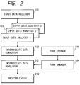
- Figs. 1 and 2 are schematic block diagrams showing functional constructions of a printing apparatus according to the invention.
- reference numeral 101 denotes an input data receiver for receiving input data (for example, printer language such as a PDL or the like comprising a character code, a control code, and the like) transmitted from a host computer.
- input data for example, printer language such as a PDL or the like comprising a character code, a control code, and the like
- the input data comprises: data such as character code, figure, image, etc. for actually executing a printing process; and a control code for designating a printing position, a size, or the like and for designating a switching control of, for instance, a sheet feed mode (cassette sheet feed, manual sheet insertion), a sheet delivery mode, and one-side/both-sides printing mode.
- a sheet feed mode cassette sheet feed, manual sheet insertion
- a sheet delivery mode for one-side/both-sides printing mode.
- Reference numeral 102 denotes an input data analyzer (program) for analyzing input data received to the input data receiver 101.
- the input data analyzer 102 is built in every command system.
- the input data analyzer 102 includes: an input data analyzer (A) for analyzing input data (A) (command system A); and an input data analyzer (B) for analyzing input data (B) (command system B).
- Reference numeral 103 denotes an intermediate data converter for converting the input data analyzed by the input data analyzer 102 to the intermediate data that is peculiar to the printing apparatus on a page unit basis.
- the intermediate data denotes the data which is obtained by processing the input data so as to easily produce output data (bit map data) from the input data.
- Reference numeral 104 denotes a form manager for registering and managing the intermediate data, as a form, of one page which was converted by the intermediate data converter 103.
- Reference numeral 105 denotes a form storage (RAM) to store the forms registered by the form manager 104.
- RAM form storage
- Fig. 2 the component elements shown by reference numerals 101, 102, 103, 104, and 105 are the same as those shown in Fig. 1.
- Reference numeral 201 denotes an intermediate data developer for developing the intermediate data converted from the input data by the intermediate data converter 103 to the output data (bit map data) of one page.
- the intermediate data developer 201 also develops form information (intermediate data format) stored in the form storage 105 by overlapping the form into the bit map data produced from the input data through the form manager 104.
- Reference numerals 101 to 105 and 201 denote functions in a printer controller of the printing apparatus.
- Reference numeral 202 in Fig. 2 denotes an actual printing mechanism section (printer engine) comprising: a printing mechanism for performing a print control; and a control mechanism for executing a feeding control of a sheet feeding system (sheet feeding mode, sheet delivery process) in the printer engine.
- FIG. 3 A fundamental concept of the invention is shown in Fig. 3.
- Fig. 3 shows a general example of the overlap of input data and a form.
- reference numeral 301 shows a state in which input data transmitted from the host computer is received by the input data receiver 101 and is transmitted through the input data analyzer 102 and intermediate data converter 103 and bit map data is developed in a memory of one page in the intermediate data developer 201.
- Reference numeral 302 in Fig. 3 shows a state in which the form registered in the form storage 105 by the function shown in Fig. 1 is developed to the bit map data into the memory of one page in the intermediate data developer 201 by the form manager 104.
- the input data 301 When the input data 301 is received by the input data receiver 101, the input data 301 comprises the data according to the command system (A) which is excellent for a text process. A command of the input data 301 is analyzed by the input data analyzer 102 corresponding to the command system (A) and the input data 301 is developed to the bit map data of one page.
- the form 302 when the form 302 is received by the input data receiver 101, the form 302 comprises the data according to the command system (B) which is excellent for a graphic process.
- a command of the form 302 is analyzed by the input data analyzer 102 corresponding to the command system (B).
- the form is registered into the form storage 105 as a form in the intermediate data format of one page. After that, the form is developed as bit map data into the memory of one page in the intermediate data developer 201 by the form manager 104.
- Reference numeral 303 in Fig. 3 denotes an output result (form overlay pattern) which is actually outputted by overlapping the bit map data 301 as a character pattern and the bit map data 302 as form data by the intermediate data developer 201 in Fig. 2.
- Figs. 4 and 5 show a general construction in the printing apparatus.
- Reference numeral 401 in Fig. 4 denotes a host computer for transmitting various input data to the printing apparatus.
- reference numeral 402 denotes an example of the printing apparatus in the invention (a laser beam printer using a laser beam as a light emitting device is show here); 403 a printer controller of the printing apparatus; and 404 a printing mechanism unit (printer engine) of the printing apparatus.
- reference numeral 405 denotes a control section for controlling whole portions in the printer engine 404 of Fig. 4.
- the control section 405 comprises: a portion for receiving a video signal from the printer controller 403 in Fig. 4, for receiving a control command from the printer controller, and for transmitting status information of the engine to the printer controller; and a portion for controlling an electronic photographing process, the sheet feeding system, and the optical system.
- Reference numeral 406 in Fig. 4 denotes an optical system in the printer engine 404 in Fig. 4.
- reference numeral 407 denotes the electronic photographing process and sheet feeding system in the printer engine 404 in Fig. 4.
- Reference numeral 408 in Fig. 4 denotes an operation panel which can input a command to designate various operations in the printing apparatus.
- Fig. 5 shows a further detailed diagram of the sheet feeding system 407 in Fig. 4.
- reference numeral 501 denotes a feed cassette and 502 indicates a feed roller to feed sheets from the sheet cassette one by one.
- reference numeral 503 denotes a photosensitive drum and 504 indicates a fixing unit.
- reference numeral 505 in Fig. 5 denotes a feeding state of the sheet in the sheet feeding system.
- Fig. 6 shows a block diagram of the printer controller 403 in Fig. 4.
- reference numeral 601 denotes a central processing unit (CPU) to control the whole printer controller and 602 indicates a program memory in which programs (including control programs shown in flowcharts of Figs. 9 and 10, which will be explained hereinlater) for controlling the printer controller have been stored.
- the program memory 602 is constructed by an ROM (read only memory).
- Reference numeral 603 denotes a memory in which font information (dot font, outline font) to develop the character code to the bit map has been stored.
- the memory 603 is constructed by an ROM (read only memory).
- Reference numeral 604 denotes a hardware circuit for transferring the bit map data obtained by developing the input data to the printer engine.
- the hardware circuit 604 comprises, for example, a DMAC (direct memory access controller) or an FIFO.
- Reference numeral 605 denotes a data input interface circuit (hereinafter, simply referred to as an input I/F) for connecting the host computer (401 in Fig. 6) and the printer controller (403 in Fig. 6).
- Reference numeral 606 denotes a work memory which is necessary for making the control program in the ROM 602 operative.
- the work memory 606 is constructed by an RAM (random access memory).
- a storage area of the input data, a development area of the input data, and the like are also provided in the work memory 606.
- Reference numeral 607 denotes a data output interface circuit (hereinafter, simply referred to as an output I/F) for connecting the printer controller (403 in Fig. 6) and the printer engine (404 in Fig. 6).
- Reference numeral 608 denotes an image signal generator for generating a video signal from the bit map data developed in the input data development area (606 in Fig. 6) synchronously with the printer engine (404 in Fig. 6).
- Reference numeral 609 denotes a panel interface circuit (hereinafter, simply referred to as a panel I/F) for connecting the operation panel (408 in Fig. 6) and the printer controller (403 in Fig. 6).
- Reference numeral 610 denotes an internal bus for connecting each of the above memories and circuits to the CPU 601.
- the form information transmitted from the host computer is converted to the intermediate print data and, after that, it is stored as form information (703 in Fig. 7) into the work memory (606) in the printing apparatus by an intermediate data format.
- the various form information (703 in Fig. 7) stored in the work memory (606) is managed by a form management table (RAM) as shown at 701 in Fig. 7.
- RAM form management table
- reference numeral 702 denotes a management record for each form information (703 in Fig. 7) in the form management table (701 in Fig. 7).
- Fig. 8 shows a detailed format of the management record 702 in Fig. 7.
- Reference numeral 801 in Fig. 8 denotes a form name designated when the host computer registers the form into the printing apparatus; 802 indicates an ID flag to discriminate whether the management record is valid or invalid; and 803 an address pointer when the form information has been stored into the work memory (606).
- the CPU 601 judges whether the form information from the host computer 401 has been received by the input data receiver 101 or not (step S1).
- the form information which is received from the host computer 401 is constructed by: a form registration start command 901; form data 902 (comprising form data and ID information indicative of a form name or the like to discriminate the form data); and a form registration end command 903.
- the form information differs every printer language.
- the form information of a printer language (A) of the command system (A) differs from the form information of a printer language (B) of the command system (B).
- the form data comprises: a character code, a figure, or an image; and a control code to designate the printing position and the like.
- step S1 by discriminating whether the form registration start command 901 has been received or not, a check is made to see if the form information has been received or the input data has been received.
- the form data 902 is stored in the work memory 606 until the form registration end command 903 is received.
- a process for analyzing the form information is executed by the input data analyzer 102 in accordance with the command system corresponding to the form information received in step S1 and the form information is converted to the intermediate data by the intermediate data converter 103 (step S2 in Fig. 10).
- the intermediate data converted in step S2 is stored into the work memory (606) (S3 in Fig. 10).
- a nonused record in the form management table is searched (step S4 in Fig. 10).
- step S4 step S5 in Fig. 10
- step S5 step S5 in Fig. 10
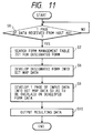
- the CPU 601 judges whether the input data of one page has been received from the host computer 401 or not (step S6). If YES, the CPU 601 analyzes the input data in accordance with the command system corresponding to the input data which has been transmitted from the host computer and received by the input data receiver 101. The CPU 601 converts the input data of one page to the intermediate data.
- the form registered in the work memory of the printing apparatus is found out by searching the form name 801 in the form management record in the form management table (step S7 in Fig. 11).
- the form data (form data in the intermediate data format) is subsequently read out by accessing to the address pointer 803 of the form management record of the form file which was found out in step S7 and the form data is actually developed to the bit map data (step S8 in Fig. 11).
- the intermediate data obtained by converting the input data is overlapped to the bit map data of the form data which was developed in step S8 and is developed (step S9 in Fig. 11), thereby producing the form overlay pattern.
- the form overlay pattern is transferred to the bit map output section and is printed and outputted (step S10 in Fig. 11). Or, the produced form overlay pattern (303 in Fig. 3, for instance) can be also displayed and outputted to a display apparatus such as a CRT or the like.
- the method of converting the form data to the intermediate data and storing into the work memory has been used.
- a hard disc (1101), an IC card, or the like as a secondary memory device as shown in Fig. 12, the intermediate data of the form data can be also stored into the secondary memory device.
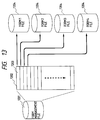
- the form data included in the form information transmitted from the host computer is converted to the intermediate data and stored as a form file (1204 in Fig. 13) into the secondary memory device (1101).
- FIG. 13 Various form files (1204 in Fig. 13) stored in the secondary memory device (1101) are managed by a file management file as shown at 1201 in Fig. 13 and the form management file itself is stored into the secondary memory device (1101).
- Reference numeral 1202 in Fig. 13 denotes a management record (1203 in Fig. 13) for each form file (1204 in Fig. 13) of the form management file (1201 in Fig. 13).
- Fig. 14 shows a detailed format of the management record (203) in Fig. 13.
- Reference numeral 1301 in Fig. 14 denotes a form name designated when the host computer registers the form into the printing apparatus; 1302 an ID flag to discriminate whether the management record is valid or invalid; and 1303 a form file name when the form information is stored into the secondary memory device (1101).
- the invention can be realized in a readable/writable secondary memory device such as floppy disk, magnetooptic disk, or the like.
- the invention can be also realized by using a non-volatile memory.
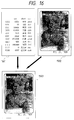
- a plurality of forms can be also overlapped into the input data of one page as shown in Figs. 15 and 16. Namely, in the input data analyzer of various command systems provided in the printing apparatus, by registering each form data as input data of the optimum command system, the optimum output result can be derived.
- reference numerals 1401, 1402, and 1403 in Fig. 15 show states in which form information of different command systems have been registered.
- Reference numeral 1502 in Fig. 16 shows a state in which the forms 1401, 1402, and 1403 have been overlapped and developed into the bit map.
- Reference numeral 1503 in Fig. 16 shows an output result (form overlay pattern) which is actually outputted by overlapping the bit map data of input data (1501 in Fig. 16) and the bit map data of the form data 1502.
- the bit map data of the page unit is converted to the video signal and is transferred from the input data developer to the printer engine or display mechanism (not shown) and is outputted.
- the printer engine can be applied to the following printing apparatuses.
- the printing apparatus corresponds to a plurality of command systems
- the input data and form data corresponding to various command systems to the intermediate print data that is peculiar to the printing apparatus, it is possible to overlap the input data of the command system (A) and the form data of the command system (B) and to produce and print or display the form overlay pattern.
- the result (form overlay pattern) in which the print data and form data are overlapped can be outputted.
- a pattern output apparatus and a pattern output method in which data received from an external apparatus such as a host computer is developed to bit map pattern data on a page unit basis as output information and the bit map pattern data is outputted.
- the pattern output apparatus comprises a converter for converting form data to intermediate data, a memory to store the form data converted to the intermediate data by the converter, and an output controller for converting input data which is inputted from an external apparatus to intermediate data, for producing a pattern based on the input data converted to the intermediate data and the form data stored in the memory, and for outputting the pattern.
- the input data and the form data are expressed by different command systems.
- the intermediate data has a data format peculiar to the pattern output apparatus.
- the intermediate data is the data obtained by processing the input data or form data so as to easily produce the pattern.
Landscapes
- Engineering & Computer Science (AREA)
- General Engineering & Computer Science (AREA)
- Physics & Mathematics (AREA)
- General Physics & Mathematics (AREA)
- Theoretical Computer Science (AREA)
- Record Information Processing For Printing (AREA)
Applications Claiming Priority (2)
| Application Number | Priority Date | Filing Date | Title |
|---|---|---|---|
| JP5331096A JPH07186485A (ja) | 1993-12-27 | 1993-12-27 | 印刷装置 |
| JP331096/93 | 1993-12-27 |
Publications (3)
| Publication Number | Publication Date |
|---|---|
| EP0659570A2 true EP0659570A2 (de) | 1995-06-28 |
| EP0659570A3 EP0659570A3 (de) | 1996-02-07 |
| EP0659570B1 EP0659570B1 (de) | 1999-05-26 |
Family
ID=18239815
Family Applications (1)
| Application Number | Title | Priority Date | Filing Date |
|---|---|---|---|
| EP94120557A Expired - Lifetime EP0659570B1 (de) | 1993-12-27 | 1994-12-23 | Mustererzeugungsgerät und Mustererzeugungsmethode |
Country Status (4)
| Country | Link |
|---|---|
| US (1) | US6331894B1 (de) |
| EP (1) | EP0659570B1 (de) |
| JP (1) | JPH07186485A (de) |
| DE (1) | DE69418687T2 (de) |
Cited By (5)
| Publication number | Priority date | Publication date | Assignee | Title |
|---|---|---|---|---|
| EP0782067A3 (de) * | 1995-11-30 | 1997-07-09 | Seiko Epson Corporation | Bildinformationsdrucksystem und -druckverfahren |
| EP0820004A1 (de) * | 1996-07-19 | 1998-01-21 | Seiko Epson Corporation | Druckersystem, Druckertreiber und Drucker |
| EP0867832A3 (de) * | 1997-03-25 | 2002-08-14 | Seiko Epson Corporation | Drucker, Druckverfahren und Druckrichtung |
| EP0849701A3 (de) * | 1996-12-20 | 2002-11-06 | Canon Kabushiki Kaisha | Druckersteuerungsgerät und -verfahren, Steuerungsprogramm speicherndes Speichermedium |
| US6665081B1 (en) | 1996-07-19 | 2003-12-16 | Seiko Epson Corporation | Print system printer driver and printer |
Families Citing this family (7)
| Publication number | Priority date | Publication date | Assignee | Title |
|---|---|---|---|---|
| JP2002321420A (ja) * | 2001-04-26 | 2002-11-05 | Oki Data Corp | 印刷装置 |
| JP2004174797A (ja) * | 2002-11-26 | 2004-06-24 | Fuji Xerox Co Ltd | 印刷制御プログラム、印刷制御システム及び印刷制御方法 |
| US7953769B1 (en) * | 2004-01-21 | 2011-05-31 | Computer Associates Think, Inc. | XML data packaging system and method |
| US7970801B1 (en) * | 2004-01-21 | 2011-06-28 | Computer Associates Think, Inc. | Data packaging system and method |
| US20050179945A1 (en) * | 2004-02-12 | 2005-08-18 | Sharp Laboratories Of America, Inc. | System and method for variable text overlay |
| US8121338B2 (en) | 2004-07-07 | 2012-02-21 | Directsmile Gmbh | Process for generating images with realistic text insertion |
| JP5686292B2 (ja) * | 2011-03-29 | 2015-03-18 | 富士ゼロックス株式会社 | 情報処理装置および処理プログラム |
Family Cites Families (12)
| Publication number | Priority date | Publication date | Assignee | Title |
|---|---|---|---|---|
| JPS6022234A (ja) * | 1983-07-18 | 1985-02-04 | Kanzaki Paper Mfg Co Ltd | フオ−ムオ−バ−レイ式プリント装置 |
| GB2220511B (en) * | 1988-07-08 | 1992-04-15 | Canon Kk | Recording control apparatus |
| JPH02136918A (ja) | 1988-11-17 | 1990-05-25 | Nec Field Service Ltd | 分散処理における書式オーバレイ出力処理方式 |
| JP2796628B2 (ja) * | 1988-11-29 | 1998-09-10 | カシオ計算機株式会社 | 印字装置 |
| JPH02185475A (ja) * | 1989-01-13 | 1990-07-19 | Casio Electron Mfg Co Ltd | 印字装置 |
| US5119465A (en) * | 1989-06-19 | 1992-06-02 | Digital Equipment Corporation | System for selectively converting plurality of source data structures through corresponding source intermediate structures, and target intermediate structures into selected target structure |
| US5465165A (en) * | 1991-06-11 | 1995-11-07 | Canon Kabushiki Kaisha | Image processing system |
| JPH05119937A (ja) | 1991-10-30 | 1993-05-18 | Chugoku Nippon Denki Software Kk | 書式オーバレイ装置 |
| US5469373A (en) * | 1992-02-14 | 1995-11-21 | Canon Kabushiki Kaisha | Printing apparatus and method that discriminates which analyzer should analyze information |
| JPH0671952A (ja) * | 1992-08-27 | 1994-03-15 | Brother Ind Ltd | 印字装置 |
| JP3266685B2 (ja) * | 1993-02-17 | 2002-03-18 | ブラザー工業株式会社 | プリンタ |
| US5530793A (en) * | 1993-09-24 | 1996-06-25 | Eastman Kodak Company | System for custom imprinting a variety of articles with images obtained from a variety of different sources |
-
1993
- 1993-12-27 JP JP5331096A patent/JPH07186485A/ja active Pending
-
1994
- 1994-12-23 DE DE69418687T patent/DE69418687T2/de not_active Expired - Lifetime
- 1994-12-23 EP EP94120557A patent/EP0659570B1/de not_active Expired - Lifetime
-
1997
- 1997-07-29 US US08/901,284 patent/US6331894B1/en not_active Expired - Lifetime
Cited By (7)
| Publication number | Priority date | Publication date | Assignee | Title |
|---|---|---|---|---|
| EP0782067A3 (de) * | 1995-11-30 | 1997-07-09 | Seiko Epson Corporation | Bildinformationsdrucksystem und -druckverfahren |
| US6104498A (en) * | 1995-11-30 | 2000-08-15 | Seiko Epson Corporation | Image information print system and method |
| EP0820004A1 (de) * | 1996-07-19 | 1998-01-21 | Seiko Epson Corporation | Druckersystem, Druckertreiber und Drucker |
| US6665081B1 (en) | 1996-07-19 | 2003-12-16 | Seiko Epson Corporation | Print system printer driver and printer |
| EP0849701A3 (de) * | 1996-12-20 | 2002-11-06 | Canon Kabushiki Kaisha | Druckersteuerungsgerät und -verfahren, Steuerungsprogramm speicherndes Speichermedium |
| US6611347B1 (en) | 1996-12-20 | 2003-08-26 | Canon Kabushiki Kaisha | Print control apparatus, print control method, storage medium, and computer readable program performing a form overlay process |
| EP0867832A3 (de) * | 1997-03-25 | 2002-08-14 | Seiko Epson Corporation | Drucker, Druckverfahren und Druckrichtung |
Also Published As
| Publication number | Publication date |
|---|---|
| US6331894B1 (en) | 2001-12-18 |
| DE69418687D1 (de) | 1999-07-01 |
| EP0659570B1 (de) | 1999-05-26 |
| DE69418687T2 (de) | 2000-03-02 |
| JPH07186485A (ja) | 1995-07-25 |
| EP0659570A3 (de) | 1996-02-07 |
Similar Documents
| Publication | Publication Date | Title |
|---|---|---|
| US6888641B2 (en) | Designating an image processing apparatus based on limited selection conditions | |
| US7064849B1 (en) | Data processing apparatus adaptable to plural environments and data processing method | |
| JPS63256450A (ja) | 出力装置 | |
| EP0659570B1 (de) | Mustererzeugungsgerät und Mustererzeugungsmethode | |
| US6977739B2 (en) | Printing apparatus and its control method | |
| US5483623A (en) | Printing apparatus | |
| US5915258A (en) | Apparatus and method for generating and outputting a list of a plurality of stored forms | |
| US6175426B1 (en) | Printing apparatus and print control method | |
| US5740462A (en) | Output apparatus permitting font selection based on resolutions | |
| US6700677B1 (en) | Printing apparatus, data output apparatus and computer readable memory medium | |
| JP4541577B2 (ja) | 画像形成装置、画像形成方法、画像形成システム、プログラムおよび記憶媒体 | |
| EP0554998A1 (de) | Verfahren und Vorrichtung zur Bildverarbeitung | |
| US6061070A (en) | Character outputting | |
| US7027170B1 (en) | Printing control system for separation printing | |
| EP0555841B1 (de) | Ausgabegerät | |
| US6633397B2 (en) | Output apparatus and output environment setting method in output apparatus | |
| US6629155B1 (en) | Data input/output method and apparatus and storage medium | |
| JP2526873B2 (ja) | 文字発生装置 | |
| JP2869923B2 (ja) | 印刷制御装置 | |
| JP3199544B2 (ja) | 印刷装置および印刷制御方法 | |
| JP2521918B2 (ja) | 文字発生装置 | |
| JPH07137367A (ja) | 画像処理装置 | |
| JP2891857B2 (ja) | 印刷装置および印刷方法 | |
| JP2002052790A (ja) | 画像形成装置および方法 | |
| JPH05338280A (ja) | 印刷方法及びその装置 |
Legal Events
| Date | Code | Title | Description |
|---|---|---|---|
| PUAI | Public reference made under article 153(3) epc to a published international application that has entered the european phase |
Free format text: ORIGINAL CODE: 0009012 |
|
| AK | Designated contracting states |
Kind code of ref document: A2 Designated state(s): DE ES FR GB IT NL |
|
| PUAL | Search report despatched |
Free format text: ORIGINAL CODE: 0009013 |
|
| AK | Designated contracting states |
Kind code of ref document: A3 Designated state(s): DE ES FR GB IT NL |
|
| 17P | Request for examination filed |
Effective date: 19960624 |
|
| 17Q | First examination report despatched |
Effective date: 19970418 |
|
| GRAG | Despatch of communication of intention to grant |
Free format text: ORIGINAL CODE: EPIDOS AGRA |
|
| GRAG | Despatch of communication of intention to grant |
Free format text: ORIGINAL CODE: EPIDOS AGRA |
|
| GRAH | Despatch of communication of intention to grant a patent |
Free format text: ORIGINAL CODE: EPIDOS IGRA |
|
| GRAH | Despatch of communication of intention to grant a patent |
Free format text: ORIGINAL CODE: EPIDOS IGRA |
|
| GRAA | (expected) grant |
Free format text: ORIGINAL CODE: 0009210 |
|
| AK | Designated contracting states |
Kind code of ref document: B1 Designated state(s): DE ES FR GB IT NL |
|
| PG25 | Lapsed in a contracting state [announced via postgrant information from national office to epo] |
Ref country code: NL Free format text: LAPSE BECAUSE OF FAILURE TO SUBMIT A TRANSLATION OF THE DESCRIPTION OR TO PAY THE FEE WITHIN THE PRESCRIBED TIME-LIMIT Effective date: 19990526 Ref country code: IT Free format text: LAPSE BECAUSE OF FAILURE TO SUBMIT A TRANSLATION OF THE DESCRIPTION OR TO PAY THE FEE WITHIN THE PRESCRIBED TIME-LIMIT;WARNING: LAPSES OF ITALIAN PATENTS WITH EFFECTIVE DATE BEFORE 2007 MAY HAVE OCCURRED AT ANY TIME BEFORE 2007. THE CORRECT EFFECTIVE DATE MAY BE DIFFERENT FROM THE ONE RECORDED. Effective date: 19990526 Ref country code: FR Free format text: LAPSE BECAUSE OF FAILURE TO SUBMIT A TRANSLATION OF THE DESCRIPTION OR TO PAY THE FEE WITHIN THE PRESCRIBED TIME-LIMIT Effective date: 19990526 Ref country code: ES Free format text: THE PATENT HAS BEEN ANNULLED BY A DECISION OF A NATIONAL AUTHORITY Effective date: 19990526 |
|
| REF | Corresponds to: |
Ref document number: 69418687 Country of ref document: DE Date of ref document: 19990701 |
|
| EN | Fr: translation not filed | ||
| PLBE | No opposition filed within time limit |
Free format text: ORIGINAL CODE: 0009261 |
|
| STAA | Information on the status of an ep patent application or granted ep patent |
Free format text: STATUS: NO OPPOSITION FILED WITHIN TIME LIMIT |
|
| 26N | No opposition filed | ||
| REG | Reference to a national code |
Ref country code: GB Ref legal event code: IF02 |
|
| PGFP | Annual fee paid to national office [announced via postgrant information from national office to epo] |
Ref country code: GB Payment date: 20121219 Year of fee payment: 19 |
|
| PGFP | Annual fee paid to national office [announced via postgrant information from national office to epo] |
Ref country code: DE Payment date: 20121231 Year of fee payment: 19 |
|
| REG | Reference to a national code |
Ref country code: DE Ref legal event code: R119 Ref document number: 69418687 Country of ref document: DE |
|
| GBPC | Gb: european patent ceased through non-payment of renewal fee |
Effective date: 20131223 |
|
| REG | Reference to a national code |
Ref country code: DE Ref legal event code: R119 Ref document number: 69418687 Country of ref document: DE Effective date: 20140701 |
|
| PG25 | Lapsed in a contracting state [announced via postgrant information from national office to epo] |
Ref country code: DE Free format text: LAPSE BECAUSE OF NON-PAYMENT OF DUE FEES Effective date: 20140701 |
|
| PG25 | Lapsed in a contracting state [announced via postgrant information from national office to epo] |
Ref country code: GB Free format text: LAPSE BECAUSE OF NON-PAYMENT OF DUE FEES Effective date: 20131223 |