EP0659617A1 - Système de retenue d'un occupant de véhicule - Google Patents
Système de retenue d'un occupant de véhicule Download PDFInfo
- Publication number
- EP0659617A1 EP0659617A1 EP94120112A EP94120112A EP0659617A1 EP 0659617 A1 EP0659617 A1 EP 0659617A1 EP 94120112 A EP94120112 A EP 94120112A EP 94120112 A EP94120112 A EP 94120112A EP 0659617 A1 EP0659617 A1 EP 0659617A1
- Authority
- EP
- European Patent Office
- Prior art keywords
- restraint
- panel
- vehicle
- detachable
- air bag
- Prior art date
- Legal status (The legal status is an assumption and is not a legal conclusion. Google has not performed a legal analysis and makes no representation as to the accuracy of the status listed.)
- Granted
Links
- 239000012530 fluid Substances 0.000 claims abstract description 37
- 230000000452 restraining effect Effects 0.000 claims description 6
- 230000004044 response Effects 0.000 claims description 4
- 239000000463 material Substances 0.000 description 7
- 239000000853 adhesive Substances 0.000 description 4
- 230000001070 adhesive effect Effects 0.000 description 4
- 230000004048 modification Effects 0.000 description 2
- 238000012986 modification Methods 0.000 description 2
- 239000003990 capacitor Substances 0.000 description 1
- 230000002093 peripheral effect Effects 0.000 description 1
Images


Classifications
-
- B—PERFORMING OPERATIONS; TRANSPORTING
- B60—VEHICLES IN GENERAL
- B60R—VEHICLES, VEHICLE FITTINGS, OR VEHICLE PARTS, NOT OTHERWISE PROVIDED FOR
- B60R21/00—Arrangements or fittings on vehicles for protecting or preventing injuries to occupants or pedestrians in case of accidents or other traffic risks
- B60R21/02—Occupant safety arrangements or fittings, e.g. crash pads
- B60R21/16—Inflatable occupant restraints or confinements designed to inflate upon impact or impending impact, e.g. air bags
- B60R21/20—Arrangements for storing inflatable members in their non-use or deflated condition; Arrangement or mounting of air bag modules or components
- B60R21/21—Arrangements for storing inflatable members in their non-use or deflated condition; Arrangement or mounting of air bag modules or components in vehicle side panels, e.g. doors
-
- B—PERFORMING OPERATIONS; TRANSPORTING
- B60—VEHICLES IN GENERAL
- B60R—VEHICLES, VEHICLE FITTINGS, OR VEHICLE PARTS, NOT OTHERWISE PROVIDED FOR
- B60R21/00—Arrangements or fittings on vehicles for protecting or preventing injuries to occupants or pedestrians in case of accidents or other traffic risks
- B60R21/02—Occupant safety arrangements or fittings, e.g. crash pads
- B60R21/16—Inflatable occupant restraints or confinements designed to inflate upon impact or impending impact, e.g. air bags
- B60R21/20—Arrangements for storing inflatable members in their non-use or deflated condition; Arrangement or mounting of air bag modules or components
- B60R21/215—Arrangements for storing inflatable members in their non-use or deflated condition; Arrangement or mounting of air bag modules or components characterised by the covers for the inflatable member
- B60R2021/21525—Arrangements for storing inflatable members in their non-use or deflated condition; Arrangement or mounting of air bag modules or components characterised by the covers for the inflatable member the lid being fixed on the bag, or forming part of the bag wall, or the bag itself being used as wall liner
Definitions
- the present invention relates to an inflatable vehicle occupant restraint, and particularly relates to an inflatable vehicle occupant restraint which is inflated upon the occurrence of a side impact collision.
- An inflatable vehicle occupant restraint such as an air bag, is inflated when the vehicle experiences a collision.
- Inflation fluid is then directed to flow from a source of inflation fluid into the restraint to inflate the restraint.
- the inflation fluid expands the restraint from a stored condition to an inflated condition in which the restraint extends into the vehicle occupant compartment.
- the restraint is thus inflated into the occupant compartment, it restrains an occupant from forcefully striking parts of the vehicle.
- Such an inflatable vehicle occupant restraint is concealed from the occupant compartment when it is stored.
- a deployment door typically extends over the restraint to conceal the restraint from the occupant compartment. The force of the inflation fluid flowing into the restraint is directed against the deployment door to open and move the deployment door out of the path of the restraint when the restraint is inflated and moved into the occupant compartment.
- the deployment door is normally formed as a portion of the vehicle part in which the restraint is stored. In certain applications, the deployment door may be formed as a portion of the steering wheel, instrument panel, or vehicle door, depending upon the location of the restraint in the vehicle. If the restraint is to be inflated upon the occurrence of a side impact collision, the restraint and the deployment door will often be located on a vehicle door.
- an apparatus for restraining an occupant of a vehicle comprises a vehicle part and an inflatable vehicle occupant restraint supported on the vehicle part.
- the vehicle part has a detachable panel section with an outer side surface means for partly defining the occupant compartment.
- the restraint is inflatable into an inflated condition in which it extends into the occupant compartment.
- the apparatus further includes a source of inflation fluid and a means for directing inflation fluid from the source of inflation fluid into the restraint to inflate the restraint.
- the detachable panel section of the vehicle part comprises a panel portion of the restraint which moves into the occupant compartment upon inflation of the restraint.
- the detachable panel section of the vehicle part i.e., the panel portion of the restraint, has an inner side surface means for contacting the inflation fluid directed into the restraint.
- the detachable panel section of the vehicle part thus partly defines the volume enclosed within the restraint when the restraint is in the inflated condition.
- the vehicle part supporting the restraint is a vehicle door
- the panel portion of the restraint is defined by a detachable section of an inner trim panel on the door.
- the restraint further has a stored air bag portion.
- the air bag portion of the restraint moves into a condition extending from the door upon inflation of the restraint.
- the panel portion of the restraint is fixed to the air bag portion, and moves from the door with the air bag portion upon inflation of the restraint. Since the panel portion of the restraint is defined by a detachable section of the inner trim panel on the door, it partly defines the occupant compartment at the door.
- the panel portion of the restraint thus functions as a deployment door which conceals the air bag portion from the occupant compartment, and also as a portion of the restraint which moves into the occupant compartment to restrain an occupant of the vehicle.
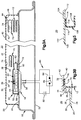
- a vehicle occupant restraint apparatus 10 comprising a first embodiment of the present invention is shown schematically in Fig. 1.
- the apparatus 10 includes an inflatable vehicle occupant restraint 12 and an inflator 14.
- the restraint 12 and the inflator 14 are mounted on a vehicle door 16 in a position adjacent to a seat 18 in the vehicle occupant compartment 20.
- the inflator 14 is actuated.
- the inflator 14 then emits a large volume of inflation fluid which is directed into the restraint 12 to inflate the restraint 12.
- the restraint 12 inflates, it moves outward from the door 16 and into the occupant compartment 20 adjacent to the seat 18.
- the restraint 12 is thus inflated into the occupant compartment 20, it restrains an occupant of the seat 18 to protect the occupant from a forceful impact with the door 16.
- the door 16 has an outer structural panel 22 and an inner structural panel 24.
- the door 16 further includes an inner trim panel 26 between the inner structural panel 24 and the occupant compartment 20.
- the trim panel 26 includes an armrest structure 28.
- the trim panel 26 further has a major section 30 from which the armrest structure 28 projects and a detachable section 32 above the armrest structure 28.
- the major section 30 of the trim panel 26 has a side surface 34 which faces toward the inner structural panel 24, and has an opposite side surface 36 which faces toward the occupant compartment 20.
- the side surface 36 facing toward the occupant compartment 20 partly defines the boundary of the occupant compartment 20 at the door 16.
- An edge surface 38 of the major section 30 of the trim panel 26 defines an opening extending through the major section 30.
- the detachable section 32 of the trim panel 26 also has a side surface 40 facing the inner structural panel 24 and a side surface 42 partly defining the boundary of the occupant compartment 20 at the door 16.
- An edge surface 44 of the detachable section 32 adjoins the edge surface 38 of the major section 30.
- the detachable section 32 further has a peripheral retainer portion 46 which overlies the inner side surface 34 of the major section 30 adjacent to the edge surface 38.
- the detachable section 32 thus extends entirely across, and closes, the opening defined by the edge surface 38.
- the material of the trim panel 26 is deformable sufficiently to enable the retainer portion 46 to move around and past the edge surface 38 for detachment of the detachable section 32 from the major section 30.
- the retainer portion 46 holds the detachable section 32 securely in place, as shown in Fig. 3A, until the inflator 14 is actuated.
- the inflator 14 is part of an inflator module 50 which includes the inflator 14 and a manifold 52.
- the inflator 14 has a short, cylindrical housing 54 with a plurality of gas outlet openings 56.
- the housing 54 contains an ignitable gas generating material which, when ignited, rapidly produces gas for inflating the restraint 12.
- the gas generating material may have any suitable composition known in the art, and is ignited in a known manner upon the passage of electric current between a pair of lead wires 58.
- the preferred embodiments of the invention shown in the drawings use the inflator 14 to provide gas for inflating the restraint 12, other known sources of inflation fluid could be used as alternatives.
- the manifold 52 surrounds, but is spaced from, the gas outlet openings 56 in the housing 54, and has an open end portion 60 defining a gas exit opening 62.
- the manifold 52 thus defines a gas flow space 64 which communicates the gas outlet openings 56 in the housing 54 with the gas exit opening 62 in the manifold 52.
- the module 50 is fixed to the inner structural panel 24 of the door 16 by any suitable fastening structure, such as by a weld 66, with the gas exit opening 52 being located in the space between the inner structural panel 24 and the trim panel 26.
- the restraint 12 has a portion which is defined by an air bag 70.
- the air bag 70 is stored in the space between the inner structural panel 24 and the trim panel 26.
- a first open end 72 of the air bag 70 is received over the open end portion 60 of the manifold 52, and is fixed to the manifold 52 by any suitable means (not shown).
- a second open end 74 of the air bag 70 is fixed to the detachable section 32 of the trim panel 26 by an adhesive 76 (Fig. 3B) or an ultrasonic weld.
- the detachable section 32 of the trim panel 26 thus defines a panel portion of the restraint 12 which is fixed to the air bag 70.
- the inner side surface 40 of the detachable section 32 extends across the second open end 74 of the air bag 70.
- the vehicle occupant restraint apparatus 10 further includes an electrical circuit 80.
- the electrical circuit 80 includes a power source 82, which is preferably the vehicle battery or a capacitor, and a normally open switch 84.
- the switch 84 is part of a sensor 86 which senses the occurrence of a vehicle collision, such as a side impact collision in which the side of the vehicle is impacted by an object, such as another vehicle.
- the sensor 86 closes the switch 84 upon sensing the occurrence of such a side impact collision.
- a sensor is known in the art.
- the electrical circuit 80 directs electric current between the lead wires 58 to actuate the inflator 14 by causing the gas generating material in the inflator 14 to ignite.
- the gas emitted from the inflator 14 flows through the gas flow space 64 to the gas exit opening 62 and into the restraint 12 through the first open end 72 of the air bag 70.
- the gas rushes through the air bag 70 to the detachable section 32 of the trim panel 26, and quickly reaches an elevated pressure within the restraint 12.
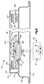
- the air bag 70 inflates from the stored condition of Fig. 3A, and moves into the occupant compartment 20 with the detachable section 32 until the restraint 12 reaches the inflated condition shown in Fig. 4.
- the portion of the major section 30 which is located to right of the detachable section 32, as viewed in Fig. 3A, is sufficiently flexible to be pushed out of the path of movement of the air bag 70 by the air bag 70.
- That portion of the major section 30 thus enables the air bag 70 to move into the space between an adjacent B-pillar and the seat 18.
- the major section 30 could further include other flexible portions about the periphery of the detachable section 32, as needed, depending upon the particular trim panel 26 with which the present invention is used.
- the restraint 12 is thus inflated into the occupant compartment 20 to restrain and protect an occupant of the seat 18 from a forceful impact with the door 16. Since the inner side surface 40 of the detachable section 32 extends across the second open end 74 of the air bag 70, the volume enclosed within the inflated restraint 12 is defined in part by the area of the inner side surface 40 which extends across the second open end 74 of the air bag 70.
- a second embodiment of the present invention includes an alternative trim panel 100 in place of the trim panel 26.
- the material of the trim panel 100 is continuous throughout a major section 102 and a detachable section 104 of the trim panel 100.
- the major section 102 and the detachable section 104 are thus joined to each other as connected parts of the trim panel 100.
- the second embodiment thus includes an inflatable vehicle occupant restraint 106 which includes both an air bag 108 and the detachable section 104 of the trim panel 100.
- the air bag 108 has an open end 110 which is fixed to an inner side surface 112 of the detachable section 104 by an adhesive 114.
- the pressure of the gas directed into the restraint 106 acts outward against the inner side surface 112 when the restraint 106 is being inflated.
- the volume enclosed within the inflated restraint 106 is thus defined in part by the area of the inner side surface 112 which extends across the open end 110 of the air bag 108.
- the trim panel 100 further has an indented surface portion 116 which extends around the entire periphery of the detachable section 104.
- the indented surface portion 116 forms a notch which defines a stress riser in the material of the trim panel 100 that interconnects the detachable section 104 with the major section 102.
- the gas pressure acting outward against the inner side surface 112 reaches a predetermined elevated level, it ruptures the material of the trim panel 100 which comprises the stress riser.
- the detachable section 104 and the air bag 108 are thus released for movement into the occupant compartment 20 by the pressure of the gas directed into the restraint 106.
- a releasable adhesive or other releasable fastening structure could be used with, or in place of, the retainer portion 46 of the detachable section 32 of the trim panel 26 in the first embodiment of the invention.
- a score line, breakable tabs or the like could be used in place of the indented surface portion 116 of the trim panel 100 in the second embodiment. In each case, however, the panel portion of the restraint would be securely held in place on the respective door 16 until the respective inflator 14 is actuated.
- the apparatus 10 includes an inflatable vehicle occupant restraint 200, which is shown partially in Fig. 6.
- the restraint 200 has an air bag portion 202 and a panel portion 204.
- the panel portion 204 of the restraint 200 is substantially the same as either of the alternative panel portions of the restraints described above.
- the air bag portion 202 of the restraint 200 differs from the air bag portions of the restraints described above in that the air bag portion 202 does not have an open end fixed to the panel portion 204. Instead, the air bag portion 202 extends continuously over an inner side surface 206 of the panel portion 204, as shown in Fig. 6.
- a pair of mounting rods 208 with suitable fasteners hold the air bag portion 202 in place against the inner side surface 206.
- the volume enclosed within the inflated restraint 200 is thus defined entirely by the air bag portion 202.
- the apparatus 10 includes an inflatable vehicle occupant restraint 300, which is shown partially in Fig. 7.
- the restraint 300 has an air bag portion 302 and a panel portion 304.
- the structure of the panel portion 304 of the restraint 300 is substantially the same as the structure of any one of the alternative panel portions of the restraints described above.
- the air bag portion 302 of the restraint 300 is similar to the air bag portion 70 of the restraint 12, which is shown in Fig. 3A, in that the air bag portion 302 has an open end 306 which is fixed to the panel portion 304.
- the volume enclosed with the inflated restraint 300 is thus defined in part by the area of an inner side surface 308 of the panel portion 304 which extends across the open end 306 of the air bag portion 302.
- the air bag portion 302 of the restraint 300 differs from the air bag portions of each of the restraints described above in that the air bag portion 302 is divided into distinct tubular sections 312, 314 and 316.
- Each of the tubular sections 312, 314 and 316 communicates with a common air bag portion (not shown) which, in turn, communicates with a source of inflation fluid, such as the inflator 14.
- a source of inflation fluid such as the inflator 14.
- Each of the tubular sections 312, 314 and 316 of the air bag portion 302 adjoins a respective section 318, 320 and 322 of the panel portion 304.
- a plurality of mounting rods 310 with suitable fasteners (not shown) hold the air bag portion 302 in place against the inner side surface 308.
- the mounting rods 310 also separate the tubular sections 312, 314 and 316 of the air bag portion 302 from each other.
- the inflated air bag portion 302 moves the panel portion 304 forcefully away form the inner structural panel 24.
- the pressure of the inflation fluid in each of the tubular sections 312, 314 and 316 of the air bag portion 302 thus applies a force against the respective adjoining section 318, 320 and 322 of the panel portion 304.
- the pressure of the inflation fluid in the restraint 300 can be controlled so that the pressure differs in each of the tubular sections 312, 314 and 316 of the air bag portion 302.
- the respective forces applied by the tubular sections 312, 314 and 316 of the air bag portion 302 to the adjoining sections 318, 320 and 322 of the panel portion 304 will differ accordingly.
- each of the sections 318, 320 and 322 of the panel portion 304 will contact a different part of the occupant's body with a different force as the restraint 300 is inflated.
- This arrangement enables the restraint 300 to contact a relatively sensitive part of the occupant's body with relatively lesser force, and to restrain the relatively sensitive part of the occupant's body with a lower fluid pressure.
- the restraint 300 is able to contact a relatively stronger part of the occupant's body with a relatively greater force and to restrain the relatively stronger part of the occupant's body with a higher fluid pressure.
- the apparatus 10 includes an inflatable vehicle occupant restraint 400, which is shown partially in Fig. 8.
- the restraint 400 has a panel portion 402 which is defined by a detachable section of a door trim panel like the trim panel 26 (Fig. 3A).
- the restraint 400 further has an air bag portion 404.
- the air bag portion 404 of the restraint 400 is similar to the air bag portion 302 of the restraint 300 shown in Fig. 7. However, the air bag portion 404 differs somewhat from the air bag portion 302 in that the air bag portion 404 does not have an open end at the panel portion 402. Instead, the air bag portion 404 of the restraint 400 extends continuously over an inner side surface 408 of the panel portion 402, as shown in Fig. 8.
- a plurality of mounting rods 410 with suitable fasteners hold the air bag portion 404 in place against the inner side surface 408, and also divide the air bag portion 404 into distinct tubular sections 412, 414 and 416 like the tubular sections 312, 314 and 316 of the air bag portion 302 shown in Fig. 7.
- a vehicle occupant restraint apparatus 500 comprising a sixth embodiment of the present invention is shown schematically in Fig. 9.
- the apparatus 500 is associated with a vehicle door 502, and includes a manifold 504 and an inflatable vehicle occupant restraint 506 which differ somewhat from the manifold 50 and the restraint 12 in the apparatus 10 described above.
- Other parts of the apparatus 500 such as an inflator 14 and an electrical circuit 80, are substantially the same as corresponding parts of the apparatus 10, as indicated by the same reference numbers used in Figs. 3A and 9.
- the door 502 has an outer structural panel 510, an inner structural panel 512, and an inner trim panel 514.
- the trim panel 514 has a major section 516 and a detachable section 518.
- the detachable section 518 extends along nearly the entire length of the major section 516 between the opposite ends of the trim panel 514.
- the panel sections 516 and 518 are otherwise substantially the same as the panel sections 30 and 32 shown in Fig. 3A.
- the detachable section 518 is thus detachable from the major section 516 under the influence of inflation fluid pressure directed against an inner side surface 520 of the detachable section 518.
- the manifold 504 surrounds and is spaced from the gas outlet openings 56 in the inflator housing 54.
- a plurality of first gas exit openings 522 extend radially through a cylindrical side wall 524 of the manifold 504.
- a plurality of second gas exit openings 526 extend axially through a circular outer end wall 528 of the manifold 504.
- the manifold 504 is secured to the inner structural panel 512 of the door 502 by a plurality of fasteners 530.
- the fasteners 530 extend through openings in a circular flange 532 at the inner end of the side wall 524.
- the restraint 506 has a panel portion which is defined by the detachable section 518 of the trim panel 514, and further has a portion which is defined by an air bag 540.
- a first open end 542 of the air bag 540 surrounds the inflator 14, and is secured between the inner structural panel 512 and the flange 532 by the fasteners 530.
- a second open end 544 of the air bag 540 is fixed to the detachable section 518 of the trim panel 514 by an adhesive or an ultrasonic weld.
- the gas emitted from the inflator 14 flows into the restraint 506 through the first and second gas exit openings 522 and 526 in the manifold 504.
- the gas rushes through the air bag 540 to the detachable section 518 of the trim panel 514 and quickly reaches an elevated pressure within the restraint 506.
- the pressure of the gas acting outward against the inner side surface 520 causes the detachable section 518 of the trim panel 514 to detach from the major section 516 in the same manner as described above with reference to the corresponding parts of the trim panel 26 shown in Figs. 3A and 3B.
- the air bag 540 inflates and moves into the occupant compartment 20 with the detachable section 518.
- the restraint 506 is thus inflated into the occupant compartment 20 to restrain and protect an occupant of the seat 18 (Fig. 1) from a forceful impact with the door 502.
- the restraint apparatus 500 can have any of the alternative features described above with reference to the restraint apparatus 10.
- tethers are preferably included to control the size and shape of the inflated restraint.
- Such tethers extend across the inside of an inflatable restraint in a known manner.
- the configuration and structure of the detachable panel section, which forms the panel portion of the restraint can be varied for particular applications of the invention.
- a detachable panel section can be covered by a trim layer which gives the panel portion of the restraint an appearance consistent with the trim theme of a particular vehicle.
- Apparatus for restraining an occupant of a vehicle occupant compartment comprising: a vehicle part having a detachable panel section, said detachable panel section of said vehicle part having an outer side surface means for partly defining the occupant compartment; an inflatable vehicle occupant restraint supported on said vehicle part, said restraint being inflatable into an inflated condition in which said restraint extends into the occupant compartment; a source of inflation fluid; and means for directing inflation fluid from said source into said restraint to inflate said restraint; said detachable panel section of said vehicle part comprising a panel portion of said restraint which moves into the occupant compartment upon inflation of said restraint, said panel portion of said restraint having an inner side surface means for contacting said inflation fluid directed into said restraint, said inner side surface means thus partly defining the volume enclosed within said restraint when said restraint is in said inflated condition.
- said restraint has a folded air bag portion which moves into an unfolded, extended condition extending from said vehicle part upon inflation of said restraint, said panel portion of said restraint being fixed to said air bag portion to move from said vehicle part with said air bag portion upon inflation of said restraint.
- said vehicle part is a vehicle door having an inner trim panel, said detachable panel section of said vehicle part being a detachable section of said inner trim panel.
- Apparatus further comprising means for sensing the occurrence of a side impact vehicle collision and means for causing inflation fluid to be emitted from said source in response to a sensed side impact vehicle collision.
- Apparatus for restraining an occupant of a vehicle occupant compartment comprising: a vehicle door having an inner trim panel, said inner trim panel having a detachable section; an inflatable vehicle occupant restraint supported on said door, said restraint having an air bag portion which inflates into a condition extending from said door into the occupant compartment; a source of inflation fluid; and means for directing inflation fluid from said source into said restraint to inflate said restraint; said detachable section of said inner trim panel comprising a panel portion of said restraint, said panel portion of said restraint being fixed to said air bag portion to move from said door into the occupant compartment with said air bag portion upon inflation of said restraint.
- said panel portion of said restraint has an inner side surface means for contacting said inflation fluid directed into said restraint, said inner side surface means thus partly defining the volume enclosed within said restraint when said restraint is inflated.
- Apparatus further comprising means for sensing the occurrence of a side impact vehicle collision and means for causing inflation fluid to be emitted from said source in response to a sensed side impact vehicle collision.
Landscapes
- Engineering & Computer Science (AREA)
- Mechanical Engineering (AREA)
- Air Bags (AREA)
Applications Claiming Priority (2)
| Application Number | Priority Date | Filing Date | Title |
|---|---|---|---|
| US170700 | 1993-12-21 | ||
| US08/170,700 US5439248A (en) | 1993-12-21 | 1993-12-21 | Vehicle occupant restraint apparatus |
Publications (2)
| Publication Number | Publication Date |
|---|---|
| EP0659617A1 true EP0659617A1 (fr) | 1995-06-28 |
| EP0659617B1 EP0659617B1 (fr) | 1999-07-21 |
Family
ID=22620916
Family Applications (1)
| Application Number | Title | Priority Date | Filing Date |
|---|---|---|---|
| EP94120112A Expired - Lifetime EP0659617B1 (fr) | 1993-12-21 | 1994-12-19 | Système de retenue d'un occupant de véhicule |
Country Status (4)
| Country | Link |
|---|---|
| US (1) | US5439248A (fr) |
| EP (1) | EP0659617B1 (fr) |
| JP (1) | JP2750092B2 (fr) |
| DE (1) | DE69419584T2 (fr) |
Cited By (3)
| Publication number | Priority date | Publication date | Assignee | Title |
|---|---|---|---|---|
| DE19604014A1 (de) * | 1996-01-23 | 1997-07-24 | Petri Ag | Vorrichtung zum Schutz von Insassen eines KFZ |
| FR2781442A1 (fr) * | 1998-07-21 | 2000-01-28 | Allibert Ind | Dispositif de protection d'un occupant de vehicule en cas de choc |
| CN105711453A (zh) * | 2014-12-17 | 2016-06-29 | 福特全球技术公司 | 用于车辆车门的扶手的可充气装置 |
Families Citing this family (16)
| Publication number | Priority date | Publication date | Assignee | Title |
|---|---|---|---|---|
| US5540460A (en) * | 1995-04-26 | 1996-07-30 | Trw Vehicle Safety Systems Inc. | Air bag module |
| DE19781051T1 (de) * | 1996-09-30 | 1998-12-10 | Nihon Plast Co Ltd | Airbag-Einrichtung |
| US6152481A (en) * | 1998-08-03 | 2000-11-28 | Delphi Technologies, Inc. | Side restraint assembly |
| US6345837B1 (en) | 1998-11-05 | 2002-02-12 | Chrysler Corporation | Passenger side air bag module |
| US6231072B1 (en) | 1999-10-15 | 2001-05-15 | Delphi Technologies, Inc. | Headliner based supplemental restraint assembly |
| US6422593B1 (en) * | 1999-12-30 | 2002-07-23 | Delphi Technologies, Inc. | Supplemental restraint assembly for an automobile |
| JP4206291B2 (ja) * | 2002-07-08 | 2009-01-07 | 本田技研工業株式会社 | サイドエアバッグ装置 |
| US20060012155A1 (en) * | 2004-07-01 | 2006-01-19 | Ford Global Technologies, Llc | Vehicle side airbag apparatus and seat containing same |
| US20070057491A1 (en) * | 2005-09-09 | 2007-03-15 | Trw Vehicle Safety Systems Inc. | Vehicle occupant protection apparatus located in the door of a vehicle |
| DE102006052190A1 (de) * | 2006-11-02 | 2008-05-08 | Takata-Petri Ag | Airbagmodul für ein Kraftfahrzeug |
| US20080114516A1 (en) * | 2006-11-15 | 2008-05-15 | Jackson David M | Inflatable pusher |
| US20130009430A1 (en) * | 2011-07-07 | 2013-01-10 | Zodiac Aerospace | Energy absorber |
| DE102011109635A1 (de) * | 2011-08-05 | 2013-02-07 | GM Global Technology Operations LLC (n. d. Gesetzen des Staates Delaware) | Kraftfahrzeug mit einer Sicherheitseinrichtung |
| US9272681B1 (en) | 2014-11-25 | 2016-03-01 | Autoliv Asp, Inc. | Knee airbag deployable from a side panel |
| US10525925B2 (en) * | 2017-10-06 | 2020-01-07 | Ford Global Technologies, Llc | Door assembly |
| US11938882B2 (en) | 2021-04-07 | 2024-03-26 | ZF Passive Safety Systems US Inc. | Side airbag packaged in side of seat |
Citations (4)
| Publication number | Priority date | Publication date | Assignee | Title |
|---|---|---|---|---|
| GB1199837A (en) * | 1967-08-16 | 1970-07-22 | Eaton Yale & Towne | Vehicle Safety Device |
| US3767229A (en) * | 1971-12-30 | 1973-10-23 | R Cain | Inflatable dash-panel construction |
| JPH02249740A (ja) * | 1989-03-24 | 1990-10-05 | Mazda Motor Corp | 車体側部のエネルギ吸収構造 |
| DE4217176A1 (de) * | 1992-05-23 | 1993-11-25 | Daimler Benz Ag | Seitenaufprall-Airbag-System |
Family Cites Families (9)
| Publication number | Priority date | Publication date | Assignee | Title |
|---|---|---|---|---|
| CA957404A (en) * | 1970-11-24 | 1974-11-05 | Isao Maeda | Rapidly inflatable impact cushioning device for high-speed travelling vehicle |
| JPS59155257U (ja) * | 1983-04-04 | 1984-10-18 | 日産自動車株式会社 | 自動車の乗員保護装置 |
| US4966388A (en) * | 1989-05-25 | 1990-10-30 | Collision Safety Engineering Inc. | Inflatable structures for side impact crash protection |
| US5072966A (en) * | 1990-03-13 | 1991-12-17 | Mazda Motor Corporation | Energy absorbing structure for vehicle body side portion |
| JP3107383B2 (ja) * | 1990-03-26 | 2000-11-06 | マツダ株式会社 | 車体側部のエネルギ吸収構造 |
| US5242191A (en) * | 1991-01-18 | 1993-09-07 | Trw Vehicle Safety Systems Inc. | Tethered air bag cover |
| JPH0544713U (ja) * | 1991-11-25 | 1993-06-15 | 株式会社東海理化電機製作所 | エアバツグ装置 |
| JPH0687400A (ja) * | 1992-09-04 | 1994-03-29 | Toyota Motor Corp | 衝突エアバッグ用インフレータの取付構造 |
| US5308112A (en) * | 1993-04-21 | 1994-05-03 | General Motors Corporation | Unfurled side impact air bag |
-
1993
- 1993-12-21 US US08/170,700 patent/US5439248A/en not_active Expired - Fee Related
-
1994
- 1994-12-19 EP EP94120112A patent/EP0659617B1/fr not_active Expired - Lifetime
- 1994-12-19 DE DE69419584T patent/DE69419584T2/de not_active Expired - Fee Related
- 1994-12-21 JP JP6318758A patent/JP2750092B2/ja not_active Expired - Lifetime
Patent Citations (4)
| Publication number | Priority date | Publication date | Assignee | Title |
|---|---|---|---|---|
| GB1199837A (en) * | 1967-08-16 | 1970-07-22 | Eaton Yale & Towne | Vehicle Safety Device |
| US3767229A (en) * | 1971-12-30 | 1973-10-23 | R Cain | Inflatable dash-panel construction |
| JPH02249740A (ja) * | 1989-03-24 | 1990-10-05 | Mazda Motor Corp | 車体側部のエネルギ吸収構造 |
| DE4217176A1 (de) * | 1992-05-23 | 1993-11-25 | Daimler Benz Ag | Seitenaufprall-Airbag-System |
Non-Patent Citations (1)
| Title |
|---|
| PATENT ABSTRACTS OF JAPAN vol. 14, no. 575 (M - 1062) 20 December 1990 (1990-12-20) * |
Cited By (5)
| Publication number | Priority date | Publication date | Assignee | Title |
|---|---|---|---|---|
| DE19604014A1 (de) * | 1996-01-23 | 1997-07-24 | Petri Ag | Vorrichtung zum Schutz von Insassen eines KFZ |
| DE19604014C2 (de) * | 1996-01-23 | 1999-07-15 | Petri Ag | Vorrichtung zum Schutz von Insassen eines KFZ |
| US6129375A (en) * | 1996-01-23 | 2000-10-10 | Petri Ag | Device for protecting motor vehicle occupants |
| FR2781442A1 (fr) * | 1998-07-21 | 2000-01-28 | Allibert Ind | Dispositif de protection d'un occupant de vehicule en cas de choc |
| CN105711453A (zh) * | 2014-12-17 | 2016-06-29 | 福特全球技术公司 | 用于车辆车门的扶手的可充气装置 |
Also Published As
| Publication number | Publication date |
|---|---|
| DE69419584D1 (de) | 1999-08-26 |
| DE69419584T2 (de) | 2000-02-24 |
| JPH07195994A (ja) | 1995-08-01 |
| US5439248A (en) | 1995-08-08 |
| JP2750092B2 (ja) | 1998-05-13 |
| EP0659617B1 (fr) | 1999-07-21 |
Similar Documents
| Publication | Publication Date | Title |
|---|---|---|
| US5439248A (en) | Vehicle occupant restraint apparatus | |
| JP2944577B2 (ja) | 車両搭乗者の保護装置 | |
| US6135489A (en) | Tear seam for air bag module cover | |
| EP0818364B1 (fr) | Module de sac gonflable à canal de déploiement | |
| US5749597A (en) | Integral cover-deployment chute for side airbag module | |
| US6942242B2 (en) | Biasing deployment flap and inflatable cushion cover | |
| JP3223245B2 (ja) | 一体化された拘束システムのためのクッションサブモジュール及び空気入れ | |
| JP3188254B2 (ja) | 車の安全装置 | |
| US5628527A (en) | Cover/director for air bag | |
| US5975565A (en) | Vehicle occupant protection apparatus | |
| US6224088B1 (en) | Inflatable occupant protection device extending adjacent a windshield | |
| US5542696A (en) | Seat mounted air bag module | |
| EP0673807A2 (fr) | Procédé et dispositif de gonflage d'un système de retenue gonflable pour occupant de véhicule | |
| US7213837B2 (en) | Airbag module | |
| US5573271A (en) | Side impact air bag inflator | |
| JPH09164894A (ja) | 膨脹可能な拘束モジュール | |
| US5890734A (en) | Integral cover-deployment chute for side airbag module | |
| JP2003034215A (ja) | 乗員保護装置 | |
| WO2000015474A1 (fr) | Airbag a deflecteur | |
| US20050218634A1 (en) | Lower side piller passenger inflatable safety restraint assembly | |
| JP2007511419A (ja) | エアバッグ | |
| US5516144A (en) | Side impact air bag inflator | |
| US5738366A (en) | Chute structure for an inflatable vehicle occupant restraint | |
| CN101460341B (zh) | 用于机动车辆的安全气囊模块 | |
| US6371514B1 (en) | Air bag module mounted in vehicle door |
Legal Events
| Date | Code | Title | Description |
|---|---|---|---|
| PUAI | Public reference made under article 153(3) epc to a published international application that has entered the european phase |
Free format text: ORIGINAL CODE: 0009012 |
|
| AK | Designated contracting states |
Kind code of ref document: A1 Designated state(s): DE FR GB IT SE |
|
| 17P | Request for examination filed |
Effective date: 19950720 |
|
| 17Q | First examination report despatched |
Effective date: 19970123 |
|
| GRAG | Despatch of communication of intention to grant |
Free format text: ORIGINAL CODE: EPIDOS AGRA |
|
| GRAG | Despatch of communication of intention to grant |
Free format text: ORIGINAL CODE: EPIDOS AGRA |
|
| GRAH | Despatch of communication of intention to grant a patent |
Free format text: ORIGINAL CODE: EPIDOS IGRA |
|
| GRAH | Despatch of communication of intention to grant a patent |
Free format text: ORIGINAL CODE: EPIDOS IGRA |
|
| GRAA | (expected) grant |
Free format text: ORIGINAL CODE: 0009210 |
|
| AK | Designated contracting states |
Kind code of ref document: B1 Designated state(s): DE FR GB IT SE |
|
| PG25 | Lapsed in a contracting state [announced via postgrant information from national office to epo] |
Ref country code: SE Free format text: THE PATENT HAS BEEN ANNULLED BY A DECISION OF A NATIONAL AUTHORITY Effective date: 19990721 Ref country code: IT Free format text: LAPSE BECAUSE OF FAILURE TO SUBMIT A TRANSLATION OF THE DESCRIPTION OR TO PAY THE FEE WITHIN THE PRE;WARNING: LAPSES OF ITALIAN PATENTS WITH EFFECTIVE DATE BEFORE 2007 MAY HAVE OCCURRED AT ANY TIME BEFORE 2007. THE CORRECT EFFECTIVE DATE MAY BE DIFFERENT FROM THE ONE RECORDED.SCRIBED TIME-LIMIT Effective date: 19990721 Ref country code: FR Free format text: LAPSE BECAUSE OF FAILURE TO SUBMIT A TRANSLATION OF THE DESCRIPTION OR TO PAY THE FEE WITHIN THE PRESCRIBED TIME-LIMIT Effective date: 19990721 |
|
| REF | Corresponds to: |
Ref document number: 69419584 Country of ref document: DE Date of ref document: 19990826 |
|
| EN | Fr: translation not filed | ||
| PG25 | Lapsed in a contracting state [announced via postgrant information from national office to epo] |
Ref country code: GB Free format text: LAPSE BECAUSE OF NON-PAYMENT OF DUE FEES Effective date: 19991219 |
|
| PLBE | No opposition filed within time limit |
Free format text: ORIGINAL CODE: 0009261 |
|
| STAA | Information on the status of an ep patent application or granted ep patent |
Free format text: STATUS: NO OPPOSITION FILED WITHIN TIME LIMIT |
|
| 26N | No opposition filed | ||
| GBPC | Gb: european patent ceased through non-payment of renewal fee |
Effective date: 19991219 |
|
| PGFP | Annual fee paid to national office [announced via postgrant information from national office to epo] |
Ref country code: DE Payment date: 20061229 Year of fee payment: 13 |
|
| PG25 | Lapsed in a contracting state [announced via postgrant information from national office to epo] |
Ref country code: DE Free format text: LAPSE BECAUSE OF NON-PAYMENT OF DUE FEES Effective date: 20080701 |