EP0659621B1 - Dispositif de limitation de pression - Google Patents
Dispositif de limitation de pression Download PDFInfo
- Publication number
- EP0659621B1 EP0659621B1 EP94117194A EP94117194A EP0659621B1 EP 0659621 B1 EP0659621 B1 EP 0659621B1 EP 94117194 A EP94117194 A EP 94117194A EP 94117194 A EP94117194 A EP 94117194A EP 0659621 B1 EP0659621 B1 EP 0659621B1
- Authority
- EP
- European Patent Office
- Prior art keywords
- pressure
- valve
- limiting device
- inlet
- outlet
- Prior art date
- Legal status (The legal status is an assumption and is not a legal conclusion. Google has not performed a legal analysis and makes no representation as to the accuracy of the status listed.)
- Expired - Lifetime
Links
- 230000009467 reduction Effects 0.000 description 6
- 230000007423 decrease Effects 0.000 description 3
- 238000009434 installation Methods 0.000 description 3
- 230000007547 defect Effects 0.000 description 2
- 239000012528 membrane Substances 0.000 description 2
- 238000007789 sealing Methods 0.000 description 2
- 238000011144 upstream manufacturing Methods 0.000 description 2
- 230000009471 action Effects 0.000 description 1
- 238000004140 cleaning Methods 0.000 description 1
- 230000006835 compression Effects 0.000 description 1
- 238000007906 compression Methods 0.000 description 1
- 238000011109 contamination Methods 0.000 description 1
- 230000008094 contradictory effect Effects 0.000 description 1
- 238000001816 cooling Methods 0.000 description 1
- 230000003247 decreasing effect Effects 0.000 description 1
- 238000001035 drying Methods 0.000 description 1
- 239000012530 fluid Substances 0.000 description 1
- 239000012535 impurity Substances 0.000 description 1
- 230000003993 interaction Effects 0.000 description 1
- 238000004519 manufacturing process Methods 0.000 description 1
- 230000000149 penetrating effect Effects 0.000 description 1
- 230000001681 protective effect Effects 0.000 description 1
- 230000001105 regulatory effect Effects 0.000 description 1
- 238000010792 warming Methods 0.000 description 1
Images

Classifications
-
- B—PERFORMING OPERATIONS; TRANSPORTING
- B60—VEHICLES IN GENERAL
- B60T—VEHICLE BRAKE CONTROL SYSTEMS OR PARTS THEREOF; BRAKE CONTROL SYSTEMS OR PARTS THEREOF, IN GENERAL; ARRANGEMENT OF BRAKING ELEMENTS ON VEHICLES IN GENERAL; PORTABLE DEVICES FOR PREVENTING UNWANTED MOVEMENT OF VEHICLES; VEHICLE MODIFICATIONS TO FACILITATE COOLING OF BRAKES
- B60T11/00—Transmitting braking action from initiating means to ultimate brake actuator without power assistance or drive or where such assistance or drive is irrelevant
- B60T11/10—Transmitting braking action from initiating means to ultimate brake actuator without power assistance or drive or where such assistance or drive is irrelevant transmitting by fluid means, e.g. hydraulic
- B60T11/28—Valves specially adapted therefor
- B60T11/34—Pressure reducing or limiting valves
-
- G—PHYSICS
- G05—CONTROLLING; REGULATING
- G05D—SYSTEMS FOR CONTROLLING OR REGULATING NON-ELECTRIC VARIABLES
- G05D16/00—Control of fluid pressure
- G05D16/04—Control of fluid pressure without auxiliary power
- G05D16/10—Control of fluid pressure without auxiliary power the sensing element being a piston or plunger
Definitions
- the invention relates to a pressure limiting device according to the preamble of claim 1.
- Such a pressure limiting device is from the WABCO Westinghouse publication "Pressure relief valve 475 010 ", October 1975 edition Cross section of the connection between the pressure relief chamber this pressure limiting device and as It is at a pressure relief space serving atmosphere equipped with this pressure limiting device Pressure fluid system possible that a leak between the switching chamber and the pressure reduction chamber to complete Pressure loss in the pressure medium system and thus to the failure of the same leads.
- the invention has for its object such Pressure limiting device with simple means like that to train that they have a lower risk of failure of the pressure medium system guaranteed.
- the invention can be applied to pressure limiting devices any type, for example with a membrane piston member, and in connection with any pressure medium, for example also gaseous.
- a pressure medium for example also gaseous.
- Air is generally the same as the pressure relief space formed by the atmosphere. Otherwise the pressure relief room is a towards the atmosphere essentially overpressure-free collecting or collecting container, which in general also serves as a suction space for the pressure generating system is used.
- the connection between the pressure relief chamber and the pressure relief chamber can through direct opening of the passage from the pressure relief chamber, but also via a pressure medium line.
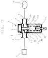
- the inlet (2) is generally designated (5) Pressure limiting device with a pressure generating system (1) connected, while the outlet (7) of the Pressure limiting device with one through its reservoir symbolized consumer group (8) connected is.
- Air serves as the pressure medium.
- the pressure generating system (1) contains in the usual way a pressure generator (compressor or pump) and, if necessary, Pressure accumulators, pressure regulating devices and Pressure medium cooling devices, pressure medium cleaning devices and pressure medium drying devices and is shown schematically only as a block.
- the switching chamber (16) is with the outlet (7) and thus connected to the consumer circuit (8).
- the pressure relief chamber (15) is via a throttle (12) with the as Relief atmosphere serving atmosphere.
- the Atmospheric-side mouth of the throttle (12) is through a elastic disc (13) covered. This prevents a flow out of the Atmosphere in the pressure reduction chamber (15) and thus in the Pressure limiting device (5) and thus prevents access of impurities and moisture.
- an inlet valve (3, 4) provided which consists of a housing-fixed Inlet seat (3) and a movable valve body (4).
- the housing-fixed inlet seat (3) encloses one Breakthrough in one between the inlet (2) and the outlet (7) arranged housing wall.
- the pressure limiting device (5) is a movable piston member (10, 17), which seals the switching chamber (16) separates from the pressure relief chamber (15).
- the piston member (10, 17) has on the switching chamber (16) facing Side a piston surface (9) on which it from the pressure in the switching chamber (16) is applied. This Pressure is the pressure at the outlet (7) and thus the consumer circuit pressure equal.
- piston member (10, 17) shown with sliding Sealing elements are also common to membrane piston members.
- an outlet valve (4, 6) is provided which is by the valve body (4) and one at the valve body end the piston rod (17) arranged outlet seat (6) is formed becomes.
- the piston member is from a pressure relief channel (14) penetrated, on the one hand, inside the outlet seat (6) and on the other hand into the pressure reduction chamber (15) flows.
- the valve body (4) is by an unspecified Closing spring biased towards the inlet seat (3).
- the illustration shows the pressure medium system in the unpressurized Condition, d. H. im free of atmospheric pressure Status.
- the switching spring is in this state (11) relaxed to their greatest possible installation length, whereby the piston member (10, 17) against one not closer designated housing stop is pressed.
- This case stop also defines the greatest possible installation length the switching spring (11) and thus, in addition to its spring rate, that exerted by the switching spring (11) on the switching piston Strength firmly.
- the valve body (4) is in this Position of the piston rod against the force of the Closing spring pressed into a position in which the exhaust valve (4, 6) closed and the inlet valve (3, 4) is fully open.
- a leak on leading to a drop in consumer circuit pressure leads to the value of the limiting pressure.
- a leak can, for example, on a defect of the sealing element the piston member (10, 17), but also on one Breakage of the piston member (10, 17) can be attributed.
- the inlet valve (3, 4) opened with the outlet valve (4, 6) closed.
- the pressure generating system (1) can Limiting pressure in the consumer circuit (8) or at least a lower emergency pressure in the entire pressure medium system maintain.
- the pressure medium loss quantity could be so big that the pressure generating system (1) in a pressure relief device according to the State of the art would not be able to at least one To maintain emergency pressure.
- Such a big one Loss of pressure medium prevents the throttle (12).
- the throttle (12) causes the leak outflowing pressure medium loss in each Case limited to such a value that the pressure generating system (1) maintaining emergency pressure in the pressure medium system.
- the cross section of the Throttle (12) on the delivery capacity of the pressure generating system (1) be coordinated. That means, in principle with decreasing capacity of the pressure generating system (1) the throttle cross section must also decrease. In the event of a pressure generating system (1) with variable delivery capacity, as, for example, in vehicles the variable engine speed are common, this must taken into account when dimensioning the throttle cross-section will.
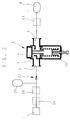
- Fig. 2 shows a two-circuit pressure medium system in which the only in Fig. 1 consumer circuit (8) a first Represents consumer group, while a second consumer group (21) between the inlet (2) of the pressure limiting device (5) and the pressure generating system (1) is arranged.
- the first consumer circuit pressure is p 8
- the second consumer circuit pressure is p 21 .
- p 8 can assume the value of the limiting pressure of the pressure limiting device (5) as the maximum value p 8M
- p 21 can assume the highest delivery pressure of the pressure generating system (1) as the maximum value p 21M .
- Such pressure medium systems in which a second consumer group with a higher pressure level over a Pressure limiting device a first consumer group is connected downstream with a lower pressure level well known.
- a brake system for vehicles is mentioned in the second consumer group with the higher pressure level a service brake circuit and the first consumer circuit an auxiliary brake circuit with the lower pressure level and / or an auxiliary device circuit and / or a trailer supply and control circuit.
- check valve 434 014" It is common in such a pressure medium system first consumer circuit via a check valve to the second consumer group to connect.
- the check valve which, for example, that in WABCO Westinghouse publication "check valve 434 014", August 1973 edition described may correspond then between the inlet of the pressure relief device and the second consumer circuit arranged such that there is a pressure medium flow from the second consumer circuit in the first group of consumers and one Prevents pressure medium flow in the opposite direction.
- a check valve (22) with a predetermined opening pressure p ⁇ is arranged between the inlet (2) of the pressure limiting device (5) and the second consumer circuit (21).
- the opening pressure p ⁇ can be determined, for example, by the fact that the spring, which is usually used only for safe closing, exerts a defined force on the valve body.
- Such a check valve opens when the discharge side is depressurized, i. h if only atmospheric pressure is present on its outflow side, whenever the set opening pressure p ⁇ occurs on its upstream side. If, after opening the check valve, the pressure on its outflow side increases, the check valve maintains a pressure difference between the values of the opening pressure p ⁇ between its upstream side and its outflow side.
- This characteristic of the check valve with a predetermined set opening pressure p ⁇ means in the present case that the check valve (22) is always open to the pressure medium flow from the second consumer circuit (21) towards the first consumer circuit (8) when the pressure difference between the first Consumer circuit pressure p 21 and the pressure at the inlet (2) of the pressure limiting device (5) is equal to the opening pressure p ⁇ , and that the check valve (22) always adjusts this pressure difference.
- the throttle (12) of the pressure generating system (1) enables at least one emergency pressure to be maintained p 8Not in the first consumer group (8).
- this pressure corresponds to a second consumer circuit pressure which is increased by the value of the opening pressure p ⁇ of the check valve (22)
- p 21Not p 8Not + p ⁇ .
- the throttle cross section must in principle also decrease as the delivery capacity of the pressure generating system decreases.
- the selected design of the check valve (22) is also advantageous in this regard. It enables the desired high emergency pressure p 21Not in the second consumer circuit (21) with a throttle cross-section that is larger than when using a conventional check valve, is easier to manufacture and is also less sensitive to contamination.
- the basic design of the pressure medium system according to FIG. 2 described so far can be arranged by arranging an overflow valve between the pressure generating system (1) and the second consumer circuit (21) and an overflow valve between the outlet (7) of the pressure limiting device (5) and the second consumer circuit (8). train.
- Such overflow valves are indicated in FIG. 2 as blocks (20; 23) shown in broken lines.
- Such overflow valves serve to ensure the filling order of the consumer groups and, in the event of a defect in one of the consumer groups (8 or 21), to protect the other consumer group.
- the opening pressure of the protective valve (23) assigned to the first consumer circuit (8) must be below the limiting pressure of the pressure limiting device (5).
- the opening pressure of the overflow valve (20) assigned to the second consumer circuit (21) can, but need not, be higher than the opening pressure of the overflow valve (23). It is expedient that the opening pressure of the overflow valve (20) of the second consumer circuit (21) is greater than the opening pressure of the overflow valve (23) of the first consumer circuit (8) by the value of the opening pressure p ⁇ of the check valve (22).
- the exemplary embodiment also shows in dashed lines a pressure limiting device (24) of any type between the pressure generating system (1) and the second consumer circuit (8).
- the limiting pressure of this pressure limiting device (24) must be set to the maximum value p 21M of the second consumer circuit pressure (21), so that the difference in the limiting pressures of the two pressure limiting devices (24 and 5) corresponds to the opening pressure p ⁇ of the check valve (22).
- the pressure generating system (1) can be designed for an even higher pressure level, for example to increase the working capacity of the pressure medium system.
- Fig. 3 shows a three-circuit pressure medium system in which between the inlet (2) of the pressure limiting device (5) and the pressure generating system (1) parallel to that second consumer circuit (21) further second Consumer group (31) is arranged. Between this Consumer circuit (31) and the inlet (2) of the pressure limiting device (5) a check valve (32) is arranged, which has the same predetermined opening pressure as the check valve (22). Both check valves therefore, as indicated in the drawing, using a common spring to form an assembly unite.
- a vehicle braking system with a two-circuit system is an example Service brake system mentioned, each in a service brake circuit from one of the second consumer groups (21 and 31) of the embodiment is shown. Also between the other second service brake circuit (31) and the pressure generating system (1) can be Training of the exemplary embodiment, as indicated by dashed lines, arrange an overflow valve (30).
- Another second group of consumers for whom what has just been said mitgilt can be parallel to those shown order second consumer groups.
- the pressure medium system can also be one or more train further first consumer groups for which what was said about the first consumer group (8) accordingly also applies. Another is shown by dashed lines first consumer group (34) shown. This one too can, like the first consumer group (8), with a dashed line indicated overflow valve (33) trained will.
- Overflow valves can be used in the WABCO Westinghouse publication "Überströmventil 434 100", edition August 1973 types are used, the conditions of the individual case being the exact Determine the type.
- Those mentioned in the exemplary embodiments Overflow valves form together with the check valve or the check valves each Protection system for which, for example, the designs in US 4817502 apply accordingly. From this publication it is also known that such protection systems in one unit each to a multi-circuit protection valve can be summarized.
Landscapes
- Engineering & Computer Science (AREA)
- Physics & Mathematics (AREA)
- Transportation (AREA)
- Mechanical Engineering (AREA)
- Fluid Mechanics (AREA)
- General Physics & Mathematics (AREA)
- Automation & Control Theory (AREA)
- Safety Valves (AREA)
- Control Of Fluid Pressure (AREA)
- Fluid-Pressure Circuits (AREA)
- Braking Systems And Boosters (AREA)
Claims (2)
- Dispositif de limitation de pression, comprenant :a) une entrée (2) reliée à une installation de production de pression (1),b) une sortie (7) reliée à au moins un circuit utilisateur (8 ; 34),c) une valve d'entrée (3, 4) qui relie l'entrée (2) à la sortie (7),d) une valve de sortie (4, 6) qui relie la sortie (7) à une chambre de réduction de pression (15) reliée à un espace de décharge de pression,e) un ressort de commutation (11),f) un organe de piston (10, 17) mobile, qui sépare de façon étanche par rapport à la chambre de réduction de pression (15) une chambre de commutation (16) reliée à la sortie (7), et qui assure l'ouverture et la fermeture des valves précitées (3, 4 et 4, 6), et oùh) l'organe formant piston (10, 17) est sollicité en direction de l'ouverture de la valve de sortie (4, 6) et de la fermeture de la valve d'entrée (3, 4) par la pression dans la chambre de commutation (16), et en direction de l'ouverture de la valve d'entrée (3, 4) et de la fermeture de la valve de sortie (4, 6) par le ressort de commutation (11),
caractérisé en ce quei) dans la jonction entre la chambre de réduction de pression (15) et l'espace de décharge de pression est agencé un étranglement (12) dont les dimensions sont choisies de manière que, même lors d'un défaut d'étanchéité prononcé entre la chambre de commutation (16) et la chambre de réduction de pression (15) de l'installation de production de pression (1), il permet le maintien d'eau moins une pression de secours dans l'installation à fluide sous pression, même dans le cas d'une faible capacité de refoulement. - Dispositif de limitation de pression selon la revendication 1, dont l'entrée (2) est reliée à l'installation de production de pression (1) via au moins un second circuit utilisateur (21 ; 31) avec un niveau de pression qui dépasse le niveau de pression du circuit utilisateur (8 ; 34) relié à la sortie (7) du dispositif de limitation de pression (5),
caractérisé en ce que
entre l'entrée (2) du dispositif de limitation de pression (5) et le second circuit utilisateur (21 ; 31) est agencé un clapet anti-retour (22, ; 32) avec une pression d'ouverture prédéterminée, dont la pression d'ouverture est égale à la différence de pression entre les niveaux de pression des circuits utilisateurs (22 ; 32).
Applications Claiming Priority (2)
| Application Number | Priority Date | Filing Date | Title |
|---|---|---|---|
| DE4344416 | 1993-12-24 | ||
| DE4344416A DE4344416A1 (de) | 1993-12-24 | 1993-12-24 | Druckbegrenzungseinrichtung |
Publications (2)
| Publication Number | Publication Date |
|---|---|
| EP0659621A1 EP0659621A1 (fr) | 1995-06-28 |
| EP0659621B1 true EP0659621B1 (fr) | 1998-04-01 |
Family
ID=6506170
Family Applications (1)
| Application Number | Title | Priority Date | Filing Date |
|---|---|---|---|
| EP94117194A Expired - Lifetime EP0659621B1 (fr) | 1993-12-24 | 1994-10-31 | Dispositif de limitation de pression |
Country Status (4)
| Country | Link |
|---|---|
| EP (1) | EP0659621B1 (fr) |
| JP (1) | JP3328793B2 (fr) |
| DE (2) | DE4344416A1 (fr) |
| RU (1) | RU2137175C1 (fr) |
Families Citing this family (15)
| Publication number | Priority date | Publication date | Assignee | Title |
|---|---|---|---|---|
| RU2171412C2 (ru) * | 1999-09-16 | 2001-07-27 | Общество с ограниченной ответственностью "Посейдон МВК" | Редукционный клапан |
| DE10222903A1 (de) * | 2002-05-23 | 2003-12-11 | Knorr Bremse Systeme | Druckbegrenzungseinrichtung und Verfahren zum Entlasten einer Druckbegrenzungseinrichtung |
| DE102004023255B3 (de) * | 2004-05-11 | 2005-12-01 | Knorr-Bremse Systeme für Schienenfahrzeuge GmbH | Druckminderventil |
| DE102008053994B4 (de) | 2008-10-30 | 2015-10-29 | Knorr-Bremse Systeme für Nutzfahrzeuge GmbH | Druckluftbegrenzungseinrichtung |
| DE102008063819A1 (de) * | 2008-12-19 | 2010-07-01 | Wabco Gmbh | Kombiniertes Druckbegrenzungs- und Überströmerventil |
| DE102010008063A1 (de) | 2010-02-16 | 2011-08-18 | WABCO GmbH, 30453 | Druckluftkompressor und Verfahren zum Betrieb eines Druckluftkompressors |
| RU2439412C1 (ru) * | 2010-04-12 | 2012-01-10 | Государственное образовательное учреждение высшего профессионального образования "Тульский государственный университет" (ТулГУ) | Пускоотсечной электропневмоклапан постоянного низкого давления |
| DE102012007813A1 (de) | 2012-04-18 | 2013-10-24 | Wabco Gmbh | Pneumatisches Ventil |
| CN102837734B (zh) * | 2012-09-20 | 2014-08-06 | 荆州恒隆汽车零部件制造有限公司 | 一种可改善转向器液压噪音异响的液体稳流器 |
| DE102015118963A1 (de) | 2015-11-05 | 2017-05-11 | Knorr-Bremse Systeme für Nutzfahrzeuge GmbH | Druckbegrenzungsventil |
| DE102015118962A1 (de) | 2015-11-05 | 2017-05-11 | Knorr-Bremse Systeme für Nutzfahrzeuge GmbH | Druckbegrenzungsventil |
| DE102016117607A1 (de) | 2016-09-19 | 2018-03-22 | Knorr-Bremse Systeme für Nutzfahrzeuge GmbH | Druckregelventil für ein Luftaufbereitungssystem eines Nutzfahrzeugs |
| EP3502824A1 (fr) * | 2017-12-19 | 2019-06-26 | WABCO Europe BVBA | Soupape de limitation de pression, système d'alimentation en air comprimé |
| DE102018108976A1 (de) | 2018-04-16 | 2019-10-17 | Wabco Europe Bvba | Druckbegrenzungsventil |
| CN113090796B (zh) * | 2021-05-21 | 2025-06-17 | 河南安燃智控科技有限公司 | 多功能燃气机械自闭阀 |
Family Cites Families (16)
| Publication number | Priority date | Publication date | Assignee | Title |
|---|---|---|---|---|
| US3559688A (en) * | 1965-06-04 | 1971-02-02 | Mack Trucks | Fluid pressure regulating valve |
| ES445020A1 (es) * | 1976-02-10 | 1977-06-01 | Bendiberica Sa | Perfeccionamientos en valvulas de limitacion de presion. |
| DE2619769C2 (de) * | 1976-05-05 | 1986-02-13 | Robert Bosch Gmbh, 7000 Stuttgart | Druckbegrenzer |
| DE2922837A1 (de) * | 1979-06-06 | 1980-12-18 | Bosch Gmbh Robert | Druckbegrenzungsventil |
| DE3001368A1 (de) * | 1980-01-16 | 1981-08-27 | Alfred Teves Gmbh, 6000 Frankfurt | Leckage-einrichtung |
| DE3026283C2 (de) * | 1980-07-11 | 1982-06-03 | Knorr-Bremse GmbH, 8000 München | Druckbegrenzer |
| IT1136996B (it) * | 1981-05-14 | 1986-09-03 | Magneti Marelli Spa | Riduttore della pressione pneumatica negli elementi frenanti dell'asse anteriore di veicoli |
| DE3311816C1 (de) * | 1983-03-31 | 1984-07-05 | Graubremse Gmbh, 6900 Heidelberg | Druckbegrenzungsventil fuer Druckluftbremsanlagen von Kraftfahrzeugen |
| DE3434884C2 (de) * | 1984-09-22 | 2000-03-16 | Wabco Gmbh | Schutzsystem für eine Kraftfahrzeug-Druckluftanlage |
| DE3513452A1 (de) * | 1985-04-15 | 1986-10-16 | Mannesmann Rexroth GmbH, 8770 Lohr | Hydrauliksystem fuer die versorgung einer hydrostatischen lenkung |
| DE3633660A1 (de) * | 1986-10-03 | 1988-04-14 | Bodenseewerk Perkin Elmer Co | Sicherheitsvorrichtung bei membran-gasdruckreglern |
| DE4001306A1 (de) * | 1990-01-18 | 1991-07-25 | Bosch Gmbh Robert | Hydraulikanlage fuer ein kraftfahrzeug |
| DE4012576A1 (de) * | 1990-04-20 | 1991-10-24 | Bosch Gmbh Robert | Druckbegrenzungsventil mit einem sicherheitsventil |
| CH683803A5 (fr) * | 1990-05-18 | 1994-05-13 | Hobac S A | Vanne régulatrice automatique. |
| DE4027455A1 (de) * | 1990-08-30 | 1992-03-12 | Bosch Gmbh Robert | Druckregelventil |
| DE4114977A1 (de) * | 1991-05-08 | 1992-11-12 | Bosch Gmbh Robert | Druckbegrenzungsventil |
-
1993
- 1993-12-24 DE DE4344416A patent/DE4344416A1/de not_active Withdrawn
-
1994
- 1994-10-31 DE DE59405579T patent/DE59405579D1/de not_active Expired - Lifetime
- 1994-10-31 EP EP94117194A patent/EP0659621B1/fr not_active Expired - Lifetime
- 1994-12-09 JP JP33517494A patent/JP3328793B2/ja not_active Expired - Fee Related
- 1994-12-23 RU RU94045805A patent/RU2137175C1/ru active
Also Published As
| Publication number | Publication date |
|---|---|
| EP0659621A1 (fr) | 1995-06-28 |
| RU94045805A (ru) | 1996-10-20 |
| DE4344416A1 (de) | 1995-06-29 |
| JP3328793B2 (ja) | 2002-09-30 |
| JPH07210255A (ja) | 1995-08-11 |
| RU2137175C1 (ru) | 1999-09-10 |
| DE59405579D1 (de) | 1998-05-07 |
Similar Documents
| Publication | Publication Date | Title |
|---|---|---|
| EP0659621B1 (fr) | Dispositif de limitation de pression | |
| DE102004052375B4 (de) | Federspeicherbremszylinder und Verfahren zu seinem Betrieb | |
| EP3371018A1 (fr) | Soupape de limitation de pression | |
| EP2675672B1 (fr) | Soupape de protection multicircuits pour dispositif d'alimentation en air comprimé d'un véhicule et procédé de fonctionnement d'une soupape de protection multicircuit | |
| DE2206975C3 (de) | Schutzvorrichtung für Mehrkreisdruckluftleitungssysteme, insbesondere für Mehrkreisbremsanlage!! von Kraftfahrzeugen | |
| EP1519866B1 (fr) | Dispositif de ventilation d'un cylindre de freinage | |
| EP1851098B1 (fr) | Cylindre de frein a accumulateur a ressort et de service combine avec dispositif de respiration | |
| DE1131535B (de) | Steuerventil fuer Zweileitungsdruckmittelbremsanlagen in Fahrzeuganhaengern | |
| DE2615893A1 (de) | Anhaenger-steuerventil | |
| DE19710814C1 (de) | Druckluftaufbereitungseinrichtung für Druckluftbeschaffungsanlagen auf Kraftfahrzeugen | |
| DE2310383A1 (de) | Druck-rueckhalteventil | |
| EP0717201B1 (fr) | Système de protection dans une installation sous pression | |
| DE3213236A1 (de) | Einrichtung mit einem lufttrockner fuer druckluftanlagen | |
| DE19626956B4 (de) | Gastrockner mit einer Auslaßkammer | |
| DE10238670B4 (de) | Mehrkreisschutzventil für Druckluftbremsanlagen von Nutzfahrzeugen | |
| DE1923543B2 (de) | Unterbrecherventil für pneumatische Anlagen mit mehreren Verbrauchern | |
| EP0937624B1 (fr) | Aménagement avec un dispositif de valve | |
| DE4041710A1 (de) | Druckluftanlage mit einem hochdruckteil und einem niederdruckteil | |
| DE4414596B4 (de) | Druckmittelanlage mit wenigstens zwei Verbraucherkreisen | |
| WO2004040120A1 (fr) | Dispositif pour reduire la quantite de liquide qui est aspiree par une pompe d'alimentation | |
| DE19545640B4 (de) | Steuerventileinrichtung | |
| DE3132745C2 (fr) | ||
| AT373675B (de) | Druckbegrenzungsventil fuer hydraulikanlagen | |
| DE2856754A1 (de) | Sicherheitsvorrichtung fuer einen hydraulikkreis | |
| DE1500074C3 (de) | Hdraulfscher Druckregler |
Legal Events
| Date | Code | Title | Description |
|---|---|---|---|
| PUAI | Public reference made under article 153(3) epc to a published international application that has entered the european phase |
Free format text: ORIGINAL CODE: 0009012 |
|
| 17P | Request for examination filed |
Effective date: 19950418 |
|
| AK | Designated contracting states |
Kind code of ref document: A1 Designated state(s): DE FR GB IT SE |
|
| 17Q | First examination report despatched |
Effective date: 19960712 |
|
| GRAG | Despatch of communication of intention to grant |
Free format text: ORIGINAL CODE: EPIDOS AGRA |
|
| GRAG | Despatch of communication of intention to grant |
Free format text: ORIGINAL CODE: EPIDOS AGRA |
|
| GRAH | Despatch of communication of intention to grant a patent |
Free format text: ORIGINAL CODE: EPIDOS IGRA |
|
| GRAH | Despatch of communication of intention to grant a patent |
Free format text: ORIGINAL CODE: EPIDOS IGRA |
|
| GRAA | (expected) grant |
Free format text: ORIGINAL CODE: 0009210 |
|
| AK | Designated contracting states |
Kind code of ref document: B1 Designated state(s): DE FR GB IT SE |
|
| ITF | It: translation for a ep patent filed | ||
| REF | Corresponds to: |
Ref document number: 59405579 Country of ref document: DE Date of ref document: 19980507 |
|
| ET | Fr: translation filed | ||
| GBT | Gb: translation of ep patent filed (gb section 77(6)(a)/1977) |
Effective date: 19980701 |
|
| PLBE | No opposition filed within time limit |
Free format text: ORIGINAL CODE: 0009261 |
|
| STAA | Information on the status of an ep patent application or granted ep patent |
Free format text: STATUS: NO OPPOSITION FILED WITHIN TIME LIMIT |
|
| 26N | No opposition filed | ||
| PGFP | Annual fee paid to national office [announced via postgrant information from national office to epo] |
Ref country code: GB Payment date: 20011031 Year of fee payment: 8 |
|
| REG | Reference to a national code |
Ref country code: GB Ref legal event code: IF02 |
|
| PGFP | Annual fee paid to national office [announced via postgrant information from national office to epo] |
Ref country code: SE Payment date: 20021015 Year of fee payment: 9 |
|
| PGFP | Annual fee paid to national office [announced via postgrant information from national office to epo] |
Ref country code: FR Payment date: 20021018 Year of fee payment: 9 |
|
| PG25 | Lapsed in a contracting state [announced via postgrant information from national office to epo] |
Ref country code: GB Free format text: LAPSE BECAUSE OF NON-PAYMENT OF DUE FEES Effective date: 20021031 |
|
| GBPC | Gb: european patent ceased through non-payment of renewal fee | ||
| PG25 | Lapsed in a contracting state [announced via postgrant information from national office to epo] |
Ref country code: FR Free format text: LAPSE BECAUSE OF NON-PAYMENT OF DUE FEES Effective date: 20030630 |
|
| REG | Reference to a national code |
Ref country code: FR Ref legal event code: ST |
|
| PG25 | Lapsed in a contracting state [announced via postgrant information from national office to epo] |
Ref country code: SE Free format text: LAPSE BECAUSE OF NON-PAYMENT OF DUE FEES Effective date: 20031101 |
|
| EUG | Se: european patent has lapsed | ||
| PG25 | Lapsed in a contracting state [announced via postgrant information from national office to epo] |
Ref country code: IT Free format text: LAPSE BECAUSE OF NON-PAYMENT OF DUE FEES;WARNING: LAPSES OF ITALIAN PATENTS WITH EFFECTIVE DATE BEFORE 2007 MAY HAVE OCCURRED AT ANY TIME BEFORE 2007. THE CORRECT EFFECTIVE DATE MAY BE DIFFERENT FROM THE ONE RECORDED. Effective date: 20051031 |
|
| PGFP | Annual fee paid to national office [announced via postgrant information from national office to epo] |
Ref country code: DE Payment date: 20131031 Year of fee payment: 20 |
|
| REG | Reference to a national code |
Ref country code: DE Ref legal event code: R071 Ref document number: 59405579 Country of ref document: DE |