EP0659631B1 - Vorderes Tragwerk für ein Kraftfahrzeug und Kraftfahrzeug mit diesem Tragwerk - Google Patents
Vorderes Tragwerk für ein Kraftfahrzeug und Kraftfahrzeug mit diesem Tragwerk Download PDFInfo
- Publication number
- EP0659631B1 EP0659631B1 EP19940402961 EP94402961A EP0659631B1 EP 0659631 B1 EP0659631 B1 EP 0659631B1 EP 19940402961 EP19940402961 EP 19940402961 EP 94402961 A EP94402961 A EP 94402961A EP 0659631 B1 EP0659631 B1 EP 0659631B1
- Authority
- EP
- European Patent Office
- Prior art keywords
- main
- vehicle
- front structure
- structure according
- longitudinal members
- Prior art date
- Legal status (The legal status is an assumption and is not a legal conclusion. Google has not performed a legal analysis and makes no representation as to the accuracy of the status listed.)
- Expired - Lifetime
Links
- 239000000725 suspension Substances 0.000 claims description 16
- 230000035939 shock Effects 0.000 claims description 9
- 230000005540 biological transmission Effects 0.000 claims description 6
- 239000000463 material Substances 0.000 claims description 3
- 238000003466 welding Methods 0.000 claims description 3
- 238000013016 damping Methods 0.000 claims 1
- 238000010521 absorption reaction Methods 0.000 description 4
- 238000005452 bending Methods 0.000 description 1
- 239000000470 constituent Substances 0.000 description 1
- 238000010494 dissociation reaction Methods 0.000 description 1
- 230000005593 dissociations Effects 0.000 description 1
- 230000005484 gravity Effects 0.000 description 1
- 238000004519 manufacturing process Methods 0.000 description 1
- 230000004048 modification Effects 0.000 description 1
- 238000012986 modification Methods 0.000 description 1
Images


Classifications
-
- B—PERFORMING OPERATIONS; TRANSPORTING
- B62—LAND VEHICLES FOR TRAVELLING OTHERWISE THAN ON RAILS
- B62D—MOTOR VEHICLES; TRAILERS
- B62D21/00—Understructures, i.e. chassis frame on which a vehicle body may be mounted
- B62D21/15—Understructures, i.e. chassis frame on which a vehicle body may be mounted having impact absorbing means, e.g. a frame designed to permanently or temporarily change shape or dimension upon impact with another body
- B62D21/152—Front or rear frames
Definitions
- the present invention relates to a front structure of a front-wheel drive motor vehicle, in particular of an electric motor vehicle, and to a vehicle equipped with this structure.
- a front structure of a motor vehicle comprising a stretcher consisting of two beams symmetrical with respect to the median plane of the vehicle and connected by a cross member, the front ends of the beams being curved and raised to support the front elements of the vehicle and the fasteners. of the engine located laterally and at its center of gravity.
- Such a structure has many drawbacks, and in particular during a front impact, the side members tend to bend and damage the passenger compartment of the vehicle.
- the present invention therefore aims to eliminate the aforementioned drawbacks and to provide a front structure of a motor vehicle which has a high shock absorption capacity, a simplified structure and which makes it possible to preserve the integrity of the passenger compartment of the vehicle. , especially in the event of a frontal impact.
- the subject of the present invention is a front structure of a motor vehicle, in particular an electric motor, comprising a main stretcher secured to the passenger compartment of the vehicle and consisting of two main beams symmetrical with respect to the median plane of the vehicle and connected by a main cross member, the vehicle comprising a transmission and a front suspension constituted in particular by a suspension arm, characterized in that said spars main are straight, pass under the passenger compartment of the vehicle and support at their front end side engine attachments as well as internal articulations of each suspension arm.
- the invention therefore provides a streamlined front structure of manufacture simpler than currently known structures, because it eliminates the bending of the front ends of the side members.
- the front structure comprises an upper stretcher secured to the main stretcher and consisting of two upper beams, the front ends of which are connected by a front crosspiece which only supports the radiator, the projectors and / or the vehicle bumper.
- This characteristic makes it possible to dissociate the structural elements integral with the passenger compartment of the vehicle, namely the main stretcher, from the other structural elements liable to be subjected to a frontal impact, namely the upper stretcher.
- the dissociation of the front structure into an upper stretcher and a main stretcher makes it possible both to improve the shock absorption capacity of the front structure thanks to the upper stretcher and to preserve the integrity of the vehicle interior which, he is positively connected to the main stretcher.
- each upper beam is fixed by its rear end to the main cross member, and a vertical tie connects the front end of each main beam to the corresponding upper beam.
- the internal articulations of the suspension arms are mounted at the front on the above-mentioned vertical tie rod and at the rear on a bracket fixed to each main spar.
- the main crossmember is optionally curved at its lateral ends and has a concavity oriented towards the rear of the vehicle, said lateral ends being connected to the door legs of the vehicle and the central part of said main crossmember being fixed, preferably by welding, to the main beams at the aforementioned brackets which support the internal and rear articulations of the suspension arms.
- the spacing of the two main beams can be substantially equal to the spacing of the engine fasteners so that the latter are fixed to the front end of the main beams which is U-shaped.
- the main beams are advantageously bevelled at their upper front end to allow the transmission to pass, in particular in the event of a frontal impact.
- the upper beams are connected to shock absorbing means by means of support gantries.
- the spacing of the main beams is less than that of the upper beams so as to optionally allow the retraction of the upper beams, in particular in the event of a front impact.
- the upper stretcher can constitute a shock absorbing structure, formed for example of folds, elastic means and / or of a light deformable material.
- the present invention also relates to a motor vehicle equipped with a front structure according to any one of the characteristics mentioned above.
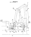
- FIG. 1 is a schematic view in side elevation and in section of the front structure of the invention, along the line I-I of FIG. 2.
- FIG. 2 is a diagrammatic half-view from above, in section and partially cut away of the front structure of FIG. 1, along the line II-II of FIG. 3.
- Figure 3 is a schematic half-view in front elevation and in section of the front structure of Figure 1, along line III-III thereof.
- the front structure of the invention is mounted on a motor vehicle 1 which comprises a cover 2, a front bumper 3 and a front wing 4.
- the vehicle 1 also comprises a motor 5 which is connected, by means of a constant velocity connection with cardan joints 6 forming the front transmission of the vehicle, to bearings (not shown) of the wheel support 7 (see FIGS. 2 and 3).
- a front suspension including a triangle or lower suspension arm 8 and an upper telescopic leg 9 of shock absorption, each front suspension being articulated with respect to a wheel 7 which rests on the floor 10.
- Each suspension arm 8 is articulated at its external end 8a on the lower end of the telescopic leg 9 around a ball joint 11, and at its internal front ends 8b and rear 8c on a tubular main spar 12 around an axis 11a.
- the front internal 8b and rear 8c ends of the suspension arms 8 are articulated on the main beams 12 respectively by means of vertical tie rods 13 and brackets 14 which are fixed to the external lateral walls of the main beams 12.
- the two main beams 12 are symmetrical with respect to the median plane of the vehicle 1, connected by a main cross member 15 and constitute the main stretcher of the front structure of the invention.
- the main crosspiece 15 is preferably made in one piece to ensure better impact resistance. It is hollow, curved, has a trapezoidal cross section 15a and has a concavity oriented towards the rear of the vehicle 1.
- the central part of the cross-member 15 is fixed, for example by bolts or preferably by welding, on the upper face of the main tubular beams 12.
- the lateral ends 15b of the main crosspiece 15 are connected to side members forming door legs 17 of the vehicle 1.
- Tubular upper beams 18, connected at their front ends by a front cross member 19, constitute an upper stretcher secured to the main stretcher.
- the front crossmember 19 is intended to support only the radiator, the headlights (represented in FIG. 1 by a block 20) and / or the front bumper 3 of the vehicle 1.
- Each upper tubular beam 18 is fixed by its rear end to the central part of the main cross member 15, said rear end preferably being supported on the latter.
- a vertical tie 13 connects the front end 12a of each main beam 12 to the corresponding upper beam 18.
- the main cross member 15 serves as a support for the upper stretcher which may be different in terms of its section, its inertia and its constituent material, of the main stretcher, so as to increase the shock absorption capacity of the upper stretcher.
- the main and upper stretchers can optionally be connected by additional sheets, to stiffen and increase the inertia of the assembly.
- each main beam 12 is bevelled on its upper face to allow the passage of the transmission 6, in particular during a front impact.
- the engine 5 is fixed to the main beams 12 by means of supports 21 and by fasteners 22 which project laterally from the engine 5.
- Each support 21 is fixed to the front end 12a of the main spar 12 by means of bolts or screws 23 and has a cylindrical part in which there is an elastic articulation fitted 24 connected to a fastener 22 of the motor 5 by a screw 24a.
- One of the bolts 23 can also be used to fix the vertical tie rod 13 to the main beam 12.
- the spacing of the main beams 12 is substantially equal to the spacing of the fasteners 22 of the motor 5.
- the supports 21 can be arranged laterally with respect to the main beams 12.
Landscapes
- Engineering & Computer Science (AREA)
- Chemical & Material Sciences (AREA)
- Combustion & Propulsion (AREA)
- Transportation (AREA)
- Mechanical Engineering (AREA)
- Body Structure For Vehicles (AREA)
Claims (12)
- Vorderaufbau eines Kraftfahrzeuges insbesondere mit elektrischem Motor, mit einem mit dem Fahrgastraum des Fahrzeuges fest verbundenen Hauptbalken, der aus zwei in bezug auf die Mittelebene des Fahrzeuges (1) symmetrischen und durch eine Hauptquerstrebe (15) verbundenen Hauptlängsträgern (12) besteht, wobei das Fahrzeug eine Kraftübertragung (6) und eine insbesondere aus einem Aufhängungsarm (8) bestehende Vorderaufhängung aufweist, dadurch gekennzeichnet, daß die besagten Hauptlängsträger (12) geradlinig sind, unter dem Fahrgastraum (16) des Fahrzeuges (1) verlaufen und an ihrem Vorderende (12a) Seitenhalterungsanschlüße (22) des Motors (5), sowie innere Gelenke (8b) jedes Aufhängungsarmes (8) tragen.
- Vorderaufbau gemäß Anspruch 1, dadurch gekennzeichnet, daß er einen oberen mit dem Hauptbalken (12, 15) fest verbundenen oberen Balken (18, 19) aufweist, der aus zwei oberen Längsträgern (18) besteht, deren Vorderenden durch eine Vorderquerstrebe (19), die nur den Kühler, die Scheinwerfer (20) und/oder die Stoßstange (3) des Fahrzeuges (1) trägt, verbunden sind.
- Vorderaufbau gemäß Anspruch 2, dadurch gekennzeichnet, daß jeder obere Längsträger (18) mit seinem hinteren Ende an der Hauptquerstrebe (15) befestigt ist und daß eine senkrechte Strebe (13) das Vorderende (12a) jedes Hauptlängsträgers (12) mit dem entsprechenden oberen Längsträger (18) verbindet.
- Vorderaufbau gemäß Anspruch 3, dadurch gekennzeichnet, daß die Aufhängungsarme (8) mit ihrem vorderen Innenende (8b) an den senkrechten Streben (13) angelenkt sind.
- Vorderaufbau gemäß Anspruch 3 oder 4, dadurch gekennzeichnet, daß die Aufhängungsarme (8) mit ihrem hinteren Innenende (8c) an einem an jedem Hauptlängsträger (12) befestigten Winkel (14) angelenkt sind.
- Vorderaufbau gemäß Anspruch 5, dadurch gekennzeichnet, daß die Hauptquerstrebe (15) an ihren Seitenenden (15b) gebogen ist und eine dem hinteren Teil des Fahrzeuges (1) zugewandte Konkavität aufweist, wobei die besagten Seitenenden (15b) mit den Türfüßen (17) des Fahrzeuges verbunden sind und der Zentralabschnitt der besagten Hauptquerstrebe (15) an den Hauptlängsträgern (12) im Bereich der Winkel (14) vorzugsweise durch Schweißung befestigt ist.
- Vorderaufbau gemäß irgendwelchem der vorangehenden Ansprüche, dadurch gekennzeichnet, daß der Abstand zwischen den beiden Hauptlängsträgern (12) etwa dem Abstand der Halterungsanschlüße (22) des Motors (5) etwa gleich ist, so daß die letzteren an dem Vorderende (12a) der Hauptlängsträger (12), das ein U-förmiges Profil aufweist, befestigt sind.
- Vorderaufbau nach irgendeinem der vorangehenden Ansprüche, dadurch gekennzeichnet, daß die Hauptlängsträger (12) an ihrem oberen Vorderende (12a) abgeschrägt sind, um den Durchgang der Kraftübertragung (6) insbesondere im Falle eines stirnseitigen Zusammenstoßes zu gestatten.
- Vorderaufbau nach irgendeinem der Ansprüche 2 bis 8, dadurch gekennzeichnet, daß die oberen Längsträger (18) mit Stoßdämpfungsmitteln (9) über Portaltraggerüste (16a) verbunden sind.
- Vorderaufbau nach irgendeinem der Ansprüche 2 bis 9, dadurch gekennzeichnet, daß der Abstand zwischen den Hauptlängsträgern (12) kleiner als derjenige der oberen Längsträger (18) ist.
- Vorderaufbau nach irgendeinem der Ansprüche 2 bis 10, dadurch gekennzeichnet, daß der obere Balken (18, 19) einen z.B. durch Falten, elastische Mittel und/oder aus einem leichten verformbaren Werkstoff gebildeten Stöße aufnehmenden Aufbau bildet.
- Mit einem Vorderaufbau nach irgendeinem der vorangehenden Ansprüche ausgerüstetes Kraftfahrzeug.
Applications Claiming Priority (2)
| Application Number | Priority Date | Filing Date | Title |
|---|---|---|---|
| FR9315492 | 1993-12-22 | ||
| FR9315492A FR2714012B1 (fr) | 1993-12-22 | 1993-12-22 | Structure avant de véhicule automobile et véhicule équipé de cette structure. |
Publications (2)
| Publication Number | Publication Date |
|---|---|
| EP0659631A1 EP0659631A1 (de) | 1995-06-28 |
| EP0659631B1 true EP0659631B1 (de) | 1997-05-14 |
Family
ID=9454262
Family Applications (1)
| Application Number | Title | Priority Date | Filing Date |
|---|---|---|---|
| EP19940402961 Expired - Lifetime EP0659631B1 (de) | 1993-12-22 | 1994-12-20 | Vorderes Tragwerk für ein Kraftfahrzeug und Kraftfahrzeug mit diesem Tragwerk |
Country Status (3)
| Country | Link |
|---|---|
| EP (1) | EP0659631B1 (de) |
| DE (1) | DE69403187T2 (de) |
| FR (1) | FR2714012B1 (de) |
Families Citing this family (6)
| Publication number | Priority date | Publication date | Assignee | Title |
|---|---|---|---|---|
| JP3599075B2 (ja) * | 1996-04-23 | 2004-12-08 | 本田技研工業株式会社 | 小型車両の車体フレーム装置 |
| FR2783792B1 (fr) | 1998-09-25 | 2000-10-27 | Renault | Longeron de vehicule automobile |
| FR2882333B1 (fr) * | 2005-02-21 | 2007-04-13 | Renault Sas | Structure avant de vehicule automobile |
| US9643651B2 (en) | 2015-08-28 | 2017-05-09 | Honda Motor Co., Ltd. | Casting, hollow interconnecting member for connecting vehicular frame members, and vehicular frame assembly including hollow interconnecting member |
| CN106080779B (zh) * | 2016-08-16 | 2018-08-28 | 南京金龙客车制造有限公司 | 一种纯电动微公交车前独立悬架 |
| CN109455226A (zh) * | 2018-11-23 | 2019-03-12 | 北京宏瑞汽车科技股份有限公司 | 一种纯电动车车架结构 |
Family Cites Families (7)
| Publication number | Priority date | Publication date | Assignee | Title |
|---|---|---|---|---|
| FR2053884A5 (de) * | 1969-07-22 | 1971-04-16 | Peugeot & Renault | |
| DE2137517C3 (de) * | 1971-07-27 | 1980-03-06 | Volkswagenwerk Ag, 3180 Wolfsburg | Fahrzeugrahmen mit energieverzehrend ausgebildetem Endbereich |
| FR2178342A5 (de) * | 1972-03-28 | 1973-11-09 | Citroen Sa | |
| DE2450763A1 (de) * | 1974-10-25 | 1976-04-29 | Volkswagenwerk Ag | Bodenrahmen fuer ein fahrzeug, insbesondere ein kraftfahrzeug |
| DE2845548A1 (de) * | 1978-10-19 | 1980-04-30 | Daimler Benz Ag | Fahrzeug, insbesondere pkw |
| JPS6218371A (ja) * | 1985-07-16 | 1987-01-27 | Mazda Motor Corp | 自動車の前部車体構造 |
| FR2646823B1 (fr) * | 1989-05-10 | 1992-10-30 | Peugeot | Structure avant pour vehicule automobile et vehicule equipe de cette structure |
-
1993
- 1993-12-22 FR FR9315492A patent/FR2714012B1/fr not_active Expired - Fee Related
-
1994
- 1994-12-20 EP EP19940402961 patent/EP0659631B1/de not_active Expired - Lifetime
- 1994-12-20 DE DE1994603187 patent/DE69403187T2/de not_active Expired - Fee Related
Also Published As
| Publication number | Publication date |
|---|---|
| FR2714012A1 (fr) | 1995-06-23 |
| FR2714012B1 (fr) | 1996-03-08 |
| EP0659631A1 (de) | 1995-06-28 |
| DE69403187D1 (de) | 1997-06-19 |
| DE69403187T2 (de) | 1998-01-02 |
Similar Documents
| Publication | Publication Date | Title |
|---|---|---|
| EP1942033B1 (de) | Auflagerteil für Stoßdämpfersystem, das für die Montage am Ende eines Längsträgers eines Kraftfahrzeugs bestimmt ist | |
| EP2186686B1 (de) | Verschiebungsvorrichtung eines starren Elements und mit einer solchen Vorrichtung ausgestattetes Fahrzeug | |
| EP0479630A1 (de) | Tragendes Bauteil für die Lenksäule eines Kraftfahrzeuges | |
| EP0025744B1 (de) | Vorderradaufhängung für Kraftfahrzeug | |
| FR2733463A1 (fr) | Systeme de suspension arriere pour vehicule | |
| EP0671312B1 (de) | Kraftwagenstruktur mit mindestens einer Knotenpunktverbindung für langgestreckte Elemente, wie Rahmenlangsträger, Pfosten, Querträger des Wagens | |
| FR2513587A1 (fr) | Dispositif de support pour un ensemble moteur de vehicule | |
| EP0659631A1 (de) | Vorderes Tragwerk für ein Kraftfahrzeug und Kraftfahrzeug mit diesem Tragwerk | |
| FR2773746A1 (fr) | Dispositif de suspension arriere d'un vehicule automobile | |
| FR3086217A1 (fr) | Structure de caisse de vehicule | |
| FR2507131A1 (fr) | Suspension a essieu rigide pour vehicule automobile | |
| FR2676407A1 (fr) | Agencement d'une partie avant de vehicule automobile deformable en cas de choc frontal du vehicule. | |
| FR2797821A1 (fr) | Siege pliant pour vehicule automobile | |
| FR2941899A1 (fr) | Structure de l'avant de la caisse d'un vehicule automobile et vehicule comportant une telle structure | |
| WO2005019014A1 (fr) | Longeron deformable pour vehicule automobile | |
| EP0683088B1 (de) | Vorderradaufhängung mit zwei Quer-Dreieckslenkern und ein mit einer solchen Radaufhängung ausgerüstetes Kraftfahrzeug | |
| FR2812242A1 (fr) | Essieu deformable a suspension integree pour vehicule automobile | |
| EP0324663B1 (de) | Hinterachse mit passiver Wirkung für Kraftfahrzeuge und Kraftfahrzeuge, die mit einer solchen Hinterachse ausgerüstet sind | |
| FR2810940A1 (fr) | Bloc avant comprenant des elements d'absorption d'energie de choc et vehicule automobile correspondant | |
| FR2990920A1 (fr) | Dispositif de structure destine a etre monte sur un element de chassis de vehicule automobile | |
| EP0891916B1 (de) | Vorderhilfsrahmen für ein Kraftfahrzeug | |
| FR2684955A1 (fr) | Structure de fixation d'un ensemble de siege sur un plancher notamment d'un aeronef et siege comportant une telle structure. | |
| FR2841870A1 (fr) | Perfectionnement a la suspension d'un vehicule inclinable a trois roues | |
| FR2670737A1 (fr) | Structure avant de vehicule automobile. | |
| EP4110683B1 (de) | Fahrzeug mit einer struktur, die einen dritten lastpfad zwischen motorträger und einer vorderen seitenschiene aufweist, und verfahren zur montage eines solchen fahrzeugs |
Legal Events
| Date | Code | Title | Description |
|---|---|---|---|
| PUAI | Public reference made under article 153(3) epc to a published international application that has entered the european phase |
Free format text: ORIGINAL CODE: 0009012 |
|
| AK | Designated contracting states |
Kind code of ref document: A1 Designated state(s): DE GB IT |
|
| 17P | Request for examination filed |
Effective date: 19950921 |
|
| GRAG | Despatch of communication of intention to grant |
Free format text: ORIGINAL CODE: EPIDOS AGRA |
|
| 17Q | First examination report despatched |
Effective date: 19960830 |
|
| GRAH | Despatch of communication of intention to grant a patent |
Free format text: ORIGINAL CODE: EPIDOS IGRA |
|
| GRAH | Despatch of communication of intention to grant a patent |
Free format text: ORIGINAL CODE: EPIDOS IGRA |
|
| GRAA | (expected) grant |
Free format text: ORIGINAL CODE: 0009210 |
|
| AK | Designated contracting states |
Kind code of ref document: B1 Designated state(s): DE GB IT |
|
| REF | Corresponds to: |
Ref document number: 69403187 Country of ref document: DE Date of ref document: 19970619 |
|
| GBT | Gb: translation of ep patent filed (gb section 77(6)(a)/1977) |
Effective date: 19970815 |
|
| PLBE | No opposition filed within time limit |
Free format text: ORIGINAL CODE: 0009261 |
|
| STAA | Information on the status of an ep patent application or granted ep patent |
Free format text: STATUS: NO OPPOSITION FILED WITHIN TIME LIMIT |
|
| 26N | No opposition filed | ||
| PGFP | Annual fee paid to national office [announced via postgrant information from national office to epo] |
Ref country code: GB Payment date: 19981224 Year of fee payment: 5 |
|
| PGFP | Annual fee paid to national office [announced via postgrant information from national office to epo] |
Ref country code: DE Payment date: 19981229 Year of fee payment: 5 |
|
| PG25 | Lapsed in a contracting state [announced via postgrant information from national office to epo] |
Ref country code: GB Free format text: LAPSE BECAUSE OF NON-PAYMENT OF DUE FEES Effective date: 19991220 |
|
| GBPC | Gb: european patent ceased through non-payment of renewal fee |
Effective date: 19991220 |
|
| PG25 | Lapsed in a contracting state [announced via postgrant information from national office to epo] |
Ref country code: DE Free format text: LAPSE BECAUSE OF NON-PAYMENT OF DUE FEES Effective date: 20001003 |
|
| PG25 | Lapsed in a contracting state [announced via postgrant information from national office to epo] |
Ref country code: IT Free format text: LAPSE BECAUSE OF NON-PAYMENT OF DUE FEES;WARNING: LAPSES OF ITALIAN PATENTS WITH EFFECTIVE DATE BEFORE 2007 MAY HAVE OCCURRED AT ANY TIME BEFORE 2007. THE CORRECT EFFECTIVE DATE MAY BE DIFFERENT FROM THE ONE RECORDED. Effective date: 20051220 |