EP0659701A1 - Abziehbare Beschichtung für optische Faser - Google Patents
Abziehbare Beschichtung für optische Faser Download PDFInfo
- Publication number
- EP0659701A1 EP0659701A1 EP94308907A EP94308907A EP0659701A1 EP 0659701 A1 EP0659701 A1 EP 0659701A1 EP 94308907 A EP94308907 A EP 94308907A EP 94308907 A EP94308907 A EP 94308907A EP 0659701 A1 EP0659701 A1 EP 0659701A1
- Authority
- EP
- European Patent Office
- Prior art keywords
- optical fiber
- oligomer
- weight
- coating material
- coated optical
- Prior art date
- Legal status (The legal status is an assumption and is not a legal conclusion. Google has not performed a legal analysis and makes no representation as to the accuracy of the status listed.)
- Granted
Links
Images

Classifications
-
- G—PHYSICS
- G02—OPTICS
- G02B—OPTICAL ELEMENTS, SYSTEMS OR APPARATUS
- G02B6/00—Light guides; Structural details of arrangements comprising light guides and other optical elements, e.g. couplings
- G02B6/44—Mechanical structures for providing tensile strength and external protection for fibres, e.g. optical transmission cables
- G02B6/4401—Optical cables
- G02B6/4403—Optical cables with ribbon structure
-
- C—CHEMISTRY; METALLURGY
- C03—GLASS; MINERAL OR SLAG WOOL
- C03C—CHEMICAL COMPOSITION OF GLASSES, GLAZES OR VITREOUS ENAMELS; SURFACE TREATMENT OF GLASS; SURFACE TREATMENT OF FIBRES OR FILAMENTS MADE FROM GLASS, MINERALS OR SLAGS; JOINING GLASS TO GLASS OR OTHER MATERIALS
- C03C25/00—Surface treatment of fibres or filaments made from glass, minerals or slags
- C03C25/10—Coating
- C03C25/104—Coating to obtain optical fibres
- C03C25/106—Single coatings
-
- C—CHEMISTRY; METALLURGY
- C03—GLASS; MINERAL OR SLAG WOOL
- C03C—CHEMICAL COMPOSITION OF GLASSES, GLAZES OR VITREOUS ENAMELS; SURFACE TREATMENT OF GLASS; SURFACE TREATMENT OF FIBRES OR FILAMENTS MADE FROM GLASS, MINERALS OR SLAGS; JOINING GLASS TO GLASS OR OTHER MATERIALS
- C03C25/00—Surface treatment of fibres or filaments made from glass, minerals or slags
- C03C25/10—Coating
- C03C25/104—Coating to obtain optical fibres
- C03C25/1065—Multiple coatings
-
- G—PHYSICS
- G02—OPTICS
- G02B—OPTICAL ELEMENTS, SYSTEMS OR APPARATUS
- G02B6/00—Light guides; Structural details of arrangements comprising light guides and other optical elements, e.g. couplings
- G02B6/24—Coupling light guides
- G02B6/245—Removing protective coverings of light guides before coupling
-
- G—PHYSICS
- G02—OPTICS
- G02B—OPTICAL ELEMENTS, SYSTEMS OR APPARATUS
- G02B6/00—Light guides; Structural details of arrangements comprising light guides and other optical elements, e.g. couplings
- G02B6/44—Mechanical structures for providing tensile strength and external protection for fibres, e.g. optical transmission cables
- G02B6/4401—Optical cables
- G02B6/4429—Means specially adapted for strengthening or protecting the cables
- G02B6/443—Protective covering
-
- Y—GENERAL TAGGING OF NEW TECHNOLOGICAL DEVELOPMENTS; GENERAL TAGGING OF CROSS-SECTIONAL TECHNOLOGIES SPANNING OVER SEVERAL SECTIONS OF THE IPC; TECHNICAL SUBJECTS COVERED BY FORMER USPC CROSS-REFERENCE ART COLLECTIONS [XRACs] AND DIGESTS
- Y10—TECHNICAL SUBJECTS COVERED BY FORMER USPC
- Y10T—TECHNICAL SUBJECTS COVERED BY FORMER US CLASSIFICATION
- Y10T428/00—Stock material or miscellaneous articles
- Y10T428/29—Coated or structually defined flake, particle, cell, strand, strand portion, rod, filament, macroscopic fiber or mass thereof
- Y10T428/2913—Rod, strand, filament or fiber
- Y10T428/2933—Coated or with bond, impregnation or core
- Y10T428/2964—Artificial fiber or filament
Definitions
- This invention relates generally to a protective coating for an optical fiber, and more particularly to a coating which can be easily removed from the optical fiber.
- a glass preform rod is suspended vertically and moved into a furnace at a controlled rate.
- the preform softens in the furnace and a glass fiber (also referred to as an optical fiber) is drawn freely from the molten end of the preform rod by a capstan located at the base of a draw tower.
- a glass fiber also referred to as an optical fiber
- the surface of the glass fiber is susceptible to damage caused by abrasion, it is necessary to coat the fiber after it is drawn but before it comes into contact with any surface.
- the coating material is applied in a liquid state. Once applied, the coating material must solidify before the glass fiber reaches the capstan. This is typically accomplished within a brief time interval by photocuring -- a process in which the liquid coating material is converted to a solid by exposure to electromagnetic radiation.
- the fibers are thin and flexible, they are readily bent when subjected to mechanical stresses such as those encountered during handling or exposure to varying temperature environments. Such bends in the fiber frequently result in loss that is much greater than the intrinsic loss of the fiber itself, and it has been found desirable to protect the glass fiber against such bending. Accordingly, the coating material is required to cushion the glass fiber against bends and two layers of coating materials are typically applied to the drawn optical fiber. An inner (primary) coating, having a relatively low modulus, is applied directly to the glass fiber; and an outer (secondary) coating, having a relatively high modulus, surrounds the primary coating. Together, these coatings desirably protect the inherently high tensile strength of the glass fiber so long as the primary coating material remains bonded to the glass.
- U. S. patent 4,472,021 discloses a strippable coating for an optical fiber which comprises from about 2% to about 20% of an organic polysiloxane additive having a plurality of hydroxy-terminated groups which are joined to some of the silicon atoms in the polysiloxane chain by a carbon-to-silicon bond.
- This particular additive exhibits low adhesion to the glass fiber which adversely affects the handling properties of the coated optical fiber during the manufacturing process. Low adhesion is a problem which, in the worst case, leads to "delamination" and the ensuing incursion of water, particularly upon exposure to high humidity, which attacks the glass surface and reduces tensile strength.
- An optical fiber comprises a glass portion for guiding lightwaves which is covered by one or more layers of a coating material to protect the glass from abrasion.
- the coating material is improved by adding 1-20% by weight of a non-crosslinked hydrocarbon component to a formulation comprising: an oligomer (50-80% by weight); a diluent (less than 50% by weight); and other additives (5-35% by weight).
- the improved coating material is easily removed from the glass portion while maintaining good adhesion thereto during normal use and handling.
- the oligomer has an overall structure C-B-A-B-C in which "A” represents a polyol, "B” represents diisocyanate, and "C” represents hydroxy-terminated alkyl acrylate.
- the hydrocarbon component has the structure R1 - (R) n - R2; where R1, R2 comprises an alkyl group or an OH group, and R is a combination of C, H or C, H, O.
- the need for a diluent is substantially eliminated by using an oligomer having the structure E-D-E where "D” represents a carboxy-terminated polyol, and "E” represents a glycidyl acrylate.
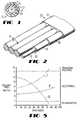
- FIG. 1 shows an end view, in cross section, of a coated optical fiber 10 comprising a glass fiber 12 surrounded by a protective coating system comprising layers 14, 15.
- a protective coating system comprising layers 14, 15.
- glassy optical fiber from a specially prepared, cylindrical preform which has been locally and symmetrically heated to a temperature of about 2000°C.
- a protective coating system is applied to the glass fiber 12 after it has been drawn from the preform which preferably comprises two layers of radiation-cured polymeric materials.
- An inner layer 14 contacts the glass fiber 12 at a glass-coating interface 13 and is referred to as a primary coating material.
- each layer of coating material has a thickness of about 30 micrometers so that the overall diameter of coated fiber 10 is approximately 250 micrometers.
- FIG. 2 there is shown a perspective view of an optical fiber ribbon 20 showing a group of coated glass fibers 10-10 that are held together with an ultraviolet (UV)-curable matrix bonding material 21.
- the group of optical fibers are disposed in a coplanar parallel array, and while only four (4) fibers are shown, such arrays typically comprise twelve (12) individual fibers.
- the modulus of the matrix material has a value less than that of the outer coating layer of the fiber but greater than the modulus of the inner coating layer.
- the matrix material 21 fills the interstices, bonds together the optical fibers, and extends to the outside boundary of the ribbon.
- a typical UV-curable matrix material 21 is a mixture comprising a resin, a diluent and a photoinitiator.
- the resin may include a diethylenic-terminated resin synthesized from a reaction of a hydroxy-terminated alkyl acrylate with the reaction product of a polyester of polyether polyol of molecular weight of 1000 to 6000 Dalton with an aliphatic or aromatic diisoctyanate, or a diethylenic-terminated resin synthesized from the reaction of glycidyl acrylate with a carboxylic-terminated polymer or polyether of molecular weight 1000 to 6000 Dalton.
- the diluent may comprise monofunctional or multifunctional acrylic acid esters having a molecular weight of 100 to 1000 Dalton or N-vinylpyrrolidinone.
- the composition may include ketonic compounds such as diethoxyacetophenone, acetophenone, benzophenone, benzoin, anthraquinone, and benzil dimethyl ketal.
- the bonding matrix may include a resin (50-90%), diluents (5-40%), and a photoinitiator (1-10%). All percentages are by weight unless otherwise noted.
- Other bonding matrices may include a methacrylate, a UV-curing epoxide or an unsaturated polyester. More detailed information regarding bonded arrays of optical fibers is available in the aforementioned U.S. Patent 4,900,126.
- Bonded arrays of optical fibers are commercially available from AT&T under the trademark of AccuRibbon® lightguide cable, and is especially useful for high fiber count installations in the loop and metropolitan area networks where splicing and installation productivity are paramount.
- Each ribbon comprises 12 color-coded fibers for easy identification, and as many as 12 ribbons are stacked together for high density.
- the ribbon stack is surrounded by a core tube which may also contain a filler that prevents the incursion of water in outside plant applications.
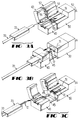
- FIG. 3A-3C illustrate the use of a ribbon-stripping tool such as used by splicing technicians for mass fusion splicing.
- FIG. 3A shows the principal elements of the ribbon stripping tool and associated apparatus. Ribbon 20 is placed within fiber holder 30 to facilitate handling of the fiber during the stripping process.
- the stripping tool comprises holder grip 40 and main body 50 which are used for removing the various layers that surround a bonded fiber array. Lid 53 is closed during the stripping operation and includes an inner surface 54 which cooperates with a heated platen 51 to frictionally hold the outside jacket material surrounding the glass fibers within ribbon 20.
- fiber holder 30 is shown in its closed position around ribbon 20 which about to be inserted into the ribbon-stripping tool.
- the portion of ribbon 20 which is to have its coating layers removed extends beyond the forward end of the fiber holder so that it can be captured between platen 51 and the inside surface 54 of lid 53 when the lid is closed onto the main body 50.
- opposing blades 55, 56 are positioned to cut partially into opposite sides ribbon 20 so that a well-defined break in the coating material can be made.
- the particular tool used is electrically heated from an AC power source which is converted to 12 volts DC for use by a heater element within the main body 50.
- Holder grip 40 is adapted to capture fiber holder 30 therein when its lid 43 is closed.
- FIG. 3B illustrates the movement of holder grip 40 away from the main body 50 of the ribbon-stripping tool.
- Guide rails 45-45 allow the holder grip to slide into engagement with the main body in a controlled manner.
- a heater (not shown) within the main body raises the temperature of platen 51 to a predetermined level which weakens/breaks the adhesive bond at the interface 13 between primary coating 14 and glass fiber 12 (see FIG. 1 or 2) of the various coated fibers.
- a temperature of 100°C for about 2 minutes provides acceptable results.
- a non-crosslinking and non-reactive additive is incorporated into the primary coating formulation which remains mobile (i.e., free to diffuse) in the primary coating after cure so that when the stripping operation is performed the additive will be present at the surface of glass fiber 12 to thereby reduce sliding friction.
- FIG. 3C shows end results of the ribbon stripping process in which glass fibers 12-12 protrude from ribbon 20 which is still held within the fiber holder 30. And matrix material 21 which has just been stripped away remains on the heated platen 51 of the main body 50. Having stripped the matrix and coating materials away from the glass fibers 12-12, FIG. 4A-4C are used for illustrating the vanous possible results of the stripping process and for discussing their acceptability.
- FIG. 4A shows an ideal condition wherein the matrix 21 and coating materials 14, 15 are fully removed from the glass fibers 12-12.
- FIG. 4B shows an ideal condition wherein the matrix 21 and coating materials 14, 15 are fully removed from the glass fibers 12-12.
- FIG. 4B illustrates an unacceptable condition in which the coating materials have clung to the glass fibers so tenaciously that either breakage occurs or large patches remain that cannot be easily removed.
- Coating materials not only protect the glass fiber from abrasion and cushion it against microbending loss, but they also help preserve its tensile strength. However, in order to preserve tensile strength, the coating materials must stay bonded to the glass -- at least until they are stripped off, and then it is desirable that they be fully removable without leaving a residue on the glass. More specifically, the interface between the primary coating material and the glass fiber must be characterized by suitable strength to prevent delamination, and must be such that the coating system can be stripped from the optical fiber without tenacious residues being left on the fiber surface. On the other hand, the surface of the secondary coating material must be such that tacking does not occur between adjacent convolutions of the fiber, resulting in a jerky payoff from a process spool.
- Typical coating materials comprise urethane acrylate liquids whose molecules become crosslinked when exposed to ultraviolet light.
- Various additives are also present that enhance one or more properties of the coating. For example, photoinitiators are added to accelerate the curing process which is important because coated optical fiber is wrapped around spools for storage as soon as it is cured, and manufacturing speed is critical to profitability.
- Curing is the conversion of the liquid coating material to a solid.
- this process is known as free radical cure wherein, upon absorption of light, the photoinitiator components cleave to form free radical pairs which diffuse away from each other and react with acrylate-terminated components to initiate a chain polymerization process.
- coating materials further include diluents, antioxidants, adhesion promoters and, in some cases, additives to improve strippability.
- diluents antioxidants, adhesion promoters and, in some cases, additives to improve strippability.
- primary coating 14 comprises a 30 micron-thick layer of a material that surrounds glass fiber 12. It has a low modulus (e.g., 106 Pa) to cushion the glass fiber against sharp bends that cause loss to a lightwave signal.
- the primary coating illustratively comprises an oligomer (50-80%), a diluent (15-40%), and additives (5-35%).
- the oligomer is derived from polyol ("A") which has been reacted with diisocyanate (“B”), and capped with hydroxy-terminated alkyl acrylate (“C").
- phenoxyethylacrylate is a suitable diluent for use in the optical fiber coating of the present invention which serves to decrease the viscosity of the oligomer resin.
- a carboxy-terminated polyol designated "D”
- R is a combination of C, H or C, H, O
- a glycidyl acrylate, designated "E” comprises the following structure: where: (R5) is an alkyl group
- Various polyols (alcohols containing plural hydroxyl groups) may be used in the oligomer chain including:
- hydrocarbon component For example, maximum acceptable adhesion is provided when only 1% of the hydrocarbon component is added, and minimum acceptable adhesion is provided when 20% of the hydrocarbon component is added.
- the use of hydrocarbon components to achieve these desired results is surprising because formulators historically have avoided the use of non-crosslinkable components due to anticipated and/or observed detrimental properties in the cured form.
- Additives blended into the coating material either bind to the coating material, bind to the glass after the coating material is applied, or are free to migrate. The latter type are sometimes called fugitive because they do not form crosslinks. Unfortunately, many of the fugitive additives cause loss of adhesion or increased surface tack.
- an antioxidant is present in an illustrative amount of about 0.5%
- an adhesion promoter is present in an illustrative amount of 0.5-2.0%
- a photoinitiator is present in an illustrative amount of about 2%.
- hydrocarbon component additives have been found to provide surprisingly beneficial effects on ribbon strippability, with an appropriate degree of adhesion, when they are present in an amount 1-20%.
- polytetrahydrofurandiol (a polyether), having the following structure, is used in forming the oligomer: HO - (O CH2 CH2 CH2 CH2) n - OH
- polytetrahydrofurandiol is used as the hydrocarbon component.
- the preferred hydrocarbon component additive comprises the same polyol used in forming the oligomer.
- FIG. 5 is a graph that illustrates the effect of aging on pullout force for a dual-coated fiber.
- the region which is designated as being "ACCEPTABLE” defines the amount of force needed to remove the coating from a dual-coated fiber without problem.
- curve I When adhesion between the coating material and the glass fiber becomes too great, as indicated by curve I, it is most difficult to remove the coating from the glass fiber without breakage. Frequently, the fiber does not break, and yet some coating material remains attached to the glass after a portion has been removed (see e.g., FIG. 4C).
- curve III When adhesion between the coating material and the glass fiber becomes too little, as indicated by curve III, the above-described problem of delamination occurs which may lead to the incursion of water and consequent weakening of the glass fiber's tensile strength.
- curve II illustrates the beneficial result of adding hydrocarbon components in an amount 1-20% to the coating material. In this situation, the stripping force of the coating material is sufficiently low so that tenacious residues do not remain on the glass fiber, yet sufficiently high that delamination is not a problem.
- the ACCEPTABLE region is quantitatively shown in FIG. 5 based on measurements of the stripping force required to remove coating materials from a dual-coated fiber as a function of time for various coating materials.
Landscapes
- Physics & Mathematics (AREA)
- Chemical & Material Sciences (AREA)
- Life Sciences & Earth Sciences (AREA)
- General Physics & Mathematics (AREA)
- Optics & Photonics (AREA)
- Engineering & Computer Science (AREA)
- General Life Sciences & Earth Sciences (AREA)
- Chemical Kinetics & Catalysis (AREA)
- General Chemical & Material Sciences (AREA)
- Geochemistry & Mineralogy (AREA)
- Materials Engineering (AREA)
- Organic Chemistry (AREA)
- Surface Treatment Of Glass Fibres Or Filaments (AREA)
- Optical Fibers, Optical Fiber Cores, And Optical Fiber Bundles (AREA)
Applications Claiming Priority (2)
| Application Number | Priority Date | Filing Date | Title |
|---|---|---|---|
| US08/170,885 US5373578A (en) | 1993-12-21 | 1993-12-21 | Strippable coating for optical fiber |
| US170885 | 1993-12-21 |
Publications (2)
| Publication Number | Publication Date |
|---|---|
| EP0659701A1 true EP0659701A1 (de) | 1995-06-28 |
| EP0659701B1 EP0659701B1 (de) | 1997-09-10 |
Family
ID=22621676
Family Applications (1)
| Application Number | Title | Priority Date | Filing Date |
|---|---|---|---|
| EP94308907A Expired - Lifetime EP0659701B1 (de) | 1993-12-21 | 1994-12-01 | Abziehbare Beschichtung für optische Faser |
Country Status (5)
| Country | Link |
|---|---|
| US (1) | US5373578A (de) |
| EP (1) | EP0659701B1 (de) |
| JP (1) | JP2883828B2 (de) |
| CA (1) | CA2132992C (de) |
| DE (1) | DE69405525T2 (de) |
Cited By (2)
| Publication number | Priority date | Publication date | Assignee | Title |
|---|---|---|---|---|
| WO2004095103A1 (en) * | 2003-04-17 | 2004-11-04 | 3M Innovative Properties Company | Apparatus useful for guiding fiber optic ribbons into ferrules |
| US7108431B2 (en) | 2003-04-17 | 2006-09-19 | 3M Innovative Properties Company | Ferrule for use in fiber optic connectors |
Families Citing this family (39)
| Publication number | Priority date | Publication date | Assignee | Title |
|---|---|---|---|---|
| CA2082614A1 (en) * | 1992-04-24 | 1993-10-25 | Paul J. Shustack | Organic solvent and water resistant, thermally, oxidatively and hydrolytically stable radiation-curable coatings for optical fibers, optical fibers coated therewith and processes for making same |
| US6052503A (en) * | 1995-09-07 | 2000-04-18 | Dsm N.V. | Optical glass fiber ribbon assembly and radiation curable matrix forming composition |
| WO1997009648A1 (en) * | 1995-09-07 | 1997-03-13 | Dsm N.V. | Optical glass fiber ribbon assembly and radiation curable matrix forming composition |
| US5908873A (en) * | 1995-12-20 | 1999-06-01 | Borden Chemicals, Inc. | Peelable bonded ribbon matrix material; optical fiber bonded ribbon arrays containing same; and process for preparing said optical fiber bonded ribbon arrays |
| CN1221394A (zh) * | 1996-04-10 | 1999-06-30 | Dsm有限公司 | 增加已辐射固化内侧底涂层与玻璃光纤间粘结力的方法 |
| AU4969697A (en) * | 1996-11-08 | 1998-06-03 | Dsm N.V. | Radiation-curable optical glass fiber coating compositions, coated optical glass fibers, and optical glass fiber assemblies |
| US6197422B1 (en) | 1997-05-06 | 2001-03-06 | Dsm, N.V. | Ribbon assemblies and radiation-curable ink compositions for use in forming the ribbon assemblies |
| US6130980A (en) * | 1997-05-06 | 2000-10-10 | Dsm N.V. | Ribbon assemblies and ink coating compositions for use in forming the ribbon assemblies |
| US6085010A (en) * | 1997-06-11 | 2000-07-04 | Dsm N.V. | Optical glass fiber ribbon assemblies and radiation-curable compositions for use in forming ribbon assemblies |
| AU8131998A (en) * | 1997-06-11 | 1998-12-30 | Dsm N.V. | Optical glass fiber ribbon assemblies, matrix forming compositions and ink coating compositions for use in forming ribbon assemblies |
| US6301415B1 (en) | 1997-08-14 | 2001-10-09 | Dsm N.V | Optical glass fiber ribbon assemblies, matrix forming compositions radiation-curable compositions |
| US5977202A (en) * | 1997-09-22 | 1999-11-02 | Dsm N.V. | Radiation-curable compositions having fast cure speed and good adhesion to glass |
| US5946986A (en) * | 1997-10-23 | 1999-09-07 | Amherst International, Inc. | Optical fiber preparation unit |
| US6391936B1 (en) | 1997-12-22 | 2002-05-21 | Dsm N.V. | Radiation-curable oligomers radiation-curable compositions, coated optical glass fibers, and ribbon assemblies |
| US5985952A (en) * | 1998-03-23 | 1999-11-16 | Alvin C. Levy & Associates, Inc. | Radiation curable primary coating composition for an optical fiber |
| US6042943A (en) * | 1998-03-23 | 2000-03-28 | Alvin C. Levy & Associates, Inc. | Optical fiber containing a radiation curable primary coating composition |
| US6110593A (en) * | 1998-05-21 | 2000-08-29 | Dsm N.V. | Radiation-curable optical fiber primary coating system |
| US6040357A (en) * | 1998-05-28 | 2000-03-21 | Dsm N.V. | Method of making a radiation-curable ink composition, radiation-curable ink composition and ribbon assembly |
| US6215934B1 (en) | 1998-10-01 | 2001-04-10 | Lucent Technologies, Inc. | Coated optical fiber with improved strippability |
| US6253013B1 (en) * | 1999-03-29 | 2001-06-26 | Siecor Operations, Llc | Optical fiber arrays |
| US6381390B1 (en) | 1999-04-06 | 2002-04-30 | Alcatel | Color-coded optical fiber ribbon and die for making the same |
| AU779320B2 (en) * | 1999-04-30 | 2005-01-13 | Spi Lasers Uk Limited | An optical fibre arrangement |
| US6261006B1 (en) | 1999-09-24 | 2001-07-17 | Amphenol Corporation | Environmental sealing for fiber optic cable assemblies |
| US6289158B1 (en) * | 1999-11-18 | 2001-09-11 | Lucent Technologies Inc. | Coated optical fiber with enhanced delamination resistance and thermally enhanced strippability |
| US6876799B2 (en) * | 2001-05-09 | 2005-04-05 | Alcatel | Gel-swellable layers on fibers, fiber ribbons and buffer tubes |
| US6714713B2 (en) * | 2002-03-15 | 2004-03-30 | Corning Cable Systems Llc | Optical fiber having a low-shrink buffer layer and methods of manufacturing the same |
| US20050135763A1 (en) * | 2003-12-17 | 2005-06-23 | Gary Drenzek | Optical fiber with a mechanically strippable coating and methods of making the same |
| JP2008090040A (ja) * | 2006-10-03 | 2008-04-17 | Furukawa Electric Co Ltd:The | 光ファイバテープ心線 |
| JP7288429B2 (ja) | 2018-03-08 | 2023-06-07 | 古河電気工業株式会社 | 光ファイバテープ心線及び光ファイバケーブル |
| US10775557B2 (en) | 2018-05-03 | 2020-09-15 | Corning Incorporated | Fiber coatings with low pullout force |
| US10689544B2 (en) | 2018-05-03 | 2020-06-23 | Corning Incorporated | Fiber coatings with low pullout force |
| US11105973B2 (en) | 2019-01-11 | 2021-08-31 | Schott Corporation | Optically enhanced high resolution image guides |
| US12164164B2 (en) | 2019-09-09 | 2024-12-10 | 3M Innovative Properties Company | Optical connector and methods of modifying optical connector |
| US11822117B2 (en) * | 2019-10-08 | 2023-11-21 | Corning Incorporated | Primary coating compositions with improved microbending performance |
| WO2021145102A1 (ja) | 2020-01-14 | 2021-07-22 | 住友電気工業株式会社 | 樹脂組成物、光ファイバ及び光ファイバの製造方法 |
| WO2021145101A1 (ja) | 2020-01-14 | 2021-07-22 | 住友電気工業株式会社 | 樹脂組成物、光ファイバ及び光ファイバの製造方法 |
| EP4174039A4 (de) * | 2020-06-24 | 2024-03-13 | Sumitomo Electric Industries, Ltd. | Harzzusammensetzung, glasfaser und verfahren zur herstellung einer glasfaser |
| WO2022264873A1 (ja) * | 2021-06-14 | 2022-12-22 | 古河電気工業株式会社 | 光ファイバ着色心線、光ファイバリボン、光ファイバリボンケーブル、およびこれらの製造方法 |
| US20230227685A1 (en) * | 2021-11-01 | 2023-07-20 | Ndsu Research Foundation | Bio-based furanic di(meth)acrylates as reactive diluents for uv curable coatings |
Citations (5)
| Publication number | Priority date | Publication date | Assignee | Title |
|---|---|---|---|---|
| JPS58115402A (ja) * | 1981-12-28 | 1983-07-09 | Nippon Telegr & Teleph Corp <Ntt> | 光フアイバ心線 |
| JPS6071550A (ja) * | 1983-09-26 | 1985-04-23 | Nitto Electric Ind Co Ltd | 光学ガラスフアイバ用被覆材料 |
| EP0565798A1 (de) * | 1992-04-16 | 1993-10-20 | Borden, Inc. | UV-Strahlungshärtbare Beschichtung für optische Fasern und damit beschichtete optische Fasern |
| EP0566801A2 (de) * | 1992-04-24 | 1993-10-27 | Borden, Inc. | Organische Lösungsmittel und wasserresistente, thermisch, oxidatif und hydrolytisch stabile strahlenhärtbare Beschichtungen für optische Fasern, damit beschichtete optische Fasern und Verfahren zur deren Herstellung |
| WO1993021248A1 (en) * | 1992-04-20 | 1993-10-28 | Dsm Desotech, Inc. | Liquid curable resin composition |
Family Cites Families (12)
| Publication number | Priority date | Publication date | Assignee | Title |
|---|---|---|---|---|
| US4472021A (en) * | 1982-12-10 | 1984-09-18 | Desoto, Inc. | Strippable radiation-cured coatings for optical fiber and method |
| US4474830A (en) * | 1982-12-29 | 1984-10-02 | At&T Bell Laboratories | Multiple coating of fibers |
| JPS61215236A (ja) * | 1985-03-15 | 1986-09-25 | Nippon Paint Co Ltd | 光フアイバ−被覆組成物 |
| US5136679A (en) * | 1985-07-23 | 1992-08-04 | U.S. Philips Corp. | Optical glass fibre having a synthetic resin coating and curable elastomer forming material |
| DE3710240A1 (de) * | 1987-03-27 | 1988-10-06 | Siemens Ag | Optische glasfaser mit einer primaerbeschichtung aus acrylsaeureestergruppenhaltigen organopolysiloxanen |
| US4851165A (en) * | 1987-09-02 | 1989-07-25 | American Telephone And Telegraph Company At&T Bell Laboratories | Methods of and apparatus for coating optical fiber |
| US4900126A (en) * | 1988-06-30 | 1990-02-13 | American Telephone & Telegraph Co. | Bonded array of transmission media |
| CA1321671C (en) * | 1989-05-11 | 1993-08-24 | Paul J. Shustack | Ultraviolet radiation-curable coatings for optical fibers and optical fibers coated therewith |
| US5011260A (en) * | 1989-07-26 | 1991-04-30 | At&T Bell Laboratories | Buffered optical fiber having a strippable buffer layer |
| US5062685A (en) * | 1989-10-11 | 1991-11-05 | Corning Incorporated | Coated optical fibers and cables and method |
| US5015068A (en) * | 1990-02-15 | 1991-05-14 | At&T Bell Laboratories | Coated optical fiber and methods of making |
| US5181269A (en) * | 1991-09-17 | 1993-01-19 | At&T Bell Laboratories | Optical fiber including acidic coating system |
-
1993
- 1993-12-21 US US08/170,885 patent/US5373578A/en not_active Expired - Lifetime
-
1994
- 1994-09-27 CA CA002132992A patent/CA2132992C/en not_active Expired - Fee Related
- 1994-12-01 DE DE69405525T patent/DE69405525T2/de not_active Expired - Fee Related
- 1994-12-01 EP EP94308907A patent/EP0659701B1/de not_active Expired - Lifetime
- 1994-12-21 JP JP6335123A patent/JP2883828B2/ja not_active Expired - Lifetime
Patent Citations (5)
| Publication number | Priority date | Publication date | Assignee | Title |
|---|---|---|---|---|
| JPS58115402A (ja) * | 1981-12-28 | 1983-07-09 | Nippon Telegr & Teleph Corp <Ntt> | 光フアイバ心線 |
| JPS6071550A (ja) * | 1983-09-26 | 1985-04-23 | Nitto Electric Ind Co Ltd | 光学ガラスフアイバ用被覆材料 |
| EP0565798A1 (de) * | 1992-04-16 | 1993-10-20 | Borden, Inc. | UV-Strahlungshärtbare Beschichtung für optische Fasern und damit beschichtete optische Fasern |
| WO1993021248A1 (en) * | 1992-04-20 | 1993-10-28 | Dsm Desotech, Inc. | Liquid curable resin composition |
| EP0566801A2 (de) * | 1992-04-24 | 1993-10-27 | Borden, Inc. | Organische Lösungsmittel und wasserresistente, thermisch, oxidatif und hydrolytisch stabile strahlenhärtbare Beschichtungen für optische Fasern, damit beschichtete optische Fasern und Verfahren zur deren Herstellung |
Non-Patent Citations (2)
| Title |
|---|
| DATABASE WPI Section Ch Week 8522, Derwent World Patents Index; Class A89, AN 85-132574 * |
| PATENT ABSTRACTS OF JAPAN vol. 007, no. 224 (P - 227) 5 October 1983 (1983-10-05) * |
Cited By (3)
| Publication number | Priority date | Publication date | Assignee | Title |
|---|---|---|---|---|
| WO2004095103A1 (en) * | 2003-04-17 | 2004-11-04 | 3M Innovative Properties Company | Apparatus useful for guiding fiber optic ribbons into ferrules |
| US6973242B2 (en) | 2003-04-17 | 2005-12-06 | 3M Innovative Properties Company | Apparatus useful for guiding fiber optic ribbons into ferrules |
| US7108431B2 (en) | 2003-04-17 | 2006-09-19 | 3M Innovative Properties Company | Ferrule for use in fiber optic connectors |
Also Published As
| Publication number | Publication date |
|---|---|
| JP2883828B2 (ja) | 1999-04-19 |
| DE69405525D1 (de) | 1997-10-16 |
| US5373578A (en) | 1994-12-13 |
| DE69405525T2 (de) | 1998-03-26 |
| EP0659701B1 (de) | 1997-09-10 |
| CA2132992C (en) | 1997-10-28 |
| CA2132992A1 (en) | 1995-06-22 |
| JPH07215737A (ja) | 1995-08-15 |
Similar Documents
| Publication | Publication Date | Title |
|---|---|---|
| EP0659701B1 (de) | Abziehbare Beschichtung für optische Faser | |
| JP7384827B2 (ja) | 小径の低減衰光ファイバ | |
| US6014488A (en) | Coated optical fibers having strippable primary coatings and processes for making and using same | |
| US6243523B1 (en) | Coated optical fiber with increased modulus and thermally enhanced strippability | |
| EP0780712B1 (de) | Abziehbares Bandkabelmaterial, faseroptische Flachbandkabel und Verfahren zu deren Herstellung | |
| JP7839597B2 (ja) | 高密度ケーブル及び相互接続のための、薄型コーティングを備えたシングルモード光ファイバ | |
| EP0565798B1 (de) | UV-Strahlungshärtbare Beschichtung für optische Fasern und damit beschichtete optische Fasern | |
| EP3911980B1 (de) | Faseroptisches kabel mit hoher faseranzahl | |
| US20050031283A1 (en) | Optical fiber coating system and coated optical fiber | |
| EP1362835A1 (de) | Beschichtete lichtleitfaser, lichtleitfaserbandkern, bei dem diese verwendet wird, und lichtleitfasereinheit | |
| KR20020067060A (ko) | 팬던트 히드록실 관능기를 갖는 모노머를 포함하는 1차코팅제 조성물로 제조된 광섬유 | |
| JP2022521898A (ja) | 耐穿刺性小径マルチモード光ファイバ | |
| AU2002257795A1 (en) | Method for controlling microbending induced attenuation losses in an optical fiber | |
| JP2022521899A (ja) | クラッドの厚さが削減されたマルチモード光ファイバ | |
| US6215934B1 (en) | Coated optical fiber with improved strippability | |
| US6289158B1 (en) | Coated optical fiber with enhanced delamination resistance and thermally enhanced strippability | |
| JP2012533771A (ja) | 光ファイバリボン及び低オリゴマー含有量を有するリボンマトリックス材料 | |
| KR100483980B1 (ko) | 열 박리가능한 광섬유 리본 | |
| US20050069272A1 (en) | Coated optical fiber and optical fiber coating system including a hydrophilic primary coating | |
| WO2022138119A1 (ja) | 樹脂組成物、樹脂組成物の製造方法、光ファイバ、光ファイバの製造方法、光ファイバリボン、及び光ファイバケーブル | |
| AU712024B2 (en) | Optical glass fiber ribbon assembly and radiation curable matrix forming composition | |
| CN1194609A (zh) | 使用涂料添加剂增强剥离性的带状光缆 | |
| JP2011033931A (ja) | 被覆光ファイバ | |
| WO2025249239A1 (ja) | 光ファイバ、光ファイバリボン、および光ファイバケーブル | |
| AU2008200763B2 (en) | Optical fiber |
Legal Events
| Date | Code | Title | Description |
|---|---|---|---|
| PUAI | Public reference made under article 153(3) epc to a published international application that has entered the european phase |
Free format text: ORIGINAL CODE: 0009012 |
|
| AK | Designated contracting states |
Kind code of ref document: A1 Designated state(s): DE FR GB |
|
| RIN1 | Information on inventor provided before grant (corrected) |
Inventor name: SHEPHERD, LLOYD Inventor name: TAYLOR, CARL RAYMOND Inventor name: PETISCE, JAMES RAYMOND Inventor name: PARKER, THEODORE LANCE, |
|
| 17P | Request for examination filed |
Effective date: 19951207 |
|
| 17Q | First examination report despatched |
Effective date: 19960603 |
|
| GRAG | Despatch of communication of intention to grant |
Free format text: ORIGINAL CODE: EPIDOS AGRA |
|
| GRAH | Despatch of communication of intention to grant a patent |
Free format text: ORIGINAL CODE: EPIDOS IGRA |
|
| GRAH | Despatch of communication of intention to grant a patent |
Free format text: ORIGINAL CODE: EPIDOS IGRA |
|
| GRAA | (expected) grant |
Free format text: ORIGINAL CODE: 0009210 |
|
| AK | Designated contracting states |
Kind code of ref document: B1 Designated state(s): DE FR GB |
|
| REF | Corresponds to: |
Ref document number: 69405525 Country of ref document: DE Date of ref document: 19971016 |
|
| ET | Fr: translation filed | ||
| PLBE | No opposition filed within time limit |
Free format text: ORIGINAL CODE: 0009261 |
|
| STAA | Information on the status of an ep patent application or granted ep patent |
Free format text: STATUS: NO OPPOSITION FILED WITHIN TIME LIMIT |
|
| 26N | No opposition filed | ||
| REG | Reference to a national code |
Ref country code: GB Ref legal event code: IF02 |
|
| PGFP | Annual fee paid to national office [announced via postgrant information from national office to epo] |
Ref country code: DE Payment date: 20090202 Year of fee payment: 15 |
|
| PGFP | Annual fee paid to national office [announced via postgrant information from national office to epo] |
Ref country code: GB Payment date: 20081229 Year of fee payment: 15 |
|
| PGFP | Annual fee paid to national office [announced via postgrant information from national office to epo] |
Ref country code: FR Payment date: 20081217 Year of fee payment: 15 |
|
| GBPC | Gb: european patent ceased through non-payment of renewal fee |
Effective date: 20091201 |
|
| REG | Reference to a national code |
Ref country code: FR Ref legal event code: ST Effective date: 20100831 |
|
| PG25 | Lapsed in a contracting state [announced via postgrant information from national office to epo] |
Ref country code: FR Free format text: LAPSE BECAUSE OF NON-PAYMENT OF DUE FEES Effective date: 20091231 |
|
| PG25 | Lapsed in a contracting state [announced via postgrant information from national office to epo] |
Ref country code: DE Free format text: LAPSE BECAUSE OF NON-PAYMENT OF DUE FEES Effective date: 20100701 |
|
| PG25 | Lapsed in a contracting state [announced via postgrant information from national office to epo] |
Ref country code: GB Free format text: LAPSE BECAUSE OF NON-PAYMENT OF DUE FEES Effective date: 20091201 |