EP0659916A1 - Webschaftkupplung und Vorrichtung zum simultanen Öffnen und Schliessen einer Vielzahl von Webschaftkupplungen in einer Webmaschine - Google Patents
Webschaftkupplung und Vorrichtung zum simultanen Öffnen und Schliessen einer Vielzahl von Webschaftkupplungen in einer Webmaschine Download PDFInfo
- Publication number
- EP0659916A1 EP0659916A1 EP94118631A EP94118631A EP0659916A1 EP 0659916 A1 EP0659916 A1 EP 0659916A1 EP 94118631 A EP94118631 A EP 94118631A EP 94118631 A EP94118631 A EP 94118631A EP 0659916 A1 EP0659916 A1 EP 0659916A1
- Authority
- EP
- European Patent Office
- Prior art keywords
- coupling
- shaft
- coupling part
- heald frame
- lever
- Prior art date
- Legal status (The legal status is an assumption and is not a legal conclusion. Google has not performed a legal analysis and makes no representation as to the accuracy of the status listed.)
- Granted
Links
- 238000010168 coupling process Methods 0.000 title claims abstract description 97
- 230000008878 coupling Effects 0.000 title claims abstract description 96
- 238000005859 coupling reaction Methods 0.000 title claims abstract description 96
- 230000007246 mechanism Effects 0.000 claims abstract description 12
- 238000009941 weaving Methods 0.000 claims description 6
- 230000013011 mating Effects 0.000 claims 1
- 230000008859 change Effects 0.000 description 2
- 238000000034 method Methods 0.000 description 2
- 230000008569 process Effects 0.000 description 2
- 230000009471 action Effects 0.000 description 1
- 230000001154 acute effect Effects 0.000 description 1
- 239000000835 fiber Substances 0.000 description 1
Images


Classifications
-
- D—TEXTILES; PAPER
- D03—WEAVING
- D03C—SHEDDING MECHANISMS; PATTERN CARDS OR CHAINS; PUNCHING OF CARDS; DESIGNING PATTERNS
- D03C9/00—Healds; Heald frames
- D03C9/06—Heald frames
- D03C9/0683—Arrangements or means for the linking to the drive system
-
- D—TEXTILES; PAPER
- D03—WEAVING
- D03C—SHEDDING MECHANISMS; PATTERN CARDS OR CHAINS; PUNCHING OF CARDS; DESIGNING PATTERNS
- D03C9/00—Healds; Heald frames
-
- Y—GENERAL TAGGING OF NEW TECHNOLOGICAL DEVELOPMENTS; GENERAL TAGGING OF CROSS-SECTIONAL TECHNOLOGIES SPANNING OVER SEVERAL SECTIONS OF THE IPC; TECHNICAL SUBJECTS COVERED BY FORMER USPC CROSS-REFERENCE ART COLLECTIONS [XRACs] AND DIGESTS
- Y10—TECHNICAL SUBJECTS COVERED BY FORMER USPC
- Y10T—TECHNICAL SUBJECTS COVERED BY FORMER US CLASSIFICATION
- Y10T292/00—Closure fasteners
- Y10T292/08—Bolts
- Y10T292/1043—Swinging
-
- Y—GENERAL TAGGING OF NEW TECHNOLOGICAL DEVELOPMENTS; GENERAL TAGGING OF CROSS-SECTIONAL TECHNOLOGIES SPANNING OVER SEVERAL SECTIONS OF THE IPC; TECHNICAL SUBJECTS COVERED BY FORMER USPC CROSS-REFERENCE ART COLLECTIONS [XRACs] AND DIGESTS
- Y10—TECHNICAL SUBJECTS COVERED BY FORMER USPC
- Y10T—TECHNICAL SUBJECTS COVERED BY FORMER US CLASSIFICATION
- Y10T292/00—Closure fasteners
- Y10T292/68—Keepers
- Y10T292/696—With movable dog, catch or striker
- Y10T292/702—Pivoted or swinging
-
- Y—GENERAL TAGGING OF NEW TECHNOLOGICAL DEVELOPMENTS; GENERAL TAGGING OF CROSS-SECTIONAL TECHNOLOGIES SPANNING OVER SEVERAL SECTIONS OF THE IPC; TECHNICAL SUBJECTS COVERED BY FORMER USPC CROSS-REFERENCE ART COLLECTIONS [XRACs] AND DIGESTS
- Y10—TECHNICAL SUBJECTS COVERED BY FORMER USPC
- Y10T—TECHNICAL SUBJECTS COVERED BY FORMER US CLASSIFICATION
- Y10T403/00—Joints and connections
- Y10T403/59—Manually releaseable latch type
- Y10T403/599—Spring biased manipulator
Definitions
- the invention relates to a heald frame coupling and a device for simultaneously opening and closing a plurality of heald frame couplings in a weaving machine.
- Each heald frame coupling is known to consist of one or more shaft-side coupling elements and one or more drive-side coupling elements which engage in a form-fitting manner in the coupled state and produce an operative connection between the heald frames and the associated drive elements.
- EP 0 407 335 discloses a heald frame coupling in combination with a device for simultaneous opening and closing of a large number of heald frame couplings to reduce the time-consuming coupling and uncoupling processes involved in changing the harness.
- the specially designed heald frame couplings after the heald frames have been brought into the so-called shaft alignment, can be simultaneously decoupled or coupled by an actuating tool which is fixed to the machine and which engages around individual or all of the shaft couplings and which, after a rotary adjustment, applies a tension force to the drive-side heald frame couplings become.
- heald frame couplings require a relatively high production outlay both for the drive-side and for the shaft-side coupling part due to the geometric shape and the large number of surfaces that transmit the tensile and impact forces.
- the object of the invention is to provide a shaft coupling, the coupling parts of which have a simple geometric design and require little production effort. It is a further object of the invention to dispense with a single additional securing element, as required by the known shaft coupling according to European patent application 0 407 335, and rather to integrate the locking of the coupling into the overall solution. Furthermore, it is an object of the invention to provide, in combination with each individual shaft coupling, a device for simultaneous coupling and uncoupling which is arranged outside the range of movement of the shafts and their drives and which, in the event of a shaft change, the shaft pulling or pushing rod in the holding position required for the coupling process.
- the problems are solved according to the features of claim 1 and according to the features of independent claim 6.
- the main advantages of the solution according to the invention are that the individual coupling parts have a simple geometric shape and therefore do not require complex production, that there is no need for a separate securing device to prevent the clutch from opening independently, and that the device which accomplishes the simultaneous coupling and uncoupling is outside the device Movement range of the shaft and shaft pull is arranged and thus is not directly exposed to the fiber fly occurring in the area of the weaving machine.
- a carrier 1 similar to a bearing block, is connected to the heald frame 3, which is indicated by way of illustration, by means of the symbolically represented screws 2.
- the shaft-side coupling part 5 mounted rotatably about the carrier axis 4 is received by the carrier 1.
- the coupling part 5 designed in the manner of a locking wedge, as shown in FIG. 2, has on both sides of its longitudinal axis 6 a supporting surface 7 or 8 running in a horizontal plane, which in the coupled state are in contact with corresponding counter-supporting surfaces 9, 10 of the drive-side coupling part 11 . This limits the vertical movement of the two interlocking coupling parts 5, 11.
- the drive-side coupling part 11 consists of a first and a second bearing body 16, 17 which can be connected to the push-pull rod 15 and has the abovementioned support surfaces 9 and 10, see also FIG. 3.
- the drive-side coupling elements which cooperate with the coupling part 5, such as a contact piece 18 which comes into contact with the contact surface 12 of the coupling part 5 and a pawl 14 which is pivotably mounted about the axis 19 and is connected to a joint mechanism 20, whose support surface 14a comes into contact with the support surface 13a of the coupling part 5, see also FIG. 2.
- the shaft coupling 5, 11 designed according to the invention therefore dispenses with an additional locking device.
- the articulated mechanism 20, which is connected to the pawl 14 via the pivot point 23, consists, for example, of a triangular lever 25, each with a pivot or pivot point 23, 24, 26 in the corner regions.
- the individual imaginary connecting lines to the pivot point 23 and to the articulation points 24, 26 form an isosceles triangle.
- the pivot point 23 forms the rotatable connection between the pawl 14 and the articulated mechanism 20 or the triangular lever 25.
- a second articulation point is formed by the spring axis 24.
- the third articulation point is formed by the axle shaft 26a, on which the angle lever 28 pivotable about the axle shaft 27 in the drive-side coupling part 11 engages.
- the lever arm 28a of the angle fog 28 is articulatedly connected to the triangular lever 25 via the axle shaft 26a.
- the lever arm 28b carries, for example, a roller 30 carried by a roller axis 29, which roller can be operatively connected to an actuating device 31 for the purpose of coupling and uncoupling.
- the device 31 consists of an adjusting shaft 31a rotatably mounted in a weaving machine part, not shown, to which a plurality of actuating elements 31b are successively connected in a rotationally fixed manner.
- Each of the actuating elements 31b is designed in such a way that when the coupling part 5 is completely unlocked, a positive connection is established between the actuating element 31b and the angle lever 28.
- the actuating element 31b has a contact surface 32 which grips the roller 30 and which merges into a guide designed as a curve 33 with an end limitation.
- the roller 30 rests in the uncoupled state of the heald frame coupling, for example during the change of the harness.
- the positive connection between the actuating element 31b and the roller 30 is canceled by pivoting the actuating element 31b back in the direction of the arrow; the pawl 14 is automatically pivoted under the action of the tensile force of the tension spring 22 into the recess of the coupling part 5 precentered by the contact piece 18 and a point 14b on the circumference of the pawl head of the pawl 14, see also FIG. 1.
- the manner in which the actuating shaft 31a is driven and the control of its drive can be left to the person skilled in the art.
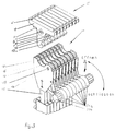
- FIG. 3 shows the shaft-side and drive-side coupling parts 5 and 11, which are arranged close to one another in the manner of a package.
- the shaft-side coupling parts 5 are shown here separately from the drive-side coupling parts 11.
- the adjusting shaft 31a is designed as a splined shaft; it penetrates the actuating elements 31b, which thus sit on the actuating shaft 31a in a rotationally fixed manner.
- the individual actuating elements 31b are simultaneously brought out of operative connection or in operative connection with the respective lever 28 of the individual joint mechanisms 20, as shown in FIGS. 1 and 2. This means that all shaft couplings can either be opened simultaneously or closed simultaneously.
Landscapes
- Engineering & Computer Science (AREA)
- Textile Engineering (AREA)
- Looms (AREA)
Abstract
Description
- Die Erfindung betrifft eine Webschaftkupplung und eine Vorrichtung zum simultanen Öffnen und Schließen einer Vielzahl von Webschaftkupplungen in einer Webmaschine.
Jede Webschaftkupplung besteht bekanntermaßen aus einem oder mehreren schaftseitigen Kupplungselementen und aus einem oder mehreren antriebsseitigen Kupplungselementen, die im gekuppelten Zustand formschlüssig ineinander greifen und eine Wirkverbindung zwischen den Webschäften und den zugehörigen Antriebsorganen herstellen. - Bekannte Webschaftkupplungen bedingen zum Kuppeln und Entkuppeln der Webschäfte mit bzw. von den Antriebsorganen Betätigungswerkzeuge, mit denen jede einzelne Wirkverbindung zwischen dem Webschaft und dem Antriebsorgan separat aufgehoben wird.
Derartige Schaftkupplungsvorgänge erfordern im Vorfeld des Webprozesses, d.h. beim Webgeschirrwechsel einen erheblichen Zeitaufwand in den Webereien. Zur Reduzierung der beim Webgeschirrwechsel anfallenden zeitaufwendigen Kupplungs- und Entkupplungsvorgänge ist aus der EP 0 407 335 eine Webschaftkupplung in Kombination mit einer Vorrichtung zum simultanen Öffnen und Schließen einer Vielzahl von Webschaftkupplungen bekannt.
Danach können die speziell ausgebildeten Webschaftkupplungen, nachdem die Webschäfte in die sogenannte Schaftgleichstellung gebracht worden sind, von einem maschinenfest angeordneten Betätigungswerkzeug, das einzelne oder die Gesamtheit der Schaftkupplungen umgreift und das nach einer rotatorischen Verstellung eine Spannkraft auf die antriebsseitigen Webschaftkupplungen aufbringt, simultan entkuppelt oder gekuppelt werden. - Derartige Webschaftkupplungen erfordern sowohl für das antriebsseitige als auch für das schaftseitige Kupplungsteil aufgrund der geometrischen Form und der Vielzahl der die Zug- und Stoßkräfte übertragenden Flächen einen relativ hohen Fertigungsaufwand.
- Aufgabe der Erfindung ist es, eine Schaftkupplung zu schaffen, deren Kupplungsteile eine einfache geometrische Ausbildung aufweisen und einen geringen Fertigungsaufwand erfordern.
Es ist ferner Aufgabe der Erfindung auf ein einzelnes zusätzliches Sicherungselement, wie es die bekannte Schaftkupplung nach der europäischen Patentanmeldung 0 407 335 erfordert, zu verzichten und vielmehr die Verriegelung der Kupplung in die Gesamtlösung zu integrieren.
Des weiteren ist es Aufgabe der Erfindung, in Kombination mit jeder einzelnen Schaftkupplung eine Vorrichtung zum simultanen Kuppeln und Entkuppeln zu schaffen, die außerhalb des Bewegungsbereichs der Schäfte und ihrer Antriebe angeordnet ist und die im Falle eines Schaftwechsels die Schaftzug- bzw. -schubstange in der für den Kupplungsvorgang erforderlichen Wartestellung hält. - Die Aufgabenstellungen werden gemäß der Merkmale des Anspruchs 1 und gemäß der Merkmale des unabhängigen Anspruchs 6 gelöst.
Die wesentlichen Vorteile der erfindungsgemäßen Lösung bestehen darin, daß die einzelnen Kupplungsteile eine einfache geometrische Form aufweisen und daher keiner aufwendigen Fertigung bedürfen, daß auf eine separate Sicherungseinrichtung gegen selbstständiges Öffnen der Kupplung verzichtet werden kann und daß die das simultane Kuppeln und Entkuppeln bewerkstelligende Vorrichtung außerhalb des Bewegungsbereichs von Schaft und Schaftzug angeordnet ist und damit dem im Bereich der Webmaschine auftretenden Faserflug nicht direkt ausgesetzt ist. - Die Erfindung wird im folgenden anhand eines in den Zeichnungen dargestellten Ausführungsbeispiels näher beschrieben. Es zeigen:
- Fig. 1
- einen Längsschnitt der Webschaftkupplung im gekuppelten Zustand mit dem schaftseitigen und dem antriebsseitigen Anschluß,
- Fig. 2
- einen Längsschnitt durch den antriebsseitigen und den webschaftseitigen Kupplungsteil im entkuppelten Zustand und die Vorrichtung zum simultanen Öffnen und Schließen der Kupplung in Eingriff mit dem antriebsseitigen Kupplungsteil,
- Fig. 3
- eine perspektivische Ansicht einer Vielzahl von Webschaftkupplungen in geöffnetem Zustand und in Verbindung mit der Vorrichtung zum simultanen Öffnen und Schließen der Kupplungen.
- Wie Figur 1 zeigt, ist ein Träger 1, ähnlich einem Lagerbock ausgebildet, über die symbolhaft dargestellten Schrauben 2 mit dem andeutungsweise dargestellten Webschaft 3 verbunden. Von dem Träger 1 wird das um die Trägerachse 4 drehbeweglich gelagerte schaftseitige Kupplungsteil 5 aufgenommen. Das in Art eines Schließkeils ausgebildete Kupplungsteil 5 besitzt, wie Figur 2 zeigt, zu beiden Seiten seiner Längsachse 6 jeweils eine in horizontaler Ebene verlaufende Stützfläche 7 bzw. 8, die im gekuppelten Zustand mit entsprechenden Gegenstützflächen 9,10 des antriebsseitigen Kupplungsteil 11 in Kontakt stehen. Dadurch ist die vertikale Bewegung der beiden ineinander greifenden Kupplungsteile 5,11 begrenzt.
- Während die Stützfläche 8 aus ihrem horizontalen Verlauf in eine parallel zur Längsachse 6 des Kupplungsteils 5 verlaufende rechte Anlagefläche 12 übergeht, geht die Stützfläche 7 in eine zunächst spitzwinklig zur Längsachse 6 des Kupplungsteils 5 verlaufende Anlagefläche 13 über, die im Endbereich des Kupplungsteils 5 eine schräg zur o.g. Längsachse 6 verlaufende Stützfläche 13a für eine Klinke 14 ausbildet.
Das antriebsseitige Kupplungsteil 11 besteht aus einem ersten und einem zweiten mit der Schub-Zugstange 15 verbindbaren Lagerkörper 16,17 mit den vorstehend erwähnten Stützflächen 9 bzw. 10, siehe auch Fig. 3.
Zwischen diesen Lagerkörpern 16,17 sind die mit dem Kupplungsteil 5 zusammenwirkenden antriebsseitigen Kupplungselemente angeordnet, wie ein mit der Anlagefläche 12 des Kupplungsteils 5 zur Anlage kommendes Anlagestück 18 und eine schwenkbar um die Achse 19 gelagerte und mit einem Gelenkmechanismus 20 in Verbindung stehende Klinke 14, deren Stützfläche 14a mit der Stützfläche 13a des Kupplungsteils 5 zur Anlage kommt, sieh auch Fig. 2. - Durch die Zugfeder 22, die innerhalb des antriebsseitigen Kupplungsteils 11 einerseits an einer Federachse 21 und andererseits an dem Gelenkmechanismus 20 mit Federachse 24 angreift, wird aufgrund einer entsprechenden Festlegung des Schwenkpunktes 23 für den Dreieckhebel 25 des Gelenkmechanismus 20 und für die Federachse 24 der Zugfeder 22 am Gelenkmechanismus 20, ein selbstständiges Lösen der Kupplungsteile 5,11 ausgeschlossen.
Die erfindungsgemäß ausgebildete Schaftkupplung 5,11 verzichtet damit, im Gegensatz zu der bekannten Lösung, auf eine zusätzliche Verriegelungseinrichtung. - Der mit der Klinke 14 über den Schwenkpunkt 23 in Verbindung stehende Gelenkmechanismus 20 besteht beispielsweise aus einem Dreieckhebel 25 mit jeweils einem in den Eckbereichen vorhandenen Schwenk- bzw. Anlenkpunkt 23,24,26. Die einzelnen imaginären Verbindungslinien zu dem Schwenkpunkt 23 und zu den Anlenkpunkten 24,26 bilden ein gleichschenkliges Dreieck.
- Der Schwenkpunkt 23 bildet die drehbewegliche Verbindung zwischen der Klinke 14 und dem Gelenkmechanismus 20, respektive dem Dreieckhebel 25.
Ein zweiter Anlenkpunkt wird von der Federachse 24 gebildet. Den dritten Anlenkpunkt bildet die Achswelle 26a, an welcher der im antriebsseitigen Kupplungsteil 11 um die Achswelle 27 schwenkbare Winkelhebel 28 angreift.
Der Hebelarm 28a des Winkelnebels 28 ist gelenkig über die Achswelle 26a mit dem Dreieckhebel 25 verbunden.
Der Hebelarm 28b trägt an seinem freien Ende z.B. eine von einer Rollenachse 29 getragene Rolle 30, die zum Zwecke des Kuppelns und Entkuppelns mit einer Betätigungsvorrichtung 31 in Wirkverbindung bringbar ist. - In Figur 2 ist das schaftseitige Kupplungsteil 5 von dem antriebsseitigen Kupplungsteil 11 getrennt; die Klinke 14 wurde dazu durch Betätigung des Gelenkmechanismus 20 im Sinne eines Spannens der Zugfeder 22 außer Eingriff vom Kupplungsteil 5 gebracht.
Bei Betätigung des Winkelhebels 28 erfolgt mit der erfindungsgemäß ausgebildeten Vorrichtung 31 das simultane Kuppeln bzw. Entkuppeln aller Webschäfte 3 von ihrem antriebsseitigen Kupplungsteil 11, das mit der jeweiligen Schub- bzw. Zugstange 15 verbunden ist. - Die Vorrichtung 31 besteht aus einer drehbar in einem nicht dargestellten Webmaschinenteil gelagerten Stellwelle 31a, mit welcher eine Vielzahl von Betätigungselementen 31b nacheinander drehfest verbunden ist. Jedes der Betätigungselemente 31b ist so ausgelegt, daß bei vollständig entriegeltem Kupplungsteil 5 zwischen dem Betätigungselement 31b und dem Winkelhebel 28 eine formschlüssige Verbindung hergestellt ist. Dazu weist das Betätigungselement 31b eine die Rolle 30 erfassende Kontaktfläche 32 auf, die in eine als Kurve 33 ausgebildete Führung mit Endbegrenzung übergeht.
- In dieser Kurve ruht die Rolle 30 im entkuppelten Zustand der Webschaftkupplung z.B. während des Webgeschirrwechsels.
Nach dem Einsetzen des schaftseitigen Kupplungsteil 5 in das antriebsseitige Kupplungsteil 11 wird die formschlüssige Verbindung zwischen dem Betätigungselement 31b und der Rolle 30 durch Zurückschwenken des Betätigungselements 31b in Pfeilrichtung "schließen" aufgehoben; die Klinke 14 wird automatisch unter Wirkung der Zugkraft der Zugfeder 22 in die Ausnehmung des durch das Anlagestück 18 und einem Punkt 14b am Umfang des Klinkenkopfes der Klinke 14 vorzentrierten Kupplungsteils 5 eingeschwenkt, siehe auch Figur 1.
Die Art und Weise des Antriebes der Stellwelle 31a und die Steuerung ihres Antriebs kann dem Fachmann überlassen bleiben. - Figur 3 zeigt die schaftseitigen und antriebsseitigen Kupplungsteile 5 bzw. 11 dicht aneinander liegend in Art eines Paketes ausgebildet.
Die schaftseitigen Kupplungsteile 5 sind hier von den antriebsseitigen Kupplungsteilen 11 getrennt dargestellt.
Die Stellwelle 31a ist als Vielkeilwelle ausgebildet; sie durchdringt die Betätigungselemente 31b, die damit drehfest auf der Stellwelle 31a sitzen.
Durch eine Drehbewegung der Stellwelle 31a in die angegebenen Pfeilrichtungen "Öffnen" bzw. "Schließen" werden die einzelnen Betätigungselemente 31b simultan außer Wirkverbindung oder in Wirkverbindung mit dem jeweiligen Hebel 28 der einzelnen Gelenkmechanismen 20 gebracht, wie in Figur 1 und 2 dargestellt.
Damit können alle Schaftkupplungen entweder gleichzeitig geöffnet oder gleichzeitig geschlossen werden. -
- 1
- Träger
- 2
- Schraube
- 3
- Webschaft
- 4
- Trägerachse
- 5
- Kupplungsteil
- 6
- Längsachse
- 7
- Stützfläche
- 8
- Stützfläche
- 9
- Gegenstützfläche
- 10
- Gegenstützfläche
- 11
- Kupplungsteil
- 12
- Anlagefläche
- 13
- Anlagefläche
- 13a
- Stützfläche
- 14
- Klinke
- 14a
- Stützfläche
- 14b
- Punkt
- 15
- Schub-Zugstange
- 16
- Lagerkörper
- 17
- Lagerkörper
- 18
- Anlagestück
- 18a
- Anlagefläche
- 19
- Achse
- 20
- Gelenkmechanismus
- 21
- Federachse
- 22
- Zugfeder
- 23
- Schwenkpunkt
- 24
- Federachse
- 25
- Dreieckhebel
- 26
- Anlenkpunkt
- 26a
- Achswelle
- 27
- Achswelle
- 28
- Winkelhebel
- 28a
- Hebelarm
- 28b
- Hebelarm
- 29
- Rollenachse
- 30
- Rolle
- 31
- Betätigungsvorrichtung
- 31a
- Stellwelle
- 31b
- Betätigungselement
- 32
- Kontaktfläche
- 33
- Kurve
Claims (7)
- Webschaftkupplung und Vorrichtung zum simultanen Kuppeln und Entkuppeln der Webschäfte mit bzw. von den Schaftantriebsorganen einer Webmaschine, wobei jede Webschaftkupplung aus einem ersten schaftseitigen Kupplungsteil mit wenigstens einer Kupplungsfläche und aus einem zweiten antriebsseitigen Kupplungsteil besteht, mit welchem eine gegen das erste Kupplungsteil um eine Achse schwenkbar angeordnete Klinke verbindbar ist, die wenigstens eine Gegenkupplungsfläche zur Herstellung einer Formschlußverbindung mit dem antriebsseitigen Kupplungsteil aufweist, dadurch gekennzeichnet, daß im zweiten Kupplungsteil (11) beabstandet von der Achse (19) an der Klinke (14) ein durch eine Zugfeder (22) belasteter Dreieckhebel (25) eines Gelenkmechanismus (20) an einem Schwenkpunkt (23) angreift, daß der Dreieckhebel (25) mit einem ersten Hebelarm (28a) eines im zweiten Kupplungsteil (11) um eine Achse (27) schwenkbar gelagerten Winkelhebels (28) verbunden ist und dessen zweiter Hebelarm (28b) mit einer Vorrichtung (31) zum simultanen Öffnen und Schließen der Webschaftkupplung (5,11) in Wirkverbindung bringbar ist, und wobei das zweite Kupplungsteil (11) ein der Klinke (14) gegenüberliegendes Anlagestück (18) aufweist, welches eine parallel zur Längsachse (6) der Schaftkupplung (5,11) verlaufende Anlagefläche (18a) besitzt.
- Webschaftkupplung nach Anspruch 1, dadurch gekennzeichnet, daß das schaftseitige Kupplungsteil (5) in einem mit dem Webschaft (3) verbundenen Träger (1), der ähnlich einem Lagerbock ausgebildet ist, von einer Trägerachse (4) drehbeweglich aufgenommen ist.
- Webschaftkupplung nach Anspruch 1 und 2, dadurch gekennzeichnet, daß das Kupplungsteil (5) eine erste klinkenseitige Flanke aufweist, die in Art einer Ausnehmung in das Kupplungsteil (5) verschoben ist und damit eine Anlagefläche (13) und eine Stützfläche (13a) ausbildet und eine zweite Flanke besitzt, die parallel zur Längsachse (6) des Kupplungsteils (5) eine Anlagefläche (12) bildet.
- Webschaftkupplung nach Anspruch 1, dadurch gekennzeichnet, daß der Gelenkmechanismus (20) aus einem gelenkig an der Klinke (14) angreifenden Dreieckhebel (25) besteht, welcher in jedem Eckbereich einen Anlenkpunkt (23,24,26) aufweist, wobei der Anlenkpunkt (26) und der klinkenseitige Anlenkpunkt (23) auf einer Geraden liegen und der Anlenkpunkt (26) von einer Achswelle (26a) durchgriffen ist, an der der eine Hebelarm (28a) des Winkelhebels (28) angreift, welcher Winkelhebel (28) um eine von einer in den Lagerkörpern (16,17) getragenen Achswelle (27) schwenkbar ist, und wobei der andere Hebelarm (28b) des Winkelhebels (28) Angriffspunkt für ein Betätigungselement (31b) einer Betätigungsvorrichtung (31) ist.
- Webschaftkupplung nach Anspruch 1, dadurch gekennzeichnet, daß das zweite Kupplungsteil (11) fest mit der Schubstange (15) des Schaftantriebes verbunden ist.
- Vorrichtung zum simultanen Öffnen und Schließen der nach Anspruch 1 ausgebildeten Webschaftkupplung (5,11) gekennzeichnet durch eine Betätigungsvorrichtung (31) mit einer Stellwelle (31a) und einem jedem antriebsseitigen Schaftkupplungsteil (11) zugeordneten und drehfest auf der drehangetriebenen Stellwelle (31a) angeordneten Betätigungselement (31b), welche Stellwelle (31a) alle Betätigungselemente (31b) mit dem jeweiligen Winkelhebel (28) simultan in Wirkverbindung bringt und wobei sich die drehangetriebene Stellwelle (31a) über die Gesamtzahl der Einzelschäfte quer zu deren Hubbewegung erstreckt.
- Vorrichtung nach Anspruch 6, dadurch gekennzeichnet, daß die Betätigungselemente (31b) in Art eines Spannhebels mit einer Kurvenbahn (34) mit Begrenzungsfläche ausgebildet sind, auf welcher Kurvenbahn (34) eine mit dem Winkelhebel (28) verbundene Rolle (30) geführt ist.
Applications Claiming Priority (2)
| Application Number | Priority Date | Filing Date | Title |
|---|---|---|---|
| DE4343882A DE4343882C1 (de) | 1993-12-22 | 1993-12-22 | Webschaftkupplung und Vorrichtung zum simultanen Öffnen und Schließen einer Vielzahl von Webschaftkupplungen in einer Webmaschine |
| DE4343882 | 1993-12-22 |
Publications (2)
| Publication Number | Publication Date |
|---|---|
| EP0659916A1 true EP0659916A1 (de) | 1995-06-28 |
| EP0659916B1 EP0659916B1 (de) | 1998-01-28 |
Family
ID=6505802
Family Applications (1)
| Application Number | Title | Priority Date | Filing Date |
|---|---|---|---|
| EP94118631A Expired - Lifetime EP0659916B1 (de) | 1993-12-22 | 1994-11-26 | Webschaftkupplung und Vorrichtung zum simultanen Öffnen und Schliessen einer Vielzahl von Webschaftkupplungen in einer Webmaschine |
Country Status (4)
| Country | Link |
|---|---|
| US (1) | US5518040A (de) |
| EP (1) | EP0659916B1 (de) |
| JP (1) | JP2731121B2 (de) |
| DE (2) | DE4343882C1 (de) |
Families Citing this family (16)
| Publication number | Priority date | Publication date | Assignee | Title |
|---|---|---|---|---|
| US6099197A (en) * | 1995-11-09 | 2000-08-08 | Gauron; Jacques P. | Locking spring-biased latch |
| US5683201A (en) * | 1995-11-09 | 1997-11-04 | Advanced Engineered Products, Inc. | Spring-biased latch |
| DE19548848C1 (de) | 1995-12-27 | 1996-09-12 | Dornier Gmbh Lindauer | Webschaftkupplung mit einer Entkupplungsvorrichtung |
| US6557475B1 (en) * | 2000-01-28 | 2003-05-06 | Lockheed Martin Corporation | Separation system for a booster payload fairing |
| FR2815047B1 (fr) | 2000-10-06 | 2003-02-07 | Staubli Sa Ets | Dispositif d'accrochage entre un cadre de lisses et un levier et metier a tisser incorporant un tel dispositif |
| DE102006016509A1 (de) * | 2006-04-07 | 2007-10-18 | Airbus Deutschland Gmbh | Schnell lösbares Befestigungssystem für ein Anbauelement an einer Befestigungsstruktur |
| EP2009157B1 (de) * | 2007-06-26 | 2010-01-06 | Groz-Beckert KG | Schaftanschlusseinrichtung für einen Webschaft |
| DE102010007388A1 (de) * | 2010-02-02 | 2011-08-04 | Pilz Auslandsbeteiligungen GmbH, 73760 | Verrieglungseinrichtung mit Zuhaltung für Schutztüren |
| IT1399631B1 (it) * | 2010-04-21 | 2013-04-26 | Elettrotecnica Rold Srl | Dispositivo di chiusura "push-pull" |
| EP2573240B1 (de) * | 2011-09-20 | 2015-05-27 | Groz-Beckert KG | Hochgeschwindigkeits-Sicherheits-Webschaft |
| CN103032427B (zh) * | 2011-09-30 | 2016-08-24 | 富泰华工业(深圳)有限公司 | 锁扣组件 |
| US9410348B1 (en) * | 2014-01-04 | 2016-08-09 | Carlson Pet Products, Inc. | Latch apparatus |
| EP2998421B1 (de) * | 2014-09-16 | 2020-04-08 | Groz-Beckert KG | Webschaftkupplung und Webschaft, der eine solche aufweist |
| US10448559B1 (en) * | 2014-10-14 | 2019-10-22 | Syd A Hager | Attachment mechanism for a blade or other attachment |
| ITUB20155435A1 (it) * | 2015-11-10 | 2016-02-10 | Itema Spa | Sistema di aggancio rapido dei quadri-licci in un telaio di tessitura |
| EP4545693A1 (de) | 2023-10-26 | 2025-04-30 | Groz-Beckert KG | Seitenstütze, webmaschine und verfahren zum koppeln einer seitenstütze an eine webmaschine |
Citations (6)
| Publication number | Priority date | Publication date | Assignee | Title |
|---|---|---|---|---|
| FR2408672A1 (fr) * | 1977-11-10 | 1979-06-08 | Alsacienne Constr Meca | Perfectionnement aux tirants de liaison de cadres de harnais aux basculeurs de metiers a tisser |
| FR2466543A1 (fr) * | 1979-09-28 | 1981-04-10 | Rueti Ag Maschf | Dispositif servant a coupler un element de tirage des lames a un cadre porte-lisses |
| DE3006363A1 (de) * | 1980-02-20 | 1981-08-27 | Fa. C.C. Egelhaaf, 7410 Reutlingen | Einrichtung zur loesbaren verbindung der schaefte einer webmaschine mit ihrem antriebsmechanismus |
| EP0117826A1 (de) * | 1983-02-16 | 1984-09-05 | S.A. DES ETABLISSEMENTS STAUBLI (France) | Einhängevorrichtung für die halbautomatische Verbindung zwischen den Schaftrahmen und ihren Steuerhebln |
| DE3541042C1 (de) * | 1985-11-19 | 1987-01-29 | Grob & Co Ag | Vorrichtung zum Kuppeln eines Webschaftes mit einem Antriebsorgan |
| EP0407335A1 (de) * | 1989-07-07 | 1991-01-09 | Sulzer RàTi Ag | Webmaschine mit schwenkbarem Betätigungswerkzeug fÀ¼r Schaftkupplungen |
Family Cites Families (1)
| Publication number | Priority date | Publication date | Assignee | Title |
|---|---|---|---|---|
| DE2933699C3 (de) * | 1979-08-21 | 1982-02-25 | Lindauer Dornier Gmbh, 8990 Lindau | Anhängevorrichtung des Schaftzuges am Webschaftrahmen |
-
1993
- 1993-12-22 DE DE4343882A patent/DE4343882C1/de not_active Expired - Fee Related
-
1994
- 1994-11-26 EP EP94118631A patent/EP0659916B1/de not_active Expired - Lifetime
- 1994-11-26 DE DE59405175T patent/DE59405175D1/de not_active Expired - Fee Related
- 1994-12-15 US US08/356,118 patent/US5518040A/en not_active Expired - Fee Related
- 1994-12-21 JP JP6318774A patent/JP2731121B2/ja not_active Expired - Fee Related
Patent Citations (6)
| Publication number | Priority date | Publication date | Assignee | Title |
|---|---|---|---|---|
| FR2408672A1 (fr) * | 1977-11-10 | 1979-06-08 | Alsacienne Constr Meca | Perfectionnement aux tirants de liaison de cadres de harnais aux basculeurs de metiers a tisser |
| FR2466543A1 (fr) * | 1979-09-28 | 1981-04-10 | Rueti Ag Maschf | Dispositif servant a coupler un element de tirage des lames a un cadre porte-lisses |
| DE3006363A1 (de) * | 1980-02-20 | 1981-08-27 | Fa. C.C. Egelhaaf, 7410 Reutlingen | Einrichtung zur loesbaren verbindung der schaefte einer webmaschine mit ihrem antriebsmechanismus |
| EP0117826A1 (de) * | 1983-02-16 | 1984-09-05 | S.A. DES ETABLISSEMENTS STAUBLI (France) | Einhängevorrichtung für die halbautomatische Verbindung zwischen den Schaftrahmen und ihren Steuerhebln |
| DE3541042C1 (de) * | 1985-11-19 | 1987-01-29 | Grob & Co Ag | Vorrichtung zum Kuppeln eines Webschaftes mit einem Antriebsorgan |
| EP0407335A1 (de) * | 1989-07-07 | 1991-01-09 | Sulzer RàTi Ag | Webmaschine mit schwenkbarem Betätigungswerkzeug fÀ¼r Schaftkupplungen |
Also Published As
| Publication number | Publication date |
|---|---|
| US5518040A (en) | 1996-05-21 |
| JP2731121B2 (ja) | 1998-03-25 |
| EP0659916B1 (de) | 1998-01-28 |
| DE4343882C1 (de) | 1995-01-19 |
| JPH07207545A (ja) | 1995-08-08 |
| DE59405175D1 (de) | 1998-03-05 |
Similar Documents
| Publication | Publication Date | Title |
|---|---|---|
| EP0659916B1 (de) | Webschaftkupplung und Vorrichtung zum simultanen Öffnen und Schliessen einer Vielzahl von Webschaftkupplungen in einer Webmaschine | |
| EP1541517A1 (de) | Einrichtung an einer Aufzugskabine zum temporären Koppeln eines Kabinentürflügels mit einem Schachttürflügel und zum Betätigen einer Kabinentürverrieglung | |
| DE19544796C1 (de) | Riegelelement | |
| DE4337082A1 (de) | Fahrzeugkarosserie | |
| DE4437250A1 (de) | Einrichtung für die Ausführung des Schließ- und Öffnungsvorganges eines Kippfensters | |
| DE2725416A1 (de) | Buchblocktransportsystem | |
| EP0074542A2 (de) | Spannfutter, insbesondere Greiferfutter | |
| EP1266860A1 (de) | Einrichtung zum Verbinden einer Kabinentür mit einer Schachttür | |
| CH670114A5 (de) | ||
| WO1995000429A1 (de) | Zeitungsfördervorrichtung | |
| DD219985A5 (de) | Ausschwingtuer mit betaetigungseinrichtung | |
| DE2933699A1 (de) | Vorrichtung zum kuppeln eines webschaftes mit auf- und abwaerts bewegbaren antriebsstangen | |
| DE4110668C1 (de) | ||
| DE3407526C2 (de) | ||
| EP0157950B1 (de) | Werkzeugmaschine mit einem in mehreren Achsen beweglichen Spindelstock | |
| DE69629759T2 (de) | Betätigungsvorrichtung für ein Tor oder andere Verschlussplatte | |
| DE69315387T2 (de) | Metallform-Wechselvorrichtung | |
| EP0775525B1 (de) | Drehmomentabstützung | |
| DE19848453A1 (de) | Kettenförderer zum Transport von Bogen in einer Druckmaschine | |
| DE69702326T2 (de) | Vorrichtung zur Bewegung der Walzen in einem Vierwalzengerüst zum Walzen von Blech | |
| EP0483599A2 (de) | Walzgerüst mit Anordnungen zur distanzierten Abstützung der oberen Arbeitswalze | |
| EP1298271A2 (de) | Laufwagenanordnung für einen Beschlag für Hebe-Schiebe-Türen oder -Fenster sowie Beschlag mit einer solchen Laufwagenanordnung | |
| DE19806727A1 (de) | Fenster- oder Türverschluß | |
| CH681635A5 (de) | ||
| EP0496057B1 (de) | Spreizwerkzeug |
Legal Events
| Date | Code | Title | Description |
|---|---|---|---|
| PUAI | Public reference made under article 153(3) epc to a published international application that has entered the european phase |
Free format text: ORIGINAL CODE: 0009012 |
|
| AK | Designated contracting states |
Kind code of ref document: A1 Designated state(s): BE CH DE FR GB IT LI |
|
| 17P | Request for examination filed |
Effective date: 19950913 |
|
| 17Q | First examination report despatched |
Effective date: 19960617 |
|
| GRAG | Despatch of communication of intention to grant |
Free format text: ORIGINAL CODE: EPIDOS AGRA |
|
| GRAG | Despatch of communication of intention to grant |
Free format text: ORIGINAL CODE: EPIDOS AGRA |
|
| GRAH | Despatch of communication of intention to grant a patent |
Free format text: ORIGINAL CODE: EPIDOS IGRA |
|
| GRAH | Despatch of communication of intention to grant a patent |
Free format text: ORIGINAL CODE: EPIDOS IGRA |
|
| GRAA | (expected) grant |
Free format text: ORIGINAL CODE: 0009210 |
|
| AK | Designated contracting states |
Kind code of ref document: B1 Designated state(s): BE CH DE FR GB IT LI |
|
| REG | Reference to a national code |
Ref country code: CH Ref legal event code: EP |
|
| REF | Corresponds to: |
Ref document number: 59405175 Country of ref document: DE Date of ref document: 19980305 |
|
| REG | Reference to a national code |
Ref country code: CH Ref legal event code: NV Representative=s name: DIPL.-ING. ETH H. R. WERFFELI PATENTANWALT |
|
| ITF | It: translation for a ep patent filed | ||
| ET | Fr: translation filed | ||
| GBT | Gb: translation of ep patent filed (gb section 77(6)(a)/1977) |
Effective date: 19980522 |
|
| PLBE | No opposition filed within time limit |
Free format text: ORIGINAL CODE: 0009261 |
|
| STAA | Information on the status of an ep patent application or granted ep patent |
Free format text: STATUS: NO OPPOSITION FILED WITHIN TIME LIMIT |
|
| 26N | No opposition filed | ||
| REG | Reference to a national code |
Ref country code: GB Ref legal event code: IF02 |
|
| PGFP | Annual fee paid to national office [announced via postgrant information from national office to epo] |
Ref country code: FR Payment date: 20041012 Year of fee payment: 11 |
|
| PGFP | Annual fee paid to national office [announced via postgrant information from national office to epo] |
Ref country code: BE Payment date: 20041013 Year of fee payment: 11 |
|
| PGFP | Annual fee paid to national office [announced via postgrant information from national office to epo] |
Ref country code: DE Payment date: 20041014 Year of fee payment: 11 |
|
| PGFP | Annual fee paid to national office [announced via postgrant information from national office to epo] |
Ref country code: GB Payment date: 20041112 Year of fee payment: 11 |
|
| PGFP | Annual fee paid to national office [announced via postgrant information from national office to epo] |
Ref country code: CH Payment date: 20050223 Year of fee payment: 11 |
|
| PG25 | Lapsed in a contracting state [announced via postgrant information from national office to epo] |
Ref country code: IT Free format text: LAPSE BECAUSE OF NON-PAYMENT OF DUE FEES Effective date: 20051126 Ref country code: GB Free format text: LAPSE BECAUSE OF NON-PAYMENT OF DUE FEES Effective date: 20051126 |
|
| PG25 | Lapsed in a contracting state [announced via postgrant information from national office to epo] |
Ref country code: LI Free format text: LAPSE BECAUSE OF NON-PAYMENT OF DUE FEES Effective date: 20051130 Ref country code: CH Free format text: LAPSE BECAUSE OF NON-PAYMENT OF DUE FEES Effective date: 20051130 Ref country code: BE Free format text: LAPSE BECAUSE OF NON-PAYMENT OF DUE FEES Effective date: 20051130 |
|
| PG25 | Lapsed in a contracting state [announced via postgrant information from national office to epo] |
Ref country code: DE Free format text: LAPSE BECAUSE OF NON-PAYMENT OF DUE FEES Effective date: 20060601 |
|
| REG | Reference to a national code |
Ref country code: CH Ref legal event code: PL |
|
| GBPC | Gb: european patent ceased through non-payment of renewal fee |
Effective date: 20051126 |
|
| PG25 | Lapsed in a contracting state [announced via postgrant information from national office to epo] |
Ref country code: FR Free format text: LAPSE BECAUSE OF NON-PAYMENT OF DUE FEES Effective date: 20060731 |
|
| REG | Reference to a national code |
Ref country code: FR Ref legal event code: ST Effective date: 20060731 |
|
| BERE | Be: lapsed |
Owner name: LINDAUER *DORNIER G.M.B.H. Effective date: 20051130 |