EP0660268A2 - Verfahren zur Darstellung eines elektronischen Modells - Google Patents
Verfahren zur Darstellung eines elektronischen Modells Download PDFInfo
- Publication number
- EP0660268A2 EP0660268A2 EP94105868A EP94105868A EP0660268A2 EP 0660268 A2 EP0660268 A2 EP 0660268A2 EP 94105868 A EP94105868 A EP 94105868A EP 94105868 A EP94105868 A EP 94105868A EP 0660268 A2 EP0660268 A2 EP 0660268A2
- Authority
- EP
- European Patent Office
- Prior art keywords
- flow
- value
- probe
- source
- interconnection
- Prior art date
- Legal status (The legal status is an assumption and is not a legal conclusion. Google has not performed a legal analysis and makes no representation as to the accuracy of the status listed.)
- Withdrawn
Links
Images


Classifications
-
- G—PHYSICS
- G06—COMPUTING OR CALCULATING; COUNTING
- G06F—ELECTRIC DIGITAL DATA PROCESSING
- G06F30/00—Computer-aided design [CAD]
- G06F30/30—Circuit design
- G06F30/36—Circuit design at the analogue level
- G06F30/367—Design verification, e.g. using simulation, simulation program with integrated circuit emphasis [SPICE], direct methods or relaxation methods
Definitions
- the invention relates to electronic design automaton (EDA) systems, particularly to EDA systems for modeling protype designs.
- EDA electronic design automaton
- EDA tools are used for automating the process of system design.
- EDA tools are provided as integrated software and hardware for defining and verifying prototype digital or analog designs.
- simulation tool In many EDA tool suites, design verification is accomplished using a simulation tool or "simulator,” which is provided as a software program, but which may also include specialized hardware for accelerating simulation.
- the simulator program is provided by a user with a definition of the prototype design.
- the prototype definition is provided as a netlist file or a simulation model, which is specified according to a netlisting or modelling syntax or language.
- the netlisting or modeling syntax or language defines prototype functionality by specifying structure and/or behavior.
- structure includes the constituents or components of the prototype system, and parametric and interconnectivity information about such components.
- behavior includes mathematical equations or behavioral relations, terminal lists, and parameter lists that describe a particular component type or "primitive.”
- the simulator predicts behavior of the prototype system in response to applied stimuli, essentially by constructing and solving a set of equations.
- the simulation equations are derived from the prototype system definition provided to the simulator, and accordingly may be constitutive or interconnective.
- the simulator solves the constitutive and interconnection equations to determine how various signals, such as flow (e.g., current) or value (e.g., voltage) appear at certain nodes or terminals of components or interconnections according to the prototype definition.
- flow e.g., current
- value e.g., voltage
- the invention resides in an electronic design automation (EDA) system that accepts as input a netlist or model file, which defines a prototype analog design.
- the design includes component descriptions in the form of constitutive equations that relate the flows (e.g., current) and the values (e.g., voltage) between pairs of nodes.
- value probes, flow probes, value sources, or flow sources are used to access the signals on the nodes.
- the invention automatically creates the interconnection equations, for any possible configuration (e.g., val as function of val, val as function of flow, flow as function of val, or flow as function of flow), freeing the user from the complexity of specifying the interconnection equations.
- FIG. 1 is a generalized flow chart of an improved electronic design automation (EDA) process, including model generation or equation formulation according to the present invention. Additionally, FIG. 2 is a more detailed flow chart illustrating the inventive process.
- EDA electronic design automation
- FIG. 3 is a simplified block diagram showing flow source 76 and value probe 74 coupled to node: 70, 72.
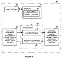
- FIG. 4 is a simplified block diagram showing EDA system 80 enabling the present invention.
- FIG. 1 is a flow chart of a computer-aided process for operating an electronic design automation system.
- user specification 11 of a prototype design is provided conventionally as an electronic file describing system or circuit structure (netlist) 24 and/or behavior (model) 10.
- simulation equation formulation 40 is performed automatically largely through software programs and flies using conventional computing equipment to modify model 10 according to the present invention described herein.
- a structural representation of model 10 is extracted such that the structural representation is constructed from a set of basic branch types (e.g., value probe, flow probe, value source, or flow source).
- an interconnection equation 42 e.g., flow probing 44, value probing 46, flow sources 48, or value sources 20
- equation formulation 40 conventional simulation 26 is performed on the formulated equations to determine 64 whether the prototype design is acceptable 30 or whether modification 62 is appropriate.
- a flow chart illustrates additional detail in the process of equation formulation 40, which occurs upon receiving behavioral model 10, provided preferably according to an analog hardware description language (AHDL).
- model 10 which defines conventional constitutive elements and/or interconnective relationships, is identified or interpreted as pre-defined structural representations.
- a structural representation of model 10 is generated or constructed from a set of basic component or branch types, including a value probe, a flow probe, a value source, and a flow source.
- a set of constitutive equations 52 (54-60) is generated or constructed, preferably in a form compatible with an underlying simulator.
- an part of interpreting model 10 for structural representation it is determined whether to provide automatically in model 10 an interconnect equation 42 for coupling to a pair of nodes included therein.
- model 10 interpretation 12 in performed in equation formulation 40 the generated structural representation is analyzed for every basic component or branch type 14, i.e., until analysis is done 27, at which point netlist 24 and the modified model 10 is simulated 26 and verified 30.
- each identified basic component determines 16 for each identified basic component whether ouch basic component represents a value source (e.g., a voltage source) or a flow probe (e.g., a current probe). If it is determined that the identified basic component represents a value source or a flow probe, then an interconnection equation 42 is generated 18, preferably corresponding particularly to the basic component or branch type (e.g., flow probing 44, value probing 46, flow sources 48, value sources 50). Then, after interconnection equation 42 is generated, it is determined 20 whether an other flow probe or value source is coupled to a pair of nodes in the structural representation.
- a value source e.g., a voltage source
- a flow probe e.g., a current probe
- model 10 is modified 36 to couple the interconnection equation to the pair of nodes, Alternately, if it is determined that the other flow probe or value source is coupled thereto, then model 10 is modified 22 to couple serially the interconnection equation to the other flow probe or value source. Also, if it ii determined that the identified basic component does not represent a value source or a flow probe, then it is determined 32 whether an other flow source 76 or value probe 74 is coupled to the pair of nodes 70, 72 of the structural representation, as shown schematically in FIG. 3.
- model 10 is modified 20 to couple the interconnection equation to nodes 70, 72. Alternately, if it is determined that the other flow source 76 or value probe 74 is coupled to nodes 70, 72, then model 10 is modified 34 to couple in parallel the interconnection equation to the other flow source 76 or value probe 74,
- FIG. 4 a block diagram is shown of electronic design automation (EDA) system 80 for implementing the present invention.
- System 80 includes conventional processor 02 and storage 84, which runs conventional EDA tools 86 for prototype system definition (e.g., netlisting/modeling) and verification (e.g., simulation).
- EDA tools 86 for prototype system definition (e.g., netlisting/modeling) and verification (e.g., simulation).
- the present invention generally resides in providing in conjunction with EDA tools 86 a behavioral-model software translator or modifier 88, for converting a high-level behavioral model 90, which in independent of the underlying simulator's equation formulation method, to a low-level behavioral model 92, which is dependent on the underlying simulator's equation formulation method, essentially by adding certain interconnection equations 84 into the model.
- low-level behavioral model 92 may be converted to high-level behavioral model, essentially by identifying and removing such added interconnection equations.
Landscapes
- Engineering & Computer Science (AREA)
- Computer Hardware Design (AREA)
- Physics & Mathematics (AREA)
- Theoretical Computer Science (AREA)
- Microelectronics & Electronic Packaging (AREA)
- Evolutionary Computation (AREA)
- Geometry (AREA)
- General Engineering & Computer Science (AREA)
- General Physics & Mathematics (AREA)
- Design And Manufacture Of Integrated Circuits (AREA)
- Management, Administration, Business Operations System, And Electronic Commerce (AREA)
- Tests Of Electronic Circuits (AREA)
Applications Claiming Priority (2)
| Application Number | Priority Date | Filing Date | Title |
|---|---|---|---|
| US13784293A | 1993-10-15 | 1993-10-15 | |
| US137842 | 1993-10-15 |
Publications (2)
| Publication Number | Publication Date |
|---|---|
| EP0660268A2 true EP0660268A2 (de) | 1995-06-28 |
| EP0660268A3 EP0660268A3 (de) | 1996-01-31 |
Family
ID=22479276
Family Applications (1)
| Application Number | Title | Priority Date | Filing Date |
|---|---|---|---|
| EP94105868A Withdrawn EP0660268A3 (de) | 1993-10-15 | 1994-04-15 | Verfahren zur Darstellung eines elektronischen Modells. |
Country Status (2)
| Country | Link |
|---|---|
| US (1) | US5634115A (de) |
| EP (1) | EP0660268A3 (de) |
Families Citing this family (15)
| Publication number | Priority date | Publication date | Assignee | Title |
|---|---|---|---|---|
| US5812431A (en) * | 1994-06-13 | 1998-09-22 | Cadence Design Systems, Inc. | Method and apparatus for a simplified system simulation description |
| US5896300A (en) | 1996-08-30 | 1999-04-20 | Avant| Corporation | Methods, apparatus and computer program products for performing post-layout verification of microelectronic circuits by filtering timing error bounds for layout critical nets |
| US6152612A (en) * | 1997-06-09 | 2000-11-28 | Synopsys, Inc. | System and method for system level and circuit level modeling and design simulation using C++ |
| US5949993A (en) * | 1997-10-31 | 1999-09-07 | Production Languages Corporation | Method for the generation of ISA simulators and assemblers from a machine description |
| US6009252A (en) * | 1998-03-05 | 1999-12-28 | Avant! Corporation | Methods, apparatus and computer program products for determining equivalencies between integrated circuit schematics and layouts using color symmetrizing matrices |
| US6314552B1 (en) | 1998-05-18 | 2001-11-06 | Lev A. Markov | Electronic design creation through architectural exploration |
| US6305006B1 (en) | 1998-05-18 | 2001-10-16 | Mentor Graphics Corporation | Generating candidate architectures for an architectural exploration based electronic design creation process |
| US6917909B1 (en) | 1998-05-18 | 2005-07-12 | Lev A. Markov | Facilitating guidance provision for an architectural exploration based design creation process |
| US6101323A (en) | 1998-07-15 | 2000-08-08 | Antrim Design Systems, Inc. | Method and apparatus for improvement of sparse matrix evaluation performance |
| WO2000057317A1 (en) * | 1999-03-19 | 2000-09-28 | Moscape, Inc. | System and method for performing assertion-based analysis of circuit designs |
| US7672827B1 (en) | 2000-08-28 | 2010-03-02 | Cadence Design Systems, Inc. | Method and system for simulation of analog/digital interfaces with analog tri-state ioputs |
| US7302670B2 (en) * | 2000-12-21 | 2007-11-27 | Bryan Darrell Bowyer | Interactive interface resource allocation in a behavioral synthesis tool |
| US7310787B2 (en) * | 2002-03-08 | 2007-12-18 | Shiv Prakash | Array transformation in a behavioral synthesis tool |
| US7783467B2 (en) * | 2005-12-10 | 2010-08-24 | Electronics And Telecommunications Research Institute | Method for digital system modeling by using higher software simulator |
| US7735050B2 (en) * | 2006-02-09 | 2010-06-08 | Henry Yu | Managing and controlling the use of hardware resources on integrated circuits |
Family Cites Families (3)
| Publication number | Priority date | Publication date | Assignee | Title |
|---|---|---|---|---|
| US5047971A (en) * | 1987-06-23 | 1991-09-10 | Intergraph Corporation | Circuit simulation |
| EP0490478A2 (de) * | 1990-12-14 | 1992-06-17 | Tektronix Inc. | Automatische Kompilierung von Modellgleichungen in einem gradientbasierten Analogsimulator |
| US5469366A (en) * | 1993-09-20 | 1995-11-21 | Lsi Logic Corporation | Method and apparatus for determining the performance of nets of an integrated circuit design on a semiconductor design automation system |
-
1994
- 1994-04-15 EP EP94105868A patent/EP0660268A3/de not_active Withdrawn
- 1994-12-13 US US08/355,058 patent/US5634115A/en not_active Expired - Lifetime
Also Published As
| Publication number | Publication date |
|---|---|
| US5634115A (en) | 1997-05-27 |
| EP0660268A3 (de) | 1996-01-31 |
Similar Documents
| Publication | Publication Date | Title |
|---|---|---|
| US7299155B2 (en) | Method and apparatus for decomposing and verifying configurable hardware | |
| EP0508075B1 (de) | Automatische Logikmodell-Erzeugung aus einer Schaltschema-Datenbank | |
| US6083269A (en) | Digital integrated circuit design system and methodology with hardware | |
| EP0660268A2 (de) | Verfahren zur Darstellung eines elektronischen Modells | |
| EP0296812B1 (de) | Verfahren für einen Blockdiagramm-Simulator | |
| JP2862886B2 (ja) | Asic用計算機支援設計システム | |
| US5016204A (en) | Expert system for performing diagnostic and redesign operations incorporating multiple levels of simulation detail | |
| US8150673B1 (en) | Partitioning a model in modeling environments | |
| US8589870B2 (en) | System and method for transforming graphical models | |
| US5471398A (en) | MTOL software tool for converting an RTL behavioral model into layout information comprising bounding boxes and an associated interconnect netlist | |
| EP1093619B1 (de) | System und verfahren zum identifizieren von endlichen automaten und überprüfung des schaltkreisdesigns | |
| EP0676707B1 (de) | Ausdrucks-Propagierung für hierarchische Netzlisten | |
| EP0508620B1 (de) | Verfahren und System zur automatischen Bestimmung der logischen Funktion einer Schaltung | |
| US5974241A (en) | Test bench interface generator for tester compatible simulations | |
| US5949992A (en) | Method and apparatus for a simplified system simulation description | |
| US6421823B1 (en) | Bidirectional socket stimulus interface for a logic simulator | |
| Shanmugan et al. | Block-oriented systems simulator (BOSS) | |
| US7681156B2 (en) | Transmission circuit simulator and transmission circuit simulation program storage medium | |
| JP2551944B2 (ja) | 図的言語処理システム | |
| Jiang et al. | Automation of test case generation from textual use cases | |
| JP2773655B2 (ja) | Vhdlシミュレータ | |
| Bruchertseifer et al. | SMT Solvers–A PromisingWay for Verifying User Interfaces? | |
| Moser et al. | Generating VHDL-A-like models using ABSynth | |
| KR100316246B1 (ko) | 내장형 소프트웨어 시스템의 안전성 분석 방법 및 그 장치 | |
| GB2321118A (en) | Development of integrated circuits |
Legal Events
| Date | Code | Title | Description |
|---|---|---|---|
| PUAI | Public reference made under article 153(3) epc to a published international application that has entered the european phase |
Free format text: ORIGINAL CODE: 0009012 |
|
| AK | Designated contracting states |
Kind code of ref document: A2 Designated state(s): DE FR GB IT |
|
| PUAL | Search report despatched |
Free format text: ORIGINAL CODE: 0009013 |
|
| RHK1 | Main classification (correction) |
Ipc: G06F 17/50 |
|
| AK | Designated contracting states |
Kind code of ref document: A3 Designated state(s): DE FR GB IT |
|
| STAA | Information on the status of an ep patent application or granted ep patent |
Free format text: STATUS: THE APPLICATION IS DEEMED TO BE WITHDRAWN |
|
| 18D | Application deemed to be withdrawn |
Effective date: 19960801 |
|
| RIN1 | Information on inventor provided before grant (corrected) |
Inventor name: KUNDERT, KENNETH S. Inventor name: FITZPATRICK, DANIEL |