EP0660322A2 - Optischer Plattenspieler und Verarbeitungsverfahren zur Datenwiedergabe von dem optischen Plattenspieler - Google Patents
Optischer Plattenspieler und Verarbeitungsverfahren zur Datenwiedergabe von dem optischen Plattenspieler Download PDFInfo
- Publication number
- EP0660322A2 EP0660322A2 EP94402987A EP94402987A EP0660322A2 EP 0660322 A2 EP0660322 A2 EP 0660322A2 EP 94402987 A EP94402987 A EP 94402987A EP 94402987 A EP94402987 A EP 94402987A EP 0660322 A2 EP0660322 A2 EP 0660322A2
- Authority
- EP
- European Patent Office
- Prior art keywords
- subcode
- reproduction data
- signal
- reproduction
- output
- Prior art date
- Legal status (The legal status is an assumption and is not a legal conclusion. Google has not performed a legal analysis and makes no representation as to the accuracy of the status listed.)
- Granted
Links
Images


Classifications
-
- G—PHYSICS
- G11—INFORMATION STORAGE
- G11B—INFORMATION STORAGE BASED ON RELATIVE MOVEMENT BETWEEN RECORD CARRIER AND TRANSDUCER
- G11B20/00—Signal processing not specific to the method of recording or reproducing; Circuits therefor
- G11B20/10—Digital recording or reproducing
-
- G—PHYSICS
- G11—INFORMATION STORAGE
- G11B—INFORMATION STORAGE BASED ON RELATIVE MOVEMENT BETWEEN RECORD CARRIER AND TRANSDUCER
- G11B27/00—Editing; Indexing; Addressing; Timing or synchronising; Monitoring; Measuring tape travel
- G11B27/10—Indexing; Addressing; Timing or synchronising; Measuring tape travel
- G11B27/19—Indexing; Addressing; Timing or synchronising; Measuring tape travel by using information detectable on the record carrier
- G11B27/28—Indexing; Addressing; Timing or synchronising; Measuring tape travel by using information detectable on the record carrier by using information signals recorded by the same method as the main recording
- G11B27/30—Indexing; Addressing; Timing or synchronising; Measuring tape travel by using information detectable on the record carrier by using information signals recorded by the same method as the main recording on the same track as the main recording
- G11B27/3027—Indexing; Addressing; Timing or synchronising; Measuring tape travel by using information detectable on the record carrier by using information signals recorded by the same method as the main recording on the same track as the main recording used signal is digitally coded
- G11B27/3063—Subcodes
-
- G—PHYSICS
- G11—INFORMATION STORAGE
- G11B—INFORMATION STORAGE BASED ON RELATIVE MOVEMENT BETWEEN RECORD CARRIER AND TRANSDUCER
- G11B20/00—Signal processing not specific to the method of recording or reproducing; Circuits therefor
- G11B20/10—Digital recording or reproducing
- G11B20/10527—Audio or video recording; Data buffering arrangements
-
- G—PHYSICS
- G11—INFORMATION STORAGE
- G11B—INFORMATION STORAGE BASED ON RELATIVE MOVEMENT BETWEEN RECORD CARRIER AND TRANSDUCER
- G11B20/00—Signal processing not specific to the method of recording or reproducing; Circuits therefor
- G11B20/10—Digital recording or reproducing
- G11B20/14—Digital recording or reproducing using self-clocking codes
- G11B20/1403—Digital recording or reproducing using self-clocking codes characterised by the use of two levels
-
- G—PHYSICS
- G11—INFORMATION STORAGE
- G11B—INFORMATION STORAGE BASED ON RELATIVE MOVEMENT BETWEEN RECORD CARRIER AND TRANSDUCER
- G11B2220/00—Record carriers by type
- G11B2220/20—Disc-shaped record carriers
- G11B2220/21—Disc-shaped record carriers characterised in that the disc is of read-only, rewritable, or recordable type
- G11B2220/213—Read-only discs
-
- G—PHYSICS
- G11—INFORMATION STORAGE
- G11B—INFORMATION STORAGE BASED ON RELATIVE MOVEMENT BETWEEN RECORD CARRIER AND TRANSDUCER
- G11B2220/00—Record carriers by type
- G11B2220/20—Disc-shaped record carriers
- G11B2220/25—Disc-shaped record carriers characterised in that the disc is based on a specific recording technology
- G11B2220/2525—Magneto-optical [MO] discs
- G11B2220/2529—Mini-discs
-
- G—PHYSICS
- G11—INFORMATION STORAGE
- G11B—INFORMATION STORAGE BASED ON RELATIVE MOVEMENT BETWEEN RECORD CARRIER AND TRANSDUCER
- G11B2220/00—Record carriers by type
- G11B2220/20—Disc-shaped record carriers
- G11B2220/25—Disc-shaped record carriers characterised in that the disc is based on a specific recording technology
- G11B2220/2537—Optical discs
- G11B2220/2545—CDs
-
- G—PHYSICS
- G11—INFORMATION STORAGE
- G11B—INFORMATION STORAGE BASED ON RELATIVE MOVEMENT BETWEEN RECORD CARRIER AND TRANSDUCER
- G11B7/00—Recording or reproducing by optical means, e.g. recording using a thermal beam of optical radiation by modifying optical properties or the physical structure, reproducing using an optical beam at lower power by sensing optical properties; Record carriers therefor
- G11B7/08—Disposition or mounting of heads or light sources relatively to record carriers
- G11B7/09—Disposition or mounting of heads or light sources relatively to record carriers with provision for moving the light beam or focus plane for the purpose of maintaining alignment of the light beam relative to the record carrier during transducing operation, e.g. to compensate for surface irregularities of the latter or for track following
- G11B7/0946—Disposition or mounting of heads or light sources relatively to record carriers with provision for moving the light beam or focus plane for the purpose of maintaining alignment of the light beam relative to the record carrier during transducing operation, e.g. to compensate for surface irregularities of the latter or for track following specially adapted for operation during external perturbations not related to the carrier or servo beam, e.g. vibration
Definitions
- the present invention relates to a disc player for reproducing a digital audio disc called a compact disc (CD) or a mini disc (MD) and reproducing an information-recorded disc such as a CD-ROM disc (the discs are hereinafter generically referred to simply as discs) and, more particularly, to a disc player having a constitution in which reproduction data read from a disc are stored in a large-capacity memory to be read for output, and to a method of processing the reproduction data.
- CD digital audio disc
- MD mini disc
- CD-ROM disc the discs are hereinafter generically referred to simply as discs
- a disc player having a constitution in which reproduction data read from a disc are stored in a large-capacity memory to be read for output, and to a method of processing the reproduction data.
- Some disc players such as a CD player have an anti-shock constitution for preventing, by assuring continuity of PCM (Pulse Code Modulation) data, a so-called sound skip from occurring when a so-called track jump caused by an external disturbance such as an undue vibration or shock is applied to the player during a disc playback operation.
- PCM Pulse Code Modulation
- track jump denotes that an information reading light spot projected from an optical pick-up for reading recorded information by tracing a record track (a pit train) on a disc jumps off over a track or tracks.
- a data rate of reproducing data from a disc is substantially the same as a data rate of ultimate audio output.
- a disc rotates at a speed, for example, about twice as high as a speed of disc rotation in the ordinary disc player, thereby reading recorded PCM data at an accordingly higher speed than a data reading speed of the ordinary disc player.
- the PCM data thus read are temporarily stored in a large-capacity DRAM (Dynamic Random Access Memory) and are read from the DRAM at the reproducing data rate of the ordinary disc player for output.
- DRAM Dynamic Random Access Memory
- the information reading light spot of the pick-up is returned to a position immediately before a position at which the track jump occurred, restarting reproduction from the former position.
- the PCM data is established based on a subcode synchronizing signal having wow caused by a spindle-drive motor, a data determination signal comes to have wow, making it uncertain where in a one subcode frame the data is established. Consequently, it is required to set a window for one frame jitter margin in which the PCM data coming from the disc is compared with the PCM data coming from the DRAM for a match to perform sound linking processing on the PCM data.
- a disc player constituted so that reproduction data read from a disc are temporarily stored in a large-capacity memory and then read from the memory for output.
- the disc player according to the invention comprises a jitter detector for detecting an amount of jitter in a second clock synchronized with the reproduction data as opposed to a first clock having a fixed frequency, a counter for counting the second clock for 98 frames, an adder/ subtractor for adding or subtracting the amount of jitter to or from an output of the counter, and an offset circuit for providing an offset for a predetermined number of frames to an output of the adder/subtractor, wherein the reproduction data are written to the large-capacity memory based on an output of the offset circuit.
- a disc player comprising a match detector for detecting a match, a predetermined number of times consecutively, between a subcode synchronizing signal obtained from the reproduced data (hereinafter referred to as a reproduction subcode synchronizing signal) and the output of the counter and an output determination circuit for making valid the output of the offset circuit only when the match is detected by the match detector.
- a disc player constituted so that the reproduction data read from the disc are temporarily stored in the large-capacity memory and then read from the memory for output, the disc player having a memory for reproduction data time information corresponding to the reproduction data to be written to the mass memory.
- a disc player constituted so that the reproduction data time information is stored in the above-mentioned memory in a thinned out manner.
- a reproduction data processing method for generating a subcode synchronizing signal synchronized with a clock having a fixed frequency, reading time information of a subcode contained in the reproduction data in synchronization with a reproduction subcode synchronizing signal obtained from the reproduction data to detect a sound overleap based on the time information and a last valid (determined/established) address in the large-capacity memory, and, if no sound overleap has been detected, determining the reproduction data to be stored in the large-capacity memory based on the subcode synchronizing signal, in a disc player constituted to write the reproduction data coming from a disc to the large-capacity memory and then read the data from the large-capacity memory for output.
- a reproduction data processing method for accessing the last valid address if the sound overleap has been detected in the above-mentioned reproduction data processing method, reading the time information of the subcode in synchronization with the reproduction subcode synchronizing signal to compare the time information of the subcode with data relating to the last valid address, and, if a match is found between the time information of the subcode and the data relating to the last valid address, writing the reproduction data to the large-capacity memory based on the subcode synchronizing signal.
- an amount of jitter in a reproduction clock relative to a fixed clock is detected, the obtained jitter amount is added to or subtracted from a count output obtained by counting the reproduction clock by the number of times for 98 frames, and an offset of a predetermined number of frames is applied to the result of the addition or subtraction to generate a subcode synchronizing signal synchronized with the fixed clock.
- the reproduction data is written to the large-capacity memory, thereby implementing data determination by time axis and sound linking on time axis.
- the reproduction subcode synchronizing signal coming from the disc is compared with the count output of the fixed clock to make valid the generated subcode synchronizing signal only when a match has been found a predetermined number of times consecutively, thereby eliminating a false reproduction subcode synchronizing signal caused by a scratch or the like on the disc to discriminate a true reproduction subcode synchronizing signal.
- the subcode synchronizing signal can be generated without being affected by a scratch or the like on the disc.
- the time information of the reproduction data to be written to the large-capacity memory is stored in the memory provided to store the time information, thereby providing the time information of the reproduction data. Consequently, it is unnecessary to perform processing of time conversion while monitoring a storage amount of the large-capacity memory, which is required conventionally, thereby mitigating a software load of a microcomputer used in the system and implementing real-time display of the time information.
- the time information is stored in the memory in a thinned out manner.
- addresses of the memory are made common with upper addresses of the large-capacity memory to link the reproduction data with its time information.
- This set-up provides the time information of the reproduction data with a minimum memory capacity.
- the subcode synchronizing signal synchronized with the fixed clock is generated and, if no sound overleap has been detected, the generated subcode synchronizing signal is used to establish reproduction data to be stored in the large-capacity memory.
- reproduction data processing method if a sound overleap occurs, writing of the reproduction data to the large-capacity memory starts based on the generated subcode synchronizing signal, thereby implementing sound linking on the time axis. Consequently, if reproduction data at a sound linking point is processed with previous-value hold or interpolation, sounds can be linked without error. Also, in software in which fixed patterns continue, sounds can be linked correctly.
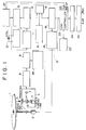
- FIG. 1 there is shown a block diagram illustrating a constitution of a control system of a CD player practiced as one preferred embodiment of the invention.
- a disc (CD) 1 is driven in rotation by a spindle-drive motor 2.
- Information recorded on the disc is read with an optical pick-up 3 (hereinafter referred to simply as a pick-up).
- the pick-up 3 comprises a laser diode 4, an objective lens 5 for focusing a laser beam coming from the laser diode 4 onto a signal recorded side of the disc 1 as an information reading light spot, a polarized beam splitter 6 for changing a direction in which a reflected light beam coming from the disc 1 goes, and a photo detector 7 for receiving the reflected light beam.
- the pick-up 3 is moved in the radial direction of the disc 1 by a thread feed motor, not shown.
- the pick-up 3 further contains a tracking actuator, not shown, for deflecting the information reading light spot in the disc radial direction relative to a record track provided on the disc 1 and a focus actuator, not shown, for moving the objective lens 5 in its optical axis direction.
- An output signal of the pick-up 3 is converted by an I(current)/V(voltage) amplifier 8 from current signal to a voltage signal.
- the resultant voltage signal is shaped by an RF equalizer 9 to be fed to a DSP (Digital Signal Processor) circuit 10.
- DSP Digital Signal Processor
- Signal processing is performed in the DSP circuit 10 is performed as follows. First, asymmetry correction is performed in a PLL (Phase Locked Loop) asymmetry correction circuit 11 to provide a binary signal. Based on an edge of the binary signal, continuous reproduction clock signals are generated according to a constitution of the PLL.
- PLL Phase Locked Loop
- the term "asymmetry” herein denotes a state in which the center of an eye pattern of an RF signal deviates from the center of oscillation.
- EFM Eight-to-Fourteen Modulation
- SCOR subcode synchronizing signal
- the PCM data after EFM demodulation is stored in a RAM (Random Access Memory) 14 once, error-corrected in an error correction circuit 15 based on an error correction and detection parity, and deinterleaved of CIRC (Cross Interleave Reed-Solomon Code) in a deinterleave circuit 16.
- the DSP circuit 10 contains a clock generator 17 for generating a system clock signal based on an output of a crystal resonator 21 and performs signal processing based on the generated system clock.
- a reproduction clock signal generated in the PLL asymmetry correction circuit 11 as a write clock signal WFCK is used, and the above-mentioned system clock signal is used as a read clock signal RFCK.
- the PCM data passed through the DSP circuit 10 is stored in a large-capacity DRAM 23 via an ESP (Electric Shock Proof) controller 22.
- the PCM data stored in the DRAM 23 is read through the ESP controller 22.
- the read PCM data is then filtered by a digital filter 24, converted by a D/A converter 25 to analog data, and outputted as L-channel and R-channel audio outputs.
- the DRAM 23 is used to assure continuity of the PCM data to prevent sound overleap from occurring when a track jump has taken place due to an external disturbance such as an undue shock during playback.
- the microcomputer returns the information reading light spot of the pick-up 3 to a position at which the spot was projected immediately before the occurrence of the track jump to restart the reproduction, while the ESP controller 22 links the PCM data to be obtained after the restart of the reproduction with the PCM data stored in the DRAM 23 that was present immediately before the occurrence of the track jump.
- a specific constitution and function of the ESP controller 22 will be described later in more detail.
- the DSP circuit 10 is provided with a spindle servo signal processing circuit 18 for controlling the rotation of the spindle-drive motor 2 based on a phase difference between a reference clock signal and the reproduction clock signal.
- An optical- system servo signal processing circuit 26 controls servo systems associated with operation of the pick-up 3: that is, a tracking servo system for making the information light spot follow the track on the disc 1; a focus servo system for keeping the light spot always focused on the signal recorded surface of the disc 1; and a thread servo system for controlling the position of the pick-up 3 in the radial direction of the disc 1.
- the spindle servo signal processing circuit 18 drives, normally in a low-speed mode, the spindle-drive motor 2 for rotating the disc 1, and when a track jump occurs, drives the spindle-drive motor 2 in a high-speed mode.
- the spindle servo signal processing circuit 18 drives the spindle-drive motor 2 in the low speed mode again.
- the spindle-drive motor 2 is driven at a normal rotational speed of a CD player (or a normal speed).
- the spindle-drive motor 2 is driven at a speed twice as high for example.
- the ESP controller 22 controls PCM data read/write operations on the DRAM 23. Addresses for accessing data stored in the DRAM 23 include a data read address RA and a data write address WA.
- the data read address RA is incremented based on a clock signal generated inside the ESP controller 22, while the data write address WA is incremented based on a clock signal outputted from the DSP circuit 10.
- PCM data written to the DRAM 23 based on the clock signal coming from the DSP circuit is not always correct. Therefore, it is required to check a subcode or the like of the PCM data for a sound overleap.
- the microcomputer 20 checks a Q channel (hereinafter referred to as a subcode Q) of a subcode supplied from the subcode processing circuit 13 of the DSP circuit 10 for a sound overleap caused by a track jump due to external disturbance such as a shock or a vibration.
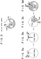
- the ESP controller Upon receiving an output from the microcomputer 20 indicating detection of no sound overleap, the ESP controller updates a last address of the PCM data written to the DRAM 23 as a valid (or established) address VWA. Namely, referring to Fig. 2, an area between the valid address VWA and the read address RA is a data area having no sound overleap. The data in this area is handled as valid data.
- Fig. 3 there is shown a relationship between the read address RA, the write address WA, and the valid address VWA in the DRAM 23.
- the write address WA advances starting from an initial state of Fig. 3 (a) twice as fast as the read address RA, data is written by the write address WA, registered by the valid address VWA, and sequentially read by the read address RA (Fig. 3 (b)).
- the write address WA eventually catches up the read address RA by passing a state of Fig. 3(c).
- the write operation is disabled (Fig. 3 (d)).
- the ESP controller goes back to the last valid address.
- the microcomputer 20 returns the pick-up 3 to the position immediately before the position at which the track jump has occurred to restart the reproduction from that position and, at the same time, reads the subcode Q at the rising of the reproduction subcode synchronizing signal SCOR to compare the subcode Q with data relating to the last valid address, the latter data being held in the microcomputer itself. Then, if a match is found between the compared data, the ESP controller 22 restarts the writing in the DRAM 23 when a subcode synchronizing signal GRSCOR, to be generated within 2.45 ms to 6.23 ms, is at HIGH level; the signal GRSCOR is to be described later.
- GRSCOR subcode synchronizing signal
- the ESP controller 22 is provided with a subcode synchronizing signal generator for generating the subcode synchronizing signal GRSCOR free of the wow caused by the spindle-drive motor 2.
- Fig. 4 shows an example of constitution of this subcode synchronizing signal generator.
- a jitter counter 28 measures a jitter amount of the write clock signal WFCK or the reproduction clock signal coming from the disc 1 as opposed to the read clock signal RFCK or the fixed clock signal.
- a reference counter 29 counts the cycles of the write clock signal WFCK for 98 frames.
- a count output of the reference counter 29 is added to or subtracted from the jitter amount measured by the jitter counter 28.
- an offset of 64 frames for example is given to the addition/subtraction output, by an offset circuit 31.
- subtracting (or adding) the measured jitter amount from the count output of the write clock WFCK for 98 frames, and applying a correction in time axis to the reproduction subcode synchronizing signal SCOR containing the wow caused by the spindle-drive motor can eliminate the wow from the reproduction subcode synchronizing signal SCOR, thereby generating the subcode synchronizing signal GRSCOR synchronized with the PCM data read from the DRAM 23 based on the read clock RFCK having a crystal resonator precision.
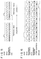
- a match detector 33 detects a match between the reproduction subcode synchronizing signal SCOR coming from the DSP circuit 10 and the count output of the reference counter 29. If the match is found twice consecutively for example as shown in Fig. 5, the match detector 33 sends a match detect signal GSS to an output determination circuit 32 and is locked. Upon reception of the match detect signal GSS, or when the match between the reproduction subcode synchronizing signal SCOR and the count output of the reference counter has been found twice consecutively, the output determination circuit 32 outputs the generated subcode synchronizing signal GRSCOR.
- the match detector 33 is locked, the match detector is thereafter kept locked until a reset signal comes from the microcomputer 20 or a signal GTOP to be outputted when a frame sync signal is resynchronized by the DSP circuit 10 goes HIGH level. While the match detector 33 is locked, subcode synchronizing signal GRSCOR is kept outputted. When the RAM 14 of the DSP circuit 10 overflows, the ESP controller 22 once resets the read clock RFCK and the measured jitter amount of the write clock WFCK to perform the measurement again.
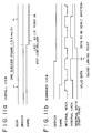
- Fig. 6 shows a timing chart obtained when a frame jitter margin (FJM) is ⁇ 0 in a subcode synchronizing signal generator having the above-mentioned constitution.
- FJM frame jitter margin
- the reference counter 29 counts 98 frames because the reproduction subcode synchronizing signal (SCOR) has a pulse every 98 frames. Obviously, in a system where the reproduction subcode synchronizing signal had a pulse after a different number of frames, e.g. every N frames, the reference counter 29 would count N frames.
- the microcomputer 20 accesses a position immediately preceding the occurrence of a track jump, compares data regarding the last valid address of the DRAM 23 (this data being present at the microcomputer 20) with the subcode Q being read from the disc 1, and determines a point for sound linking. That is, the microcomputer 20 must determine whether to perform sound linking or not by reading the subcode Q at the rising of the reproduction subcode synchronizing signal SCOR and comparing the read subcode Q with the data regarding the last valid DRAM address.
- a time between the rising of the reproduction subcode synchronizing signal SCOR and the rising of the subcode synchronizing signal GRSCOR is a minimum of 2.45 ms and a maximum of 6.23 ms. Namely, in sound linking, it is most critical for the microcomputer 20 when the frame jitter margin is -28 frames. During this 2.45 ms, the microcomputer must read the subcode Q to compare it with the data relating to the last established address of the DRAM 23 to determine whether to perform sound linking or not.
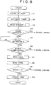
- step S1 Upon detection of the rising of the reproduction subcode synchronizing signal SCOR (step S1), the microcomputer 20 activates a built-in timer (step S2) and reads the subcode Q (step S3).
- the microcomputer compares a difference between the read subcode Q and the previously established address to determine whether a sound overleap has taken place or not (step S4). If the sound overleap has been detected, the microcomputer 20 passes control to a sound linking routine to be described later. If no sound overleap has been detected, the microcomputer 20 monitors the rising of the subcode synchronizing signal GRSCOR (step S5). Upon detection of the rising of the subcode synchronizing signal GRSCOR, the microcomputer 20 determines, based on a time measured by the above-mentioned timer, whether the subcode synchronizing signal GRSCOR has come between 2.45 ms and 6.23 ms (step S6).
- the microcomputer 20 passes control to the sound linking routine. If the GRSCOR has come during that period of time, then the microcomputer 20 sends a registration permit signal XQOK to the ESP controller 22 while the subcode synchronizing signal GRSCOR is HIGH (about 68 ( ⁇ s) (step S7)). When the registration permit signal XQOK has come to the ESP controller 22 while the subcode synchronizing signal GRSCOR is HIGH, the ESP controller 22 loads the write address WA in the valid address VWA to establish the data. It should be noted here that a point to be established by the ESP controller is always fixed within one subcode frame as shown in Fig. 10.
- the microcomputer 20 then sends a confirmation request signal XSOE to the ESP controller 22 to confirm whether the registration has been made correctly (step S8).
- the ESP controller 22 returns a registration complete signal QRCVD of HIGH level in response to the XSOE signal.
- the microcomputer 20 waits for the return of the QRCVD signal from the ESP controller 22 (step S9). If the QRCVD is not HIGH, the microcomputer 20 passes control to the sound linking routine. If the QRCVD is HIGH, the microcomputer 20 updates the valid address VWA (step S10), thereby ending the series of processing operations for the data establishment.
- a write enable signal, XWRE when at a LOW level enables the writing of data to the DRAM 23.
- the microcomputer 20 makes HIGH the write enable signal XWRE, thereby disabling the writing (step S11).
- the microcomputer 20 accesses the final valid address VWA it holds (step S12) and sends a SCOR resynchronizing signal GRSRST to the ESP controller 22 (step S13).
- the match detector 33 of the subcode synchronizing signal generator (Fig. 4) is reset by the SCOR resynchronizing signal GRSRST.
- step S14 upon detection of the rising of the reproduction subcode synchronizing signal SCOR (step S14), the microcomputer 20 activates the incorporated timer (step S15) to read the subcode Q (step S16). Then, the microcomputer 20 determines whether the subcode Q matches the final valid address VWA (step S17). If no match is found, the microcomputer returns to step S14 to repeat the above-mentioned processing operations.
- the microcomputer 20 monitors the rising of the subcode synchronizing signal GRSCOR (step S18). Upon detection of the rising of the subcode synchronizing signal GRSCOR, the microcomputer 20 determines, based on the time measured by the timer, whether the subcode synchronizing signal GRSCOR has come within a period of time between 2.45 ms and 6.23 ms (step S19). If the subcode synchronizing signal GRSCOR has not come within the period of time between 2.45 ms and 6.23 ms, the microcomputer returns to step S12 to repeat the above-mentioned processing operations.
- the microcomputer 20 makes LOW the above-mentioned write enable signal XWRE while the subcode synchronizing signal GRSCOR is HIGH, thereby permitting the ESP controller to write the data to the DRAM 23 (step S20).
- This causes the ESP controller 22 to start writing the PCM data read from the disc 1 to the DRAM 23 when the established point of the subcode frame has been reached as shown in Fig. 11.
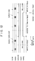
- Fig. 12 shows a timing chart describing the series of operations ranging from the detection of sound overleap to the sound linking.
- the ESP controller 22 incorporates a RAM 27 dedicated to the subcode Q as shown in Fig. 1.
- This RAM is provided to store the time information of reproduction data.
- the time information to be stored in the RAM 27 are thinned out to some extent in the present embodiment. In what follows, the thinning out will be described on the supposition that the external DRAM 23 has a storage capacity of 16M (i.e. 16 x 220) bits.
- linking PCM data with its time information by making the upper address of the external DRAM 23 common with the address of the incorporated RAM 27 allows the microcomputer 20 to correct the subcode Q in time axis by means of two operations; sending the time information of the PCM data being read from the disc 1 to the ESP controller 22 and reading the time information from the ESP controller 22.
- the microcomputer 20 performs the time information conversion while monitoring the storage capacity of the DRAM 23 for displaying resultant data, thereby increasing the load of the microcomputer 20.
- the writing of the subcode Q to the incorporated RAM is performed while a write enable signal MWE is HIGH (13.3 ms/2) as shown in Fig. 13.
- the one-byte data TNO, IND, MIN, and SEC are put on serial I/F data, clock, and latch to be written in four time intervals with the least significant bit (LSB) first.
- the reading of the subcode Q from the RAM 27 is performed while the read enable signal MRE is HIGH (13.3 ms/2) as shown in Fig. 14.
- a LOW level pulse is sent 32 times as a read clock QRCK to read the TNO, IND, MIN, and SEC from a subcode Q output terminal QTBC with the LSB first.
- the present invention has been described as applied to a CD player. It will be apparent to those skilled in the art that the present invention is not restricted to the CD player; instead, the present invention is applicable to other type of disc players such as those for reproducing an MD or a CD-ROM disc.
- an amount of jitter contained in a write clock synchronized with a reproduction clock as opposed to a read clock synchronized with a fixed clock is detected, the detected jitter amount is added to or subtracted from a count output obtained by counting the write clock for 98 frames and an offset for the predetermined number of frames is given to an addition/subtraction result to generate a subcode synchronizing signal completely synchronized with the read clock, based on which subcode synchronizing signal reproduction data is written to a large-capacity memory.
- This constitution implements data establishment on the time axis and sound linking on the time axis, so that, if the reproduction data at a sound linking point is processed with previous-value hold or interpolation, the sound linking can be performed without error and, in software having successive fixed patterns, correct sound linking is assured.
- a reproduction subcode synchronizing signal read from a disc is compared with a count output of a write clock and, only when a match is found by the predetermined number of times successively, a generated subcode synchronized signal is made valid.
- This constitution eliminates a false reproduction subcode synchronizing signal caused by a scratch or the like on the disc and determines a true reproduction subcode synchronizing signal, thereby enabling to generate the subcode synchronizing signal without being affected by the scratch or the like on the disc.
- time information of reproduction data to be written to a large-capacity memory is stored in a memory for storing the time information.
- the stored time information makes it unnecessary to a time converting operation while monitoring the storage capacity of the large-capacity memory, thereby mitigating the load placed on microcomputer software and permitting the display of the time information in real-time.
- the time information is stored in the memory for storing the time information in a thinned-out manner to restrict a capacity of this memory to a minimum, thereby providing the time information of reproduction data at a relatively low cost.
- a subcode synchronizing signal synchronized with a read clock is generated. Therefore, if no sound overleap has occurred, the generated subcode synchronizing signal is used to establish reproduction data to be stored in the large-scale memory, thereby permitting data establishment by time axis. Further, according to the invention, if a sound overleap has occurred, writing of the reproduction data to the large-capacity memory is started on the basis of the generated subcode synchronizing signal, thereby implementing sound linking on the time axis. Consequently, even if the reproduction data at a sound linking point is processed with previous-value hold or interpolation, the sound linking can be performed without involving an error and, in software having fixed patterns successively, sounds can be linked correctly.
Landscapes
- Engineering & Computer Science (AREA)
- Signal Processing (AREA)
- Multimedia (AREA)
- Signal Processing For Digital Recording And Reproducing (AREA)
Applications Claiming Priority (3)
| Application Number | Priority Date | Filing Date | Title |
|---|---|---|---|
| JP346575/93 | 1993-12-22 | ||
| JP34657593A JP3321950B2 (ja) | 1993-12-22 | 1993-12-22 | ディスクプレーヤおよびその再生データの処理方法 |
| JP34657593 | 1993-12-22 |
Publications (3)
| Publication Number | Publication Date |
|---|---|
| EP0660322A2 true EP0660322A2 (de) | 1995-06-28 |
| EP0660322A3 EP0660322A3 (de) | 1996-12-04 |
| EP0660322B1 EP0660322B1 (de) | 2003-03-26 |
Family
ID=18384354
Family Applications (1)
| Application Number | Title | Priority Date | Filing Date |
|---|---|---|---|
| EP94402987A Expired - Lifetime EP0660322B1 (de) | 1993-12-22 | 1994-12-22 | Optischer Plattenspieler und Verarbeitungsverfahren zur Datenwiedergabe von dem optischen Plattenspieler |
Country Status (6)
| Country | Link |
|---|---|
| US (1) | US5508983A (de) |
| EP (1) | EP0660322B1 (de) |
| JP (1) | JP3321950B2 (de) |
| KR (1) | KR100284447B1 (de) |
| CN (1) | CN1096059C (de) |
| DE (1) | DE69432343T2 (de) |
Cited By (2)
| Publication number | Priority date | Publication date | Assignee | Title |
|---|---|---|---|---|
| FR2768841A1 (fr) * | 1997-09-23 | 1999-03-26 | United Microelectronics Corp | Systeme de lecteur de disque compact avec possibilite de reproduction ininterrompue en presence de vibrations, et procede de reproduction correspondant |
| NL1007870C2 (nl) * | 1997-12-23 | 1999-06-30 | United Microelectronics Corp | Compact disc-spelersysteem met een voor trilling ongevoelig vermogen tot ononderbroken afspelen. |
Families Citing this family (20)
| Publication number | Priority date | Publication date | Assignee | Title |
|---|---|---|---|---|
| US5818801A (en) * | 1995-06-30 | 1998-10-06 | Sanyo Electric Co., Ltd. | Shockproof optical reproduction device |
| KR0180307B1 (ko) * | 1995-10-06 | 1999-04-15 | 김광호 | 멀티 배속 광디스크 재생장치의 스핀들 서보회로 |
| US6064634A (en) * | 1997-08-18 | 2000-05-16 | Stmicroelectronics, N.V. | Compact disc player capable of automatically generating a start command |
| US6131138A (en) * | 1997-08-18 | 2000-10-10 | Stmicroelectronics N.V. | Variable speed compact disc drive including an elastic buffer |
| US6229769B1 (en) | 1997-08-18 | 2001-05-08 | Stmicroelectronics N.V. | Methods and apparatus for delayed block release in compact disc systems |
| US6058453A (en) * | 1997-08-18 | 2000-05-02 | Stmicroelectronics, Inc. | Method and apparatus for subcode/data synchronization in a compact disc system |
| US6442329B1 (en) * | 1998-02-28 | 2002-08-27 | Michael L. Gough | Method and apparatus for traversing a multiplexed data packet stream |
| US6393430B1 (en) | 1998-05-08 | 2002-05-21 | Sony Corporation | Method and system for automatically recording music data files by using the hard drive of a personal computer as an intermediate storage medium |
| JP3862875B2 (ja) * | 1998-10-29 | 2006-12-27 | パイオニア株式会社 | ディスク再生装置 |
| JP2000165791A (ja) * | 1998-11-25 | 2000-06-16 | Canon Inc | 再生装置 |
| JP4284834B2 (ja) * | 1999-06-23 | 2009-06-24 | ソニー株式会社 | 再生方法および再生装置 |
| US6591392B1 (en) | 1999-11-24 | 2003-07-08 | Oak Technology, Inc. | Compact disc subcode packing and error correction detection |
| JP2002015506A (ja) * | 2000-06-30 | 2002-01-18 | Sanyo Electric Co Ltd | 信号処理回路 |
| US7042813B2 (en) * | 2002-05-13 | 2006-05-09 | Texas Instruments Incorporated | Shock protection for compressed audio on a CD player |
| US7170249B2 (en) * | 2003-06-06 | 2007-01-30 | Seagate Technology Llc | Electrical phase compensation in BEMF spindle motor control |
| US20040245950A1 (en) * | 2003-06-06 | 2004-12-09 | Ang June Christian | Electrical phase compensation in BEMF spindle motor control |
| JP2005122787A (ja) * | 2003-10-15 | 2005-05-12 | Casio Comput Co Ltd | データ再生装置およびデータ再生処理のプログラム |
| KR100524992B1 (ko) | 2003-11-11 | 2005-10-31 | 삼성전자주식회사 | Cd 데이터의 프레임마다 포인터를 할당하고 이를메모리에 저장하는 디스크 플레이어 및 디스크 플레이어의재생 데이터 처리 방법 |
| CN100378861C (zh) * | 2004-05-21 | 2008-04-02 | 扬智科技股份有限公司 | 包含二计时器的dvd无接缝播放系统 |
| US7630998B2 (en) * | 2005-06-10 | 2009-12-08 | Microsoft Corporation | Performing a deletion of a node in a tree data storage structure |
Family Cites Families (11)
| Publication number | Priority date | Publication date | Assignee | Title |
|---|---|---|---|---|
| DE3619258A1 (de) * | 1986-06-07 | 1987-12-10 | Blaupunkt Werke Gmbh | Compact disc (cd)-spieler |
| KR910005644B1 (ko) * | 1986-09-19 | 1991-08-01 | 가부시키가이샤 도시바 | 디스크재생장치 |
| JPH033165A (ja) * | 1989-05-31 | 1991-01-09 | Sony Corp | 光ディスク再生装置 |
| JP2881980B2 (ja) * | 1990-06-29 | 1999-04-12 | ソニー株式会社 | ディスク記録装置及びディスク再生装置 |
| JP2995822B2 (ja) * | 1990-08-23 | 1999-12-27 | ソニー株式会社 | 円盤状記録媒体の記録装置及び再生装置 |
| JP3084916B2 (ja) * | 1992-03-31 | 2000-09-04 | ソニー株式会社 | ディスクプレーヤの再生データ処理回路 |
| JP3318841B2 (ja) * | 1992-08-20 | 2002-08-26 | ソニー株式会社 | 再生装置および再生方法 |
| US5412628A (en) * | 1992-10-05 | 1995-05-02 | Yamaha Corporation | Apparatus for intermittently recording and reproducing a signal on a disc type recording medium |
| US5418762A (en) * | 1992-12-09 | 1995-05-23 | Sony Corporation | Optical disk recording device having a pre-recording mode |
| JP2902240B2 (ja) * | 1992-12-28 | 1999-06-07 | アルパイン株式会社 | ディスク演奏方法 |
| EP0971352B1 (de) * | 1993-01-21 | 2012-07-04 | Renesas Electronics Corporation | Plattenwiedergabegerät |
-
1993
- 1993-12-22 JP JP34657593A patent/JP3321950B2/ja not_active Expired - Fee Related
-
1994
- 1994-12-01 US US08/352,793 patent/US5508983A/en not_active Expired - Lifetime
- 1994-12-09 KR KR1019940033543A patent/KR100284447B1/ko not_active Expired - Fee Related
- 1994-12-22 DE DE69432343T patent/DE69432343T2/de not_active Expired - Lifetime
- 1994-12-22 EP EP94402987A patent/EP0660322B1/de not_active Expired - Lifetime
- 1994-12-22 CN CN94119298A patent/CN1096059C/zh not_active Expired - Fee Related
Cited By (2)
| Publication number | Priority date | Publication date | Assignee | Title |
|---|---|---|---|---|
| FR2768841A1 (fr) * | 1997-09-23 | 1999-03-26 | United Microelectronics Corp | Systeme de lecteur de disque compact avec possibilite de reproduction ininterrompue en presence de vibrations, et procede de reproduction correspondant |
| NL1007870C2 (nl) * | 1997-12-23 | 1999-06-30 | United Microelectronics Corp | Compact disc-spelersysteem met een voor trilling ongevoelig vermogen tot ononderbroken afspelen. |
Also Published As
| Publication number | Publication date |
|---|---|
| US5508983A (en) | 1996-04-16 |
| CN1114449A (zh) | 1996-01-03 |
| DE69432343T2 (de) | 2004-03-04 |
| EP0660322B1 (de) | 2003-03-26 |
| CN1096059C (zh) | 2002-12-11 |
| DE69432343D1 (de) | 2003-04-30 |
| KR100284447B1 (ko) | 2001-04-02 |
| JP3321950B2 (ja) | 2002-09-09 |
| KR950020651A (ko) | 1995-07-24 |
| JPH07182790A (ja) | 1995-07-21 |
| EP0660322A3 (de) | 1996-12-04 |
Similar Documents
| Publication | Publication Date | Title |
|---|---|---|
| EP0660322B1 (de) | Optischer Plattenspieler und Verarbeitungsverfahren zur Datenwiedergabe von dem optischen Plattenspieler | |
| US4860272A (en) | Erroneous track jump restoration apparatus for optical record disc player | |
| US4603412A (en) | Disc rotation servo control apparatus in a disc player | |
| EP0974966B1 (de) | Plattenaufzeichnungssystem | |
| EP0553851B1 (de) | Datenwiedergabegerät | |
| US4672597A (en) | Clock signal reproducing circuit for a player reproducing information of a disc | |
| JP2849006B2 (ja) | 情報再生装置 | |
| US5615194A (en) | Disk reproducing apparatus and method for reproducing an audio signal and a subcode at N times normal speed from a disk | |
| KR100358606B1 (ko) | 디스크기록재생장치 | |
| US6246650B1 (en) | Method and apparatus for high speed data reproduction | |
| JP4768982B2 (ja) | Cdデータのフレーム毎にポインタを割り当ててこれをメモリに保存するディスクプレーヤ、及びディスクプレーヤの再生データ処理方法 | |
| JP2969766B2 (ja) | データ再生装置 | |
| JP2653278B2 (ja) | ディスク記録および再生装置 | |
| JP3146877B2 (ja) | デコーダ及び再生装置 | |
| JPH10149629A (ja) | ディスク再生装置 | |
| JPH11242859A (ja) | アドレス補間方法およびアドレス補間装置 | |
| JP2640059B2 (ja) | ディスクプレーヤ | |
| JPH0721694A (ja) | 情報記録再生装置 | |
| JPH0746482B2 (ja) | 再生装置 | |
| JPH10149628A (ja) | ディスク再生装置 | |
| JP2003178478A (ja) | データ再生装置 | |
| JPH077568B2 (ja) | 情報再生装置 | |
| JP2000082262A (ja) | ディスク再生装置 | |
| JPH07192286A (ja) | 光ディスク記録再生装置 | |
| JP2004006041A (ja) | ディスク再生装置 |
Legal Events
| Date | Code | Title | Description |
|---|---|---|---|
| PUAI | Public reference made under article 153(3) epc to a published international application that has entered the european phase |
Free format text: ORIGINAL CODE: 0009012 |
|
| AK | Designated contracting states |
Kind code of ref document: A2 Designated state(s): DE FR GB |
|
| PUAL | Search report despatched |
Free format text: ORIGINAL CODE: 0009013 |
|
| AK | Designated contracting states |
Kind code of ref document: A3 Designated state(s): DE FR GB |
|
| 17P | Request for examination filed |
Effective date: 19970521 |
|
| 17Q | First examination report despatched |
Effective date: 19970624 |
|
| GRAG | Despatch of communication of intention to grant |
Free format text: ORIGINAL CODE: EPIDOS AGRA |
|
| GRAG | Despatch of communication of intention to grant |
Free format text: ORIGINAL CODE: EPIDOS AGRA |
|
| GRAG | Despatch of communication of intention to grant |
Free format text: ORIGINAL CODE: EPIDOS AGRA |
|
| GRAH | Despatch of communication of intention to grant a patent |
Free format text: ORIGINAL CODE: EPIDOS IGRA |
|
| GRAH | Despatch of communication of intention to grant a patent |
Free format text: ORIGINAL CODE: EPIDOS IGRA |
|
| GRAA | (expected) grant |
Free format text: ORIGINAL CODE: 0009210 |
|
| AK | Designated contracting states |
Designated state(s): DE FR GB |
|
| REG | Reference to a national code |
Ref country code: GB Ref legal event code: FG4D |
|
| REF | Corresponds to: |
Ref document number: 69432343 Country of ref document: DE Date of ref document: 20030430 Kind code of ref document: P |
|
| ET | Fr: translation filed | ||
| PLBE | No opposition filed within time limit |
Free format text: ORIGINAL CODE: 0009261 |
|
| STAA | Information on the status of an ep patent application or granted ep patent |
Free format text: STATUS: NO OPPOSITION FILED WITHIN TIME LIMIT |
|
| 26N | No opposition filed |
Effective date: 20031230 |
|
| REG | Reference to a national code |
Ref country code: GB Ref legal event code: 746 Effective date: 20120703 |
|
| REG | Reference to a national code |
Ref country code: DE Ref legal event code: R084 Ref document number: 69432343 Country of ref document: DE Effective date: 20120614 |
|
| PGFP | Annual fee paid to national office [announced via postgrant information from national office to epo] |
Ref country code: GB Payment date: 20121220 Year of fee payment: 19 |
|
| PGFP | Annual fee paid to national office [announced via postgrant information from national office to epo] |
Ref country code: FR Payment date: 20130130 Year of fee payment: 19 Ref country code: DE Payment date: 20121220 Year of fee payment: 19 |
|
| REG | Reference to a national code |
Ref country code: DE Ref legal event code: R119 Ref document number: 69432343 Country of ref document: DE |
|
| GBPC | Gb: european patent ceased through non-payment of renewal fee |
Effective date: 20131222 |
|
| REG | Reference to a national code |
Ref country code: FR Ref legal event code: ST Effective date: 20140829 |
|
| REG | Reference to a national code |
Ref country code: DE Ref legal event code: R119 Ref document number: 69432343 Country of ref document: DE Effective date: 20140701 |
|
| PG25 | Lapsed in a contracting state [announced via postgrant information from national office to epo] |
Ref country code: DE Free format text: LAPSE BECAUSE OF NON-PAYMENT OF DUE FEES Effective date: 20140701 |
|
| PG25 | Lapsed in a contracting state [announced via postgrant information from national office to epo] |
Ref country code: FR Free format text: LAPSE BECAUSE OF NON-PAYMENT OF DUE FEES Effective date: 20131231 Ref country code: GB Free format text: LAPSE BECAUSE OF NON-PAYMENT OF DUE FEES Effective date: 20131222 |