EP0660347B1 - Lineare Betätigungseinrichtung für Leistungsschalter - Google Patents
Lineare Betätigungseinrichtung für Leistungsschalter Download PDFInfo
- Publication number
- EP0660347B1 EP0660347B1 EP94403003A EP94403003A EP0660347B1 EP 0660347 B1 EP0660347 B1 EP 0660347B1 EP 94403003 A EP94403003 A EP 94403003A EP 94403003 A EP94403003 A EP 94403003A EP 0660347 B1 EP0660347 B1 EP 0660347B1
- Authority
- EP
- European Patent Office
- Prior art keywords
- slide
- spring
- fixed
- drive rod
- constituted
- Prior art date
- Legal status (The legal status is an assumption and is not a legal conclusion. Google has not performed a legal analysis and makes no representation as to the accuracy of the status listed.)
- Expired - Lifetime
Links
- 230000001960 triggered effect Effects 0.000 description 8
- 230000007935 neutral effect Effects 0.000 description 3
- 238000002955 isolation Methods 0.000 description 2
- 210000000056 organ Anatomy 0.000 description 1
- 230000000717 retained effect Effects 0.000 description 1
Images


Classifications
-
- H—ELECTRICITY
- H01—ELECTRIC ELEMENTS
- H01H—ELECTRIC SWITCHES; RELAYS; SELECTORS; EMERGENCY PROTECTIVE DEVICES
- H01H3/00—Mechanisms for operating contacts
- H01H3/22—Power arrangements internal to the switch for operating the driving mechanism
- H01H3/30—Power arrangements internal to the switch for operating the driving mechanism using spring motor
- H01H3/3005—Charging means
- H01H3/3026—Charging means in which the closing spring charges the opening spring or vice versa
-
- H—ELECTRICITY
- H01—ELECTRIC ELEMENTS
- H01H—ELECTRIC SWITCHES; RELAYS; SELECTORS; EMERGENCY PROTECTIVE DEVICES
- H01H3/00—Mechanisms for operating contacts
- H01H3/22—Power arrangements internal to the switch for operating the driving mechanism
- H01H3/30—Power arrangements internal to the switch for operating the driving mechanism using spring motor
- H01H3/3052—Linear spring motors
-
- H—ELECTRICITY
- H01—ELECTRIC ELEMENTS
- H01H—ELECTRIC SWITCHES; RELAYS; SELECTORS; EMERGENCY PROTECTIVE DEVICES
- H01H3/00—Mechanisms for operating contacts
- H01H3/22—Power arrangements internal to the switch for operating the driving mechanism
- H01H3/30—Power arrangements internal to the switch for operating the driving mechanism using spring motor
- H01H2003/3094—Power arrangements internal to the switch for operating the driving mechanism using spring motor allowing an opening - closing - opening [OCO] sequence
-
- H—ELECTRICITY
- H01—ELECTRIC ELEMENTS
- H01H—ELECTRIC SWITCHES; RELAYS; SELECTORS; EMERGENCY PROTECTIVE DEVICES
- H01H3/00—Mechanisms for operating contacts
- H01H3/22—Power arrangements internal to the switch for operating the driving mechanism
- H01H3/28—Power arrangements internal to the switch for operating the driving mechanism using electromagnet
Definitions
- the present invention relates to a device for circuit breaker control.
- a linear control for switching on and off a circuit breaker comprising an operating rod provided a control end, comprising a tubular rod sliding actuated by a solenoid and of the same axis longitudinal than the operating rod and to which is linked to the operating rod, the control end of which is inside the tubular rod, and a first slide said trigger pressing the tubular rod and crossed by the operating rod, this first slide being subjected to a first arrangement of spring known as trigger moving it from the engaged position to the tripped position of the circuit breaker under the action of a first control means activated during a trip.
- triggering is achieved thanks to the arrangement of trigger spring consisting of a helical spring coaxial with the operating rod and one end of which is supported on a fixed part and the other end is supported on the first slide, this spring being maintained compressed to the on position of the circuit breaker by the control means consisting of a retractable means of slide retainer.
- the said means retainer When triggered, the said means retainer is retracted and the released spring pushes the slide and therefore the tubular rod thus causing the operating rod and opening of the contacts of the circuit breaker.
- the solenoid which performs the operation alone, the tubular rod pushing the slide against the spring force which is recompressed until it is hooked by means of retaining and also pushing the rod to the engaged position where the contacts are closed.
- the operating end of the rod is linked to the tubular rod by at least part protruding fixed to the operating rod and crossing respectively a longitudinal light arranged on the rod tubular and the control device includes a second said interlocking slide to which the rod is fixed maneuver through its protruding part and subjected to a second said arrangement of interlocking spring displacing it from the tripped position in the on position of the circuit breaker under the action of a second control means actuated during of an engagement.
- the first spring arrangement is a coaxial coil spring to the operating rod and one end of which is supported on a first fixed part and the other end is supported on the first slide, this first spring being kept compressed in the on position of the circuit breaker by the first control means consisting of a means retractable retaining the first slide.
- the first spring arrangement consists of two rods telescopic with longitudinal axes in the same plan, connected at one of their ends opposite the first slide by a pivoting link respectively and the other end of which is pivotally attached in a fixed point, a spring surrounding the rod being compressed between the pivoting link and the fixed end and, preferably, the first control means is a thrust of the first slide.
- the second spring arrangement is a coaxial coil spring to the tubular rod and one end of which is supported on a second fixed part and the other end is supported on the second slide to which the rod is fixed maneuver through its protruding part, this second spring being kept compressed in position tripped circuit breaker by the second control means consisting of a retractable means for retaining the second slide.
- the second spring arrangement consists of two rods telescopic with longitudinal axes in the same plan, connected at one of their ends opposite the second slide by a pivoting link respectively and the other end of which is pivotally attached in a fixed point, a spring surrounding the rod being compressed between the pivoting link and the fixed end and, preferably, the second control means is a push of the second slide.
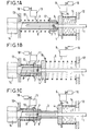
- Figures 1A, 1B and 1C are sectional views longitudinal of a first variant of the device according to the invention in the engaged position, in trigger position and in trigger position.
- Figures 2A, 2B and 2C are sectional views longitudinal of a second variant of the device according to the invention in the engaged position, in trigger position and in trigger position.
- This first spring arrangement 5 is a spring helical coaxial to the operating rod 1 and one of which end is supported on a first fixed part 12 and the other end is supported on the first slide 4, this first spring 5 being kept compressed in the position the circuit breaker is engaged by the first control means 6 consisting of a retractable means for retaining the first slide 4.
- This retaining means 6 is a hooking member cooperating with a flange 15 formed on the first slide 4 and actuated by a trip coil 16.
- the control end 2 of the operating rod 1 is linked to the tubular rod 3 by at least part projection 7 fixed to the operating rod 1 and passing through respectively a longitudinal light 8 arranged on the tubular rod 3 and the control device comprises a second slide 9 said to be interlocked to which the operating rod 1 by its projecting part 7 and subjected to a second arrangement of spring 10 said to engage moving from the triggered position to the engaged position of the circuit breaker under the action of a second control means 11 actuated during an engagement.
- This second spring arrangement 10 is a spring helical coaxial with the tubular rod 3 and one of which end is supported on a second fixed part 13 and the other end is supported on the second slide 9 to which the operating rod 1 is fixed by through its protruding part 7, this second spring 10 being kept compressed in the triggered position of the circuit breaker by the second control means 11 constituted a retractable means for retaining the second slide 9.
- This retaining means 11 is a hooking member cooperating with a flange 17 formed on the first slide 4 and actuated by a latching coil 18.
- the device In the position shown in Figure 1A, the device is in the engaged position.
- the first slide 4 pushed by the rod 3 actuated by the solenoid 14 and by the second slide 9 pushed by the spring 10 is retained by the fastening member 6.
- the free spring 10 pushes the second slide 9 and therefore the end 2 of the rod operation 1 in the engaged position.
- the trigger coil 16 When triggered as shown in the figure 1B, the trigger coil 16 is actuated and releases the spring 5 which pushes the first slide 4 as well as the rod 3 released by the solenoid 14 and the second slide 9 driving the end 2 of the operating rod 1 in triggered position.
- the flange 17 of the second slide 9 is blocked by the attachment member 11.
- the device is then in position to be re quickly engaged by releasing the flange 17 of the second slide 9 in order to return to the engaged position shown in Figure 1A.
- the first trigger spring 5 develops a effort greater than that developed by the second spring said 10 and these springs are therefore dimensioned result.
- Figures 2A, 2B and 2C show a second alternative embodiment of the device according to the invention where the spring arrangements 5, 10 are constituted of snap-action organs with respect to a position of imbalance called neutral.
- the first spring arrangement 5 consists of two telescopic rods 50, 50 ′ whose longitudinal axes are in the same plane, connected at one of their ends in opposite the first slide 4 by respectively a pivoting link 51, 51 'of the yoke type and the other of which end is pivotally fixed at a fixed point 52, 52 ', a spring 53, 53' surrounding the rod 50, 50 'being compressed between the yoke 51, 51 'and the fixed end.
- the first control means 6 is a thrust of the first slide 4. This thrust member is a rod 6 actuated by a trip coil 16.
- the second spring arrangement 10 consists of two telescopic rods 100, 100 'whose axes longitudinal are in the same plane, connected to one of their ends opposite the second slide 9 by respectively a swivel link 101, 101 'of the yoke type and the other end of which is pivotally attached in a fixed point 102, 102 ', a spring 103, 103' surrounding the rod 100, 100 'being compressed between the yoke 101, 101' and the fixed end.
- the second control means 11 is a thrust of the second slide 9. This thrust member is a rod 11 actuated by a trigger coil 18.
- the device In the position shown in Figure 2A, the device is in the engaged position.
- the first slide 4 is pushed by the rod 3 actuated by the solenoid 14.
- the spring arrangement 10 pushes the second slide 9 and so the end 2 of the operating rod 1 in position engaged.
- a flange 17 formed on the second slide 9 abuts against a fixed element non visible. So there is free space on the one hand between the slides 4, 9 and between the projecting part 7 and the end of the light 8.
- the first spring arrangement 5 is in a position very close to its neutral position corresponding to a vertical and aligned position of the rods 50, 50 'in the figure.
- the trigger coil 16 When triggered as shown in the figure 2B, the trigger coil 16 is actuated and drives the outlet of the rod 6 which pushes the spring arrangement 5 and the rod 3 released by the solenoid 14. This is done easily on the aforementioned free space and after this push, spring arrangement 5 has exceeded its point position dead and acts on its own to push rod 3 and the second slide 9 driving the end 2 of the rod operation 1 in the tripped position.
- the second flange 17 slide 9 comes to bear on rod 11 of the coil 18. In this position, it is the second spring arrangement 10 which is in a very position close to its neutral position corresponding to a vertical and aligned position of rods 100, 100 'on the figure.
- the device is then in position to be re quickly engaged by pushing rod 11 of the coil engagement 18 of the second slide 9 in order to return to the engaged position shown in Figure 2A.
- the first arrangement of spring called trigger 5 develops a greater effort than that developed on second arrangement of spring said to engage 10 and these spring arrangements are therefore dimensioned in result.
Landscapes
- Driving Mechanisms And Operating Circuits Of Arc-Extinguishing High-Tension Switches (AREA)
- Refuge Islands, Traffic Blockers, Or Guard Fence (AREA)
- Valve Device For Special Equipments (AREA)
- Breakers (AREA)
- Keying Circuit Devices (AREA)
- Train Traffic Observation, Control, And Security (AREA)
Claims (7)
- Lineare Betätigungsvorrichtung für das Einklinken und Auslösen eines Unterbrechers, die eine Schaltstange (1) mit einem Betätigungsende (2) aufweist, und ein verschiebbares, in die gleiche Längsachse wie die Schaltstange (1) gerichtetes, Hohlrohr (3), das durch eine Zylinderspule (14) betätigt wird und mit der Schaltstange (1), deren Betätigungsende (2) sich innerhalb des Hohlrohres (3) befindet, verbunden ist, und einen ersten Schieber, Auslöseschieber (4) bezeichnet, der auf das Hohlrohr (3) drückt und von der Schaltstange (1) durchquert wird, wobei dieser erste Schieber (4) einer ersten Federanordnung, Auslösefederanordnung (5) bezeichnet, unterliegt, die ihn aus der eingeklinkten Stellung in die ausgelöste Stellung des Unterbrechers unter der Einwirkung eines ersten Betätigungsmittels (6), das beim Auslösen der Betätigungsvorrichtung betätigt wird, versetzt, umfaßt,
dadurch gekennzeichnet, daß das Betätigungsende (2) der Schaltstange (1) mit dem Hohlrohr (3) durch wenigstens einen vorspringenden Teil (7), der an der Schaltstange (1) befestigt ist und jeweils ein auf dem Hohlrohr angeordnetes, längsgerichtetes Langloch (8) durchquert, verbunden ist,
und dadurch, daß die Betätigungsvorrichtung einen zweiten Schieber, Einklinkschieber (9) bezeichnet, aufweist, an dem die Schaltstange (1) durch ihren vorspringenden Teil (7) befestigt ist, wobei dieser einer zweiten Federanordnung, Einklinkfederanordnung bezeichnet, unterliegt, die ihn von der ausgelösten Stellung in die eingeklinkte Stellung des Unterbrechers durch die Betätigung eines zweiten Betätigungsmittels (11), das beim Einklinken betätigt wird, versetzt. - Vorrichtung nach Anspruch 1,
dadurch gekennzeichnet, daß die erste Federanordnung (5) eine schraubenförmige, koaxial zur Schaltstange (1) gerichtete Feder ist, deren eines Ende gegen einen ersten festen Teil (12), und deren anderes Ende gegen den ersten Schieber (4) gedrückt wird, wobei diese erste Feder (5) in der eingeklinkten Stellung des Unterbrechers durch das erste Betätigungsmittel (6), das durch ein einziehbares Mittel zum Halten des ersten Schiebers (4) gebildet wird, zusammengedrückt gehalten wird. - Vorrichtung nach Anspruch 1,
dadurch gekennzeichnet, daß die erste Federanordnung (5) aus zwei Teleskopstangen (50, 50'), deren Längsachsen in der gleichen Ebene liegen, gebildet wird, die mit einem ihrer gegenüberliegenden Enden durch eine drehbare Verbindung (51, 51') jeweils mit dem ersten Schieber (4) verbunden sind, und deren anderes Ende in einem festen Punkt (52, 52') drehbar befestigt ist, wobei eine die Stange (50, 50') umgebende Feder (53, 53') zwischen der drehbaren Verbindung (51, 51') und dem festen Ende zusammengedrückt wird. - Vorrichtung nach Anspruch 3,
dadurch gekennzeichnet, daß das erste Betätigungsmittel (6) eine Druckeinrichtung für den ersten Schieber (4) ist. - Vorrichtung nach einem der vorhergehenden Ansprüche,
dadurch gekennzeichnet, daß die zweite Federanordnung (10) eine schraubenförmige, koaxial zum Hohlrohr (3) gerichtete Feder ist, deren eines Ende gegen einen zweiten festen Teil (13) gedrückt wird, und deren anderes Ende gegen den zweiten Schieber (9), an dem die Schaltstange (1) mittels ihres vorspringenden Teils (7) befestigt ist, gedrückt wird, wobei diese zweite Feder (10) in der ausgelösten Stellung des unterbrechers durch das zweite Betätigungsmittel (11), das aus einem einziehbaren Mittel zum Halten des zweiten Schiebers (9) gebildet wird, zusammengedrückt gehalten wird. - Vorrichtung nach einem der Ansprüche 1 bis 4,
dadurch gekennzeichnet, daß die zweite Federanordnung (10) aus zwei Teleskopstangen (100, 100'), deren Längsachsen in der gleichenEbene liegen, gebildet wird, die mit einem ihrer gegenüberliegenden Enden mit dem zweiten Schieber (9) jeweils durch eine drehbare Verbindung (101, 101') verbunden sind, und deren anderes Ende in einem festen Punkt (102, 102') drehbar verbunden ist, wobei eine die Stange (100, 100') umgebende Feder (103, 103') zwischen der drehbaren Verbindung (101, 101') und dem festen Ende zusammengedrückt gehalten wird. - Vorrichtung nach Anspruch 6,
dadurch gekennzeichnet, daß das zweite Betätigungsmittel (11) eine Druckvorrichtung für den zweiten Schieber (9) ist.
Applications Claiming Priority (2)
| Application Number | Priority Date | Filing Date | Title |
|---|---|---|---|
| FR9315694 | 1993-12-27 | ||
| FR9315694A FR2714522B1 (fr) | 1993-12-27 | 1993-12-27 | Dispositif de commande linéaire pour disjoncteur. |
Publications (2)
| Publication Number | Publication Date |
|---|---|
| EP0660347A1 EP0660347A1 (de) | 1995-06-28 |
| EP0660347B1 true EP0660347B1 (de) | 1999-06-16 |
Family
ID=9454436
Family Applications (1)
| Application Number | Title | Priority Date | Filing Date |
|---|---|---|---|
| EP94403003A Expired - Lifetime EP0660347B1 (de) | 1993-12-27 | 1994-12-23 | Lineare Betätigungseinrichtung für Leistungsschalter |
Country Status (6)
| Country | Link |
|---|---|
| US (1) | US5512869A (de) |
| EP (1) | EP0660347B1 (de) |
| AT (1) | ATE181455T1 (de) |
| DE (1) | DE69419122T2 (de) |
| ES (1) | ES2133514T3 (de) |
| FR (1) | FR2714522B1 (de) |
Families Citing this family (15)
| Publication number | Priority date | Publication date | Assignee | Title |
|---|---|---|---|---|
| FR2741473B1 (fr) * | 1995-11-21 | 1997-12-26 | Gec Alsthom T & D Sa | Organe d'accrochage pour dispositif de commande mecanique de disjoncteur |
| FR2747502B1 (fr) * | 1996-04-10 | 1998-05-15 | Gec Alsthom T & D Sa | Commande a ressorts rectilignes pour disjoncteur a haute tension |
| FR2779565A1 (fr) * | 1998-06-08 | 1999-12-10 | Alsthom Gec | Perfectionnement a une commande a ressorts rectilignes pour disjoncteur a haute tension |
| FR2836277B1 (fr) | 2002-02-19 | 2004-04-16 | Alstom | Mecanisme de commande a ressorts pour disjoncteur a mouvement rectiligne |
| US6657150B1 (en) * | 2002-06-14 | 2003-12-02 | Eaton Corporation | Shorting switch and system to eliminate arcing faults in power distribution equipment |
| FR2868198B1 (fr) * | 2004-03-29 | 2006-05-19 | Areva T & D Ag | Systeme de verrouillage pour une commande lineaire |
| FR2907596B1 (fr) * | 2006-10-18 | 2009-01-23 | Areva T & D Sa | Dispositif de commande d'un appareillage electrique |
| EP2654056A1 (de) * | 2012-04-17 | 2013-10-23 | ABB Technology AG | Notfallöffnungsvorrichtung |
| DE102012104379A1 (de) * | 2012-05-22 | 2013-11-28 | Maschinenfabrik Reinhausen Gmbh | Kraftspeicher für einen Laststufenschalter |
| DE202012012640U1 (de) * | 2012-12-21 | 2013-10-01 | Methode Electronics Malta Ltd. | Auslösevorrichtung für ein Schütz |
| US9184014B2 (en) * | 2013-02-01 | 2015-11-10 | General Electric Company | Electrical operator for circuit breaker and method thereof |
| CN103531371B (zh) * | 2013-10-18 | 2015-09-02 | 通能顺达科技国际有限公司 | 一种快速双向三状态切换电力开关装置 |
| DE102015218700A1 (de) | 2015-09-29 | 2017-03-30 | Siemens Aktiengesellschaft | Anordnung und Verfahren zum Antreiben eines Leistungsschalters mit gleichen Richtungen der Feder- und Antriebskraft |
| EP3731250B8 (de) | 2019-04-23 | 2022-02-09 | Hitachi Energy Switzerland AG | Federeinheit und lastumschalter |
| CN110335793A (zh) * | 2019-06-21 | 2019-10-15 | 福建省三星电气股份有限公司 | 一种传动装置及使用该传动装置的断路器 |
Family Cites Families (5)
| Publication number | Priority date | Publication date | Assignee | Title |
|---|---|---|---|---|
| US1606738A (en) * | 1919-10-11 | 1926-11-16 | Westinghouse Electric & Mfg Co | Control apparatus |
| US3304444A (en) * | 1963-11-01 | 1967-02-14 | Eugene S Smith | Control device for an electrical switch |
| US3772620A (en) * | 1971-04-12 | 1973-11-13 | Deltrol Corp | Condition control device and system |
| US3845433A (en) * | 1973-09-28 | 1974-10-29 | Arrow Hart Inc | Switch operator with tripping means |
| FR2589001A1 (fr) * | 1985-10-23 | 1987-04-24 | Alsthom | Dispositif de manoeuvre d'un disjoncteur et disjoncteur muni de ce dispositif |
-
1993
- 1993-12-27 FR FR9315694A patent/FR2714522B1/fr not_active Expired - Fee Related
-
1994
- 1994-12-23 ES ES94403003T patent/ES2133514T3/es not_active Expired - Lifetime
- 1994-12-23 EP EP94403003A patent/EP0660347B1/de not_active Expired - Lifetime
- 1994-12-23 AT AT94403003T patent/ATE181455T1/de not_active IP Right Cessation
- 1994-12-23 DE DE69419122T patent/DE69419122T2/de not_active Expired - Fee Related
- 1994-12-23 US US08/362,928 patent/US5512869A/en not_active Expired - Fee Related
Also Published As
| Publication number | Publication date |
|---|---|
| US5512869A (en) | 1996-04-30 |
| EP0660347A1 (de) | 1995-06-28 |
| FR2714522A1 (fr) | 1995-06-30 |
| DE69419122T2 (de) | 1999-12-09 |
| FR2714522B1 (fr) | 1996-02-02 |
| DE69419122D1 (de) | 1999-07-22 |
| ES2133514T3 (es) | 1999-09-16 |
| ATE181455T1 (de) | 1999-07-15 |
Similar Documents
| Publication | Publication Date | Title |
|---|---|---|
| EP0660347A1 (de) | Linearer Betätigungseinrichtung für Leistungsschalter | |
| FR2631485A1 (fr) | Mecanisme de commande de disjoncteur miniature a indicateur de soudure des contacts | |
| FR2580426A1 (fr) | Disjoncteur pour basse tension avec fonction de commutation pour commande de systeme de gestion d'energie electrique | |
| EP0205361B1 (de) | Handbetätigte Schnapp-Schliesseinrichtung eines Miniaturschutzschalters | |
| EP0766280A2 (de) | Befehls- und Meldegerät für Schutzschalter | |
| EP1026712A1 (de) | Anlage mit einem elektrischen Schalter und Verriegelung durch einen Kabel | |
| FR2954852A1 (fr) | Dispositif de declenchement de relais de surcharge | |
| EP1873807B1 (de) | Elektrische Schutzeinrichtung, die von einer Zusatzsteuervorrichtung gesteuert wird | |
| BE1000208A6 (fr) | Dispositif d'entrainement destine a l'enclenchement et au declenchement telecommande d'un interrupteur automatique. | |
| EP0161946A1 (de) | An einen Schutzschalter ankuppelbare Zusatzeinheit | |
| EP1209712A1 (de) | Fernsteuervorrictung für modulares Schutzgerät | |
| FR2685976A1 (fr) | Mecanisme pour appareil interrupteur de courant. | |
| FR2500957A1 (fr) | Mecanisme pour declencheur de courant de fuite combine avec un disjoncteur de protection de lignes | |
| FR2789220A1 (fr) | Mecanisme de commande d'un disjoncteur electrique | |
| BE1004453A7 (fr) | Commutateur supplementaire a monter sur un commutateur de protection de conducteur. | |
| FR2535443A1 (fr) | Dispositif d'aeration et d'evacuation des fumees, notamment pour locaux industriels ou recevant du public | |
| FR2623938A1 (fr) | Additif de signalisation de defaut pour appareil electrique de protection | |
| EP0897188A1 (de) | Steuervorrichtung für elektrischer Schutzapparat wie ein Schutzschalter mit einer Anzeigevorrichtung zur Auslösung, und Schutzschalter ausgerüstet mit einer solchen Vorrichtung | |
| FR2959594A1 (fr) | Dispositif de telecommande et disjoncteur telecommande equipe d'un tel dispositif. | |
| EP2237302B1 (de) | Vorrichtung zur thermischen Auslösung für elektrisches Schutzgerät | |
| FR2667978A1 (fr) | Disjoncteur a ecran coupe-arc. | |
| CA1227827A (fr) | Interrupteur de protection automatique a sectionnement visible et a rearmement manuel | |
| EP0800189B1 (de) | Betätigungseinrichtung für elektrisches Gerät wie Schutzschalter | |
| FR2512584A1 (fr) | Contacteur disjoncteur a fonctionnement automatique et manuel en marche forcee | |
| FR2492584A1 (fr) | Mecanisme d'armement pour disjoncteur a action brusque |
Legal Events
| Date | Code | Title | Description |
|---|---|---|---|
| PUAI | Public reference made under article 153(3) epc to a published international application that has entered the european phase |
Free format text: ORIGINAL CODE: 0009012 |
|
| AK | Designated contracting states |
Kind code of ref document: A1 Designated state(s): AT CH DE ES FR GB IT LI SE |
|
| 17P | Request for examination filed |
Effective date: 19951106 |
|
| GRAG | Despatch of communication of intention to grant |
Free format text: ORIGINAL CODE: EPIDOS AGRA |
|
| GRAG | Despatch of communication of intention to grant |
Free format text: ORIGINAL CODE: EPIDOS AGRA |
|
| GRAH | Despatch of communication of intention to grant a patent |
Free format text: ORIGINAL CODE: EPIDOS IGRA |
|
| 17Q | First examination report despatched |
Effective date: 19981130 |
|
| GRAH | Despatch of communication of intention to grant a patent |
Free format text: ORIGINAL CODE: EPIDOS IGRA |
|
| GRAA | (expected) grant |
Free format text: ORIGINAL CODE: 0009210 |
|
| AK | Designated contracting states |
Kind code of ref document: B1 Designated state(s): AT CH DE ES FR GB IT LI SE |
|
| REF | Corresponds to: |
Ref document number: 181455 Country of ref document: AT Date of ref document: 19990715 Kind code of ref document: T |
|
| REG | Reference to a national code |
Ref country code: CH Ref legal event code: EP |
|
| REF | Corresponds to: |
Ref document number: 69419122 Country of ref document: DE Date of ref document: 19990722 |
|
| REG | Reference to a national code |
Ref country code: CH Ref legal event code: NV Representative=s name: CABINET ROLAND NITHARDT CONSEILS EN PROPRIETE INDU |
|
| REG | Reference to a national code |
Ref country code: ES Ref legal event code: FG2A Ref document number: 2133514 Country of ref document: ES Kind code of ref document: T3 |
|
| GBT | Gb: translation of ep patent filed (gb section 77(6)(a)/1977) |
Effective date: 19991220 |
|
| PLBE | No opposition filed within time limit |
Free format text: ORIGINAL CODE: 0009261 |
|
| STAA | Information on the status of an ep patent application or granted ep patent |
Free format text: STATUS: NO OPPOSITION FILED WITHIN TIME LIMIT |
|
| 26N | No opposition filed | ||
| REG | Reference to a national code |
Ref country code: GB Ref legal event code: IF02 |
|
| PGFP | Annual fee paid to national office [announced via postgrant information from national office to epo] |
Ref country code: CH Payment date: 20031201 Year of fee payment: 10 |
|
| PGFP | Annual fee paid to national office [announced via postgrant information from national office to epo] |
Ref country code: DE Payment date: 20031205 Year of fee payment: 10 |
|
| PGFP | Annual fee paid to national office [announced via postgrant information from national office to epo] |
Ref country code: FR Payment date: 20031209 Year of fee payment: 10 |
|
| REG | Reference to a national code |
Ref country code: CH Ref legal event code: PFA Owner name: ALSTOM T & D SA Free format text: GEC ALSTHOM T & D SA#38, AVENUE KLEBER#75116 PARIS (FR) -TRANSFER TO- ALSTOM T & D SA#25, AVENUE KLEBER#75116 PARIS (FR) |
|
| PGFP | Annual fee paid to national office [announced via postgrant information from national office to epo] |
Ref country code: ES Payment date: 20041203 Year of fee payment: 11 |
|
| PGFP | Annual fee paid to national office [announced via postgrant information from national office to epo] |
Ref country code: SE Payment date: 20041206 Year of fee payment: 11 |
|
| PGFP | Annual fee paid to national office [announced via postgrant information from national office to epo] |
Ref country code: AT Payment date: 20041213 Year of fee payment: 11 |
|
| PGFP | Annual fee paid to national office [announced via postgrant information from national office to epo] |
Ref country code: GB Payment date: 20041222 Year of fee payment: 11 |
|
| PG25 | Lapsed in a contracting state [announced via postgrant information from national office to epo] |
Ref country code: LI Free format text: LAPSE BECAUSE OF NON-PAYMENT OF DUE FEES Effective date: 20041231 Ref country code: CH Free format text: LAPSE BECAUSE OF NON-PAYMENT OF DUE FEES Effective date: 20041231 |
|
| REG | Reference to a national code |
Ref country code: FR Ref legal event code: CD Ref country code: FR Ref legal event code: CA |
|
| PG25 | Lapsed in a contracting state [announced via postgrant information from national office to epo] |
Ref country code: DE Free format text: LAPSE BECAUSE OF NON-PAYMENT OF DUE FEES Effective date: 20050701 |
|
| REG | Reference to a national code |
Ref country code: CH Ref legal event code: PL |
|
| PG25 | Lapsed in a contracting state [announced via postgrant information from national office to epo] |
Ref country code: FR Free format text: LAPSE BECAUSE OF NON-PAYMENT OF DUE FEES Effective date: 20050831 |
|
| REG | Reference to a national code |
Ref country code: FR Ref legal event code: ST |
|
| PG25 | Lapsed in a contracting state [announced via postgrant information from national office to epo] |
Ref country code: IT Free format text: LAPSE BECAUSE OF NON-PAYMENT OF DUE FEES;WARNING: LAPSES OF ITALIAN PATENTS WITH EFFECTIVE DATE BEFORE 2007 MAY HAVE OCCURRED AT ANY TIME BEFORE 2007. THE CORRECT EFFECTIVE DATE MAY BE DIFFERENT FROM THE ONE RECORDED. Effective date: 20051223 Ref country code: GB Free format text: LAPSE BECAUSE OF NON-PAYMENT OF DUE FEES Effective date: 20051223 Ref country code: AT Free format text: LAPSE BECAUSE OF NON-PAYMENT OF DUE FEES Effective date: 20051223 |
|
| PG25 | Lapsed in a contracting state [announced via postgrant information from national office to epo] |
Ref country code: SE Free format text: LAPSE BECAUSE OF NON-PAYMENT OF DUE FEES Effective date: 20051224 Ref country code: ES Free format text: LAPSE BECAUSE OF NON-PAYMENT OF DUE FEES Effective date: 20051224 |
|
| EUG | Se: european patent has lapsed | ||
| GBPC | Gb: european patent ceased through non-payment of renewal fee |
Effective date: 20051223 |
|
| REG | Reference to a national code |
Ref country code: ES Ref legal event code: FD2A Effective date: 20051224 |