EP0660375B1 - Elektrodenlose-Fluoreszenzlampe - Google Patents
Elektrodenlose-Fluoreszenzlampe Download PDFInfo
- Publication number
- EP0660375B1 EP0660375B1 EP94308794A EP94308794A EP0660375B1 EP 0660375 B1 EP0660375 B1 EP 0660375B1 EP 94308794 A EP94308794 A EP 94308794A EP 94308794 A EP94308794 A EP 94308794A EP 0660375 B1 EP0660375 B1 EP 0660375B1
- Authority
- EP
- European Patent Office
- Prior art keywords
- lamp
- housing
- vessel
- lamp according
- coating
- Prior art date
- Legal status (The legal status is an assumption and is not a legal conclusion. Google has not performed a legal analysis and makes no representation as to the accuracy of the status listed.)
- Expired - Lifetime
Links
- 239000011248 coating agent Substances 0.000 claims description 42
- 238000000576 coating method Methods 0.000 claims description 42
- 238000004804 winding Methods 0.000 claims description 13
- 239000000463 material Substances 0.000 claims description 10
- 239000004020 conductor Substances 0.000 claims description 5
- 229920000728 polyester Polymers 0.000 claims description 5
- 230000008878 coupling Effects 0.000 claims description 2
- 238000010168 coupling process Methods 0.000 claims description 2
- 238000005859 coupling reaction Methods 0.000 claims description 2
- 229920000515 polycarbonate Polymers 0.000 claims description 2
- 239000004417 polycarbonate Substances 0.000 claims description 2
- 230000001419 dependent effect Effects 0.000 claims 1
- 239000003990 capacitor Substances 0.000 description 11
- 239000011521 glass Substances 0.000 description 6
- 229920004142 LEXAN™ Polymers 0.000 description 4
- 239000004418 Lexan Substances 0.000 description 4
- OAICVXFJPJFONN-UHFFFAOYSA-N Phosphorus Chemical compound [P] OAICVXFJPJFONN-UHFFFAOYSA-N 0.000 description 4
- 239000000853 adhesive Substances 0.000 description 4
- 230000001070 adhesive effect Effects 0.000 description 4
- 239000004033 plastic Substances 0.000 description 4
- 229920003023 plastic Polymers 0.000 description 4
- 230000005284 excitation Effects 0.000 description 3
- 238000001914 filtration Methods 0.000 description 3
- 229910052751 metal Inorganic materials 0.000 description 3
- 239000002184 metal Substances 0.000 description 3
- GWEVSGVZZGPLCZ-UHFFFAOYSA-N Titan oxide Chemical compound O=[Ti]=O GWEVSGVZZGPLCZ-UHFFFAOYSA-N 0.000 description 2
- 239000004411 aluminium Substances 0.000 description 2
- 229910052782 aluminium Inorganic materials 0.000 description 2
- XAGFODPZIPBFFR-UHFFFAOYSA-N aluminium Chemical compound [Al] XAGFODPZIPBFFR-UHFFFAOYSA-N 0.000 description 2
- 230000005672 electromagnetic field Effects 0.000 description 2
- QSHDDOUJBYECFT-UHFFFAOYSA-N mercury Chemical compound [Hg] QSHDDOUJBYECFT-UHFFFAOYSA-N 0.000 description 2
- 229910052753 mercury Inorganic materials 0.000 description 2
- 229920001296 polysiloxane Polymers 0.000 description 2
- 238000007789 sealing Methods 0.000 description 2
- 229910000859 α-Fe Inorganic materials 0.000 description 2
- 235000001674 Agaricus brunnescens Nutrition 0.000 description 1
- 229910000497 Amalgam Inorganic materials 0.000 description 1
- RYGMFSIKBFXOCR-UHFFFAOYSA-N Copper Chemical compound [Cu] RYGMFSIKBFXOCR-UHFFFAOYSA-N 0.000 description 1
- 230000004888 barrier function Effects 0.000 description 1
- 230000005684 electric field Effects 0.000 description 1
- 239000012799 electrically-conductive coating Substances 0.000 description 1
- 230000004927 fusion Effects 0.000 description 1
- 239000000696 magnetic material Substances 0.000 description 1
- 238000004519 manufacturing process Methods 0.000 description 1
- 238000012216 screening Methods 0.000 description 1
- 239000004332 silver Substances 0.000 description 1
- 229910052709 silver Inorganic materials 0.000 description 1
- XOLBLPGZBRYERU-UHFFFAOYSA-N tin dioxide Chemical compound O=[Sn]=O XOLBLPGZBRYERU-UHFFFAOYSA-N 0.000 description 1
- 229910001887 tin oxide Inorganic materials 0.000 description 1
- 239000004408 titanium dioxide Substances 0.000 description 1
Images


Classifications
-
- H—ELECTRICITY
- H01—ELECTRIC ELEMENTS
- H01J—ELECTRIC DISCHARGE TUBES OR DISCHARGE LAMPS
- H01J65/00—Lamps without any electrode inside the vessel; Lamps with at least one main electrode outside the vessel
- H01J65/04—Lamps in which a gas filling is excited to luminesce by an external electromagnetic field or by external corpuscular radiation, e.g. for indicating plasma display panels
-
- H—ELECTRICITY
- H01—ELECTRIC ELEMENTS
- H01J—ELECTRIC DISCHARGE TUBES OR DISCHARGE LAMPS
- H01J61/00—Gas-discharge or vapour-discharge lamps
- H01J61/02—Details
- H01J61/56—One or more circuit elements structurally associated with the lamp
-
- H—ELECTRICITY
- H01—ELECTRIC ELEMENTS
- H01J—ELECTRIC DISCHARGE TUBES OR DISCHARGE LAMPS
- H01J61/00—Gas-discharge or vapour-discharge lamps
- H01J61/02—Details
- H01J61/04—Electrodes; Screens; Shields
-
- H—ELECTRICITY
- H01—ELECTRIC ELEMENTS
- H01J—ELECTRIC DISCHARGE TUBES OR DISCHARGE LAMPS
- H01J61/00—Gas-discharge or vapour-discharge lamps
- H01J61/02—Details
- H01J61/30—Vessels; Containers
-
- H—ELECTRICITY
- H01—ELECTRIC ELEMENTS
- H01J—ELECTRIC DISCHARGE TUBES OR DISCHARGE LAMPS
- H01J61/00—Gas-discharge or vapour-discharge lamps
- H01J61/02—Details
- H01J61/30—Vessels; Containers
- H01J61/35—Vessels; Containers provided with coatings on the walls thereof; Selection of materials for the coatings
-
- H—ELECTRICITY
- H01—ELECTRIC ELEMENTS
- H01J—ELECTRIC DISCHARGE TUBES OR DISCHARGE LAMPS
- H01J65/00—Lamps without any electrode inside the vessel; Lamps with at least one main electrode outside the vessel
- H01J65/04—Lamps in which a gas filling is excited to luminesce by an external electromagnetic field or by external corpuscular radiation, e.g. for indicating plasma display panels
- H01J65/042—Lamps in which a gas filling is excited to luminesce by an external electromagnetic field or by external corpuscular radiation, e.g. for indicating plasma display panels by an external electromagnetic field
- H01J65/048—Lamps in which a gas filling is excited to luminesce by an external electromagnetic field or by external corpuscular radiation, e.g. for indicating plasma display panels by an external electromagnetic field the field being produced by using an excitation coil
Definitions
- the present invention relates to an electrodeless fluorescent lamp.
- US-A-4727294 U.S. Philips Corporation
- the lamp of US-A-4727294 comprises an externally spherical lamp vessel which is sealed and which contains a fill capable of sustaining a discharge when suitably excited.
- the discharge excites a phosphor coating on the inside of the vessel.
- the fill is excited by a core of magnetic material surrounded by a winding which is energised by a high frequency oscillator.
- the core and winding project into a cylindrical sealing member of the vessel which projects, in re-entrant fashion, into the spherical vessel.
- the lamp vessel is further provided with a light transparent, electrically conductive layer within the vessel to substantially confine the electric field generated by the core and winding within the vessel.
- a portion of the external surface of the vessel is also provided with a conductive coating capacitively coupled to the conductive layer inside the vessel.
- the external coating is connected by a conductor to a power mains terminal of the lamp.
- An electrically insulative, generally cylindrical, housing supports the spherical lamp vessel and the reentrant sealing member.
- the housing has a diameter much smaller than the spherical lamp vessel,
- the housing contains the oscillator circuit and mechanically connects the lamp vessel to the lamp cap.
- the portion of the external surface of the vessel which is provided with the conductive coating is inside the housing.
- an electrodeless fluorescent lamp comprising a sealed lamp vessel containing a luminescent layer, a fill capable of sustaining a discharge when suitably excited, and a coating of electrically conductive light transmissive material on the internal surface of the vessel;
- the lamp vessel may include a reflective layer which reflects light from the said second portion to the said first portion.
- the housing grips, and thereby supports, the lamp vessel around the zone of maximum extent.
- the lamp vessel is fixed to, and thereby supported by, a support of the energising means.
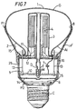
- the illustrative fluorescent electrodeless lamp of FIGURE 1 comprises a sealed glass lamp vessel G which is 'mushroom' shaped having a face 1 which is a section of a sphere and a curved body 2 tapering away from the face 1.
- a reentrant cylinder 3 also of glass is fused to the body 2.
- the vessel contains a fill (not shown) e.g. of mercury and a rare gas, which when excited, produces a discharge of ultraviolet (UV) light.
- a fill e.g. of mercury and a rare gas, which when excited, produces a discharge of ultraviolet (UV) light.
- UV ultraviolet
- On the internal surface of the vessel G and on the surface of the cylinder 3 is a layer of phosphor P which converts the UV light into visible light, as in a conventional fluorescent lamp.
- the fill is excited by an electromagnetic field produced by a winding, comprising many turns of copper wire, arranged around a magnetic core of e.g. ferrite.
- the winding and core 4 are arranged in the re-entrant cylinder 3.
- the winding is excited at high frequency e.g. 2.65 MHz by an excitation circuit comprising an oscillator 5 powered from the power mains by a rectifier 6.
- EMI electromagnetic interference
- One mode of EMI is the high frequency electromagnetic field produced by the winding.
- the other mode is conducted interference which comprises high frequency currents which may be capacitively coupled by stray capacitance to the mains.
- a light transparent, electrically conductive coating FTO is provided over the face 1 and body 2 of the lamp vessel, but not the cylinder 3.
- the coating has sufficient resistance e.g. 300 ohms per square so that it does not present a short-circuit to the winding 4.
- the coating FTO is preferably of fluorine-doped tin oxide but may be of other materials as known to be suitable in the art.
- a conductive coating Al is provided on the outside of the lamp vessel, capacitively coupled to the internal coating FTO.
- the external coating Al may be aluminium or silver or any other suitable conductive coating.
- the coating A1 is electrically coupled to a radio frequency ground point in the excitation circuit.
- the radio frequency ground point may be one side of the power mains or on the RF side of RF filtering components within the excitation circuit.
- the coating A1 is electrically connected via a capacitor 7 to one side of the power means; the capacitor 7 is then a mains decoupling capacitor chosen to have low-impedance at the oscillator frequency, e.g. 2.65 MHz, and high impedance at mains frequency.
- Such capacitors are well known.
- the coating A1 may be directly connected to the RF ground point.
- the RF ground point is preferably on the RF side of the RF filtering components. Such direct connection of the coating A1 to the RF side of the filtering components is currently preferred.
- the external coating Al covers the entire body 2 except for a strip 9 (shown in Figure 2) of the body 2) which is left bare of coating so that the coating Al does not form a continuous loop around the vessel.
- the coating Al is spaced from the zone 8 of maximum diameter of the lamp vessel.
- the coating Al does not extend over the face 1 nor over the reentrant cylinder 3.
- the capacitor 7 of Figure 1 is connected to the coating Al by a conductor which is fixed to the coating Al by an electrically conductive adhesive, e.g. Silicone RTV available from GE Plastics, a division of the General Electrical Company, of New York State, USA.
- an electrically conductive adhesive e.g. Silicone RTV available from GE Plastics, a division of the General Electrical Company, of New York State, USA.
- the conductive coating FTO is formed on the glass G of the vessel.
- a light reflective layer R is provided between the coating FTO and the phosphor P.
- the reflective layer R is preferably of titanium dioxide although other suitable light reflective materials could be used.
- the reflective layer R covers the body 2, but not the face 1, being spaced from the zone 8 of maximum diameter.
- the reflective layer R covers also the cylinder 3.
- the reflective layer R reflects light produced by the phosphor layer P forward to the face 1.
- An electrically insulative plastics housing H is provided to:
- the housing must withstand the heat generated by the lamp.
- the housing H is preferably opaque but could be transparent.
- Figure 2 shows the lamp as it would appear if the housing were transparent.
- the housing is fixed inside the lamp cap C by any suitable means.
- the cap being of metal, and the housing of plastic, the cap may be staked to the housing.
- circuit boards such as indicated at 10 provide the circuitry of the rectifier 6, oscillator 5 and the capacitor 7.
- the boards are supported by grooves in the housing.
- a barrier and support 11 supported by grooves in the housing further supports the core and winding 4.
- a second portion of the housing H extends over the body 2 of the lamp vessel covering the external coating Al and, in this embodiment of the invention, engages the lamp vessel around the zone 8 of maximum diameter.
- the maximum diameter of the glass vessel G varies by as much as ⁇ 0.8mm.
- the housing must hold the glass vessel firmly and safely in position over the whole range of variation in diameter.
- the housing H may be of one piece, which is of material flexible to accommodate the variations. Either the housing is made of sufficiently flexible material (as shown in Figure 2) or fingers separated by slits 30 may be formed in the housing to provide the required flexibility as shown in Figure 3.
- Suitable materials are a polycarbonate such as LEXAN (Trade Mark) produced by GE Plastics, a division of the General Electric Company of New York State, U.S.A. or glass-reinforced polyester.
- the housing may be formed in two halves H41 and H42 which are joined axially of the lamp around the lamp components.
- the halves may be fixed together by any suitable means examples including ratchets, pegs, adhesive, and fusion of the two halves.
- Suitable materials for such a housing are LEXAN or glass-reinforced polyester.
- the housing is formed in two parts.
- a first part H51 extends in one piece, from the cap towards the zone 8 of maximum diameter like the housing of Figure 2 but unlike the housing of Figure 2 does not extend beyond that zone.
- a second part is a ring H52 which extends over the zone 8 of maximum diameter and fixed to the first part H51 to grip the lamp vessel G.
- Suitable materials are LEXAN or glass-reinforced polyester.
- FIG. 6 Another alternative shown in Figure 6 comprises two parts, the first (P1) covering the evacuated envelope and the second (P2) covering the electronics.
- the two parts are fixed together (S) by any suitable means, e.g. a snap-fit arrangement.
- suitable materials are LEXAN or glass-reinforced polyester.
- FIGURE 7 shows an embodiment of the invention in accordance with another aspect of the invention.
- Indicia similar to those used in the other Figures refer to elements similar to those shown in, and described with reference to the other Figures.
- the sealed glass lamp vessel G of Figure 7 is generally of the same shape as the vessels G of Figures 1 to 6, and has the same layers FTO, R, P on the inside thereof and the same layer A1 on the outside thereof; (the layers are not indicated in Figure 7).
- Figure 7 shows tubulation T which extends axially of the lamp through the winding and core 4 towards the cap C.
- the tubulation houses mercury amalgam M, held in place by a dimple D in the tubulation.
- the energising circuitry 5, 6, 7 is housed within the housing H' inside an electrical screen S.
- the screen S comprises a closed metal box having cylindrical side wall 10 conforming in shape to the shape of the housing H' and lower and upper end walls 14 and 12.
- the side wall 5 extends beyond the lower wall 14 towards the cap C and supports the rectifier circuit board 6.
- the oscillator circuit 5 on board 10 is supported within the closed box 14, 12, 5.
- the decoupling capacitor 7 may also be in the box.
- Electrodes 13 upstand from the board 10 and provide electrical connection to the winding 4.
- the support 11 of the winding 4 and ferrite core is supported by the top wall 12 of the metal box.
- the lamp vessel G is fixed to the support 11 by electrical conductive adhesive such as Silicone RTV.
- the electrically conductive adhesive provides electrical connection between the external conductive coating AL and the decoupling capacitor 7.
- the decoupling capacitor 7 may be replaced by a direct connection to the RF ground point.
- the housing H' functions to:
- the housing H' of Figure 7 does not function to grip the vessel G.
- the housing H' of Figure 7 supports a truncated hollow cone 15 of electrical conductor, - e.g. aluminium, which is electrically insulated from the external coating Al.
- the cone 15 forms a single continuous electrical turn around the lamp vessel.
- the housing H' of Figure 7 comprises two portions P1 and P2.
- Portion P2 supports the cap C and houses the energising circuitry 5, 6, 7 and the electrical screening box S.
- the portion P1 surrounds the lamp vessel G, electrically isolates the external coating H, and supports the cone 15.
- the portions P1 and P2 are connected by a snap-fit arrangement 16 but may be connected by any suitable connecting means.
Landscapes
- Physics & Mathematics (AREA)
- Engineering & Computer Science (AREA)
- Plasma & Fusion (AREA)
- Electromagnetism (AREA)
- Non-Portable Lighting Devices Or Systems Thereof (AREA)
- Discharge Lamps And Accessories Thereof (AREA)
- Circuit Arrangements For Discharge Lamps (AREA)
Claims (14)
- Elektrodenlose Leuchtstofflampe enthaltend:einen gekapselten Lampenkolben (G), der eine Lumineszenzschicht (P), eine Füllung, die eine Entladung aufrecht erhalten kann, wenn sie in geeigneter Weise angeregt wird, und einen Überzug aus elektrisch leitfähigem, lichtdurchlässigem Material (FTO) auf der inneren Oberfläche des Kolbens enthält,eine elektrische Versorgungseinrichtung (4,5,6) zum Anregen der Füllung undein elektrisch isolierendes Gehäuse (H), das einen ersten Gehäuseabschnitt aufweist, von dem der Lampenkolben (G) ausgeht und der einen Teil (5,6) der elektrischen Versorgungseinrichtung unterbringt, dadurch gekennzeichnet, daßdas Gehäuse einen zweiten Gehäuseabschnitt aufweist, von dem der erste Gehäuseabschnitt ausgeht und der einen Körperabschnitt (2) von dem Lampenkolben einschließt, undein Überzug (Al) aus elektrisch leitfähigem Material auf der äußeren Oberfläche von dem Abschnitt (2) des Lampenkolbens vorgesehen ist, der von dem zweiten Gehäuseabschnitt eingeschlossen ist, wobei der äußere Überzug durch den zweiten Gehäuseabschnitt elektrisch isoliert und mit dem inneren Überzug kapazitiv gekoppelt ist, undeine Vorrichtung (7) den äußeren Überzug (Al) mit dem elektrischen Erdpunkt koppelt, um geleitete Störungen zu verkleinern.
- Lampe nach Anspruch 1, wobei der gekapselte Lampenkolben einen zylindrischen zurückspringenden Abschnitt (3) aufweist,die Versorgungseinrichtung eine elektromagnetische Wicklung (4) aufweist, die in den zurückspringenden Abschnitt des Lampenkolbens vorsteht, um die Entladung anzuregen.
- Lampe nach Anspruch 2, ferner enthaltend: eine Lampenkappe (C), wobei das elektrisch isolierende Gehäuse (H) an der Kappe befestigt ist.
- Lampe nach Anspruch 1, 2 oder 3, wobei:der Kolben (G) eine Zone (8) mit maximalem Durchmesser hat und zum Emittieren von Licht aus wenigstens einem Stirnflächenabschnitt (1) des Kolbens angeordnet ist, der von der Zone (8) begrenzt ist,das Gehäuse sich über einen von der Zone begrenzten Körperabschnitt (2) des Kolbens erstreckt undder äußere leitfähige Überzug (FTO) sich über im wesentlichen den gesamten Körperabschnitt (2) von dem Kolben erstreckt und durch das Gehäuse elektrisch isoliert ist.
- Lampe nach Anspruch 1, 2, 3 oder 4, wobei der Kolben von einer Halterung der elektrischen Versorgungseinrichtung gehaltert und daran befestigt ist.
- Lampe nach Anspruch 4, wobei das Gehäuse (H) den Kolben (G) um die Zone (8) maximalen Durchmessers herum ergreift.
- Lampe nach Anspruch 6, wobei das Gehäuse (H) zwei Hälften (H41, H42) aufweist, die axial zur Lampe miteinander verbunden sind.
- Lampe nach Anspruch 6, wobei das Gehäuse (H) flexible Finger aufweist, die durch Schlitze (30) in der Zone maximalen Durchmessers getrennt sind.
- Lampe nach Anspruch 5 oder 6, wobei das Gehäuse zwei Teile aufweist, ein Teil (P2), an dem die Kappe befestigt ist und der die Versorgungseinrichtung unterbringt, und ein weiterer Teil (P1), der sich zur Zone maximalen Durchmessers erstreckt und an dem ersten Teil befestigt ist.
- Lampe nach einem der Ansprüche 4 und 6 bis 9 oder 5, wenn er von Anspruch 4 abhängig ist, wobei der Lampenkolben eine lichtreflektierende Schicht (R) aufweist, die sich im wesentlichen von der Zone (8) in Richtung auf die Lampenkappe (C) erstreckt.
- Lampe nach Anspruch 10, wobei die lichtreflektierende Schicht Licht von dem Körperabschnitt (2) zu dem Stirnflächenabschnitt (1) des Kolbens reflektiert.
- Lampe nach einem der vorstehenden Ansprüche, wobei das Gehäuse (H) aus Polycarbonat oder glasfaserverstärktem Polyester ist.
- Lampe nach einem der vorstehenden Ansprüche, wobei der äußere leitfähige Überzug (Al) elektrisch mit einer Hochfrequenzerdung der Versorgungseinrichtung gekoppelt ist.
- Lampe nach Anspruch 13, wobei die Hochfrequenzerdung elektrisch mit einem Netzleitungsanschluß der Lampe gekoppelt ist.
Applications Claiming Priority (2)
| Application Number | Priority Date | Filing Date | Title |
|---|---|---|---|
| GB939326123A GB9326123D0 (en) | 1993-12-22 | 1993-12-22 | Electrodeless fluorescent lamp |
| GB9326123 | 1993-12-22 |
Publications (3)
| Publication Number | Publication Date |
|---|---|
| EP0660375A2 EP0660375A2 (de) | 1995-06-28 |
| EP0660375A3 EP0660375A3 (de) | 1996-11-13 |
| EP0660375B1 true EP0660375B1 (de) | 2000-03-15 |
Family
ID=10746984
Family Applications (1)
| Application Number | Title | Priority Date | Filing Date |
|---|---|---|---|
| EP94308794A Expired - Lifetime EP0660375B1 (de) | 1993-12-22 | 1994-11-29 | Elektrodenlose-Fluoreszenzlampe |
Country Status (7)
| Country | Link |
|---|---|
| US (1) | US5668433A (de) |
| EP (1) | EP0660375B1 (de) |
| JP (1) | JP3550201B2 (de) |
| KR (1) | KR950020957A (de) |
| CA (1) | CA2138602A1 (de) |
| DE (1) | DE69423445T2 (de) |
| GB (1) | GB9326123D0 (de) |
Families Citing this family (21)
| Publication number | Priority date | Publication date | Assignee | Title |
|---|---|---|---|---|
| JP3332676B2 (ja) | 1994-08-02 | 2002-10-07 | キヤノン株式会社 | 電子放出素子、電子源及び画像形成装置と、それらの製造方法 |
| US5702179A (en) * | 1995-10-02 | 1997-12-30 | Osram Sylvania, Inc. | Discharge lamp having light-transmissive conductive coating for RF containment and heating |
| GB9521375D0 (en) * | 1995-10-18 | 1995-12-20 | Gen Electric | Electrodeless fluorescent lamp |
| GB9521373D0 (en) * | 1995-10-18 | 1995-12-20 | Gen Electric | Electrodeless fluorescent lamp |
| DE29519182U1 (de) * | 1995-12-04 | 1996-01-25 | Hahn, Walter, 95349 Thurnau | Beleuchtungseinrichtung mit einer Induktions-Reflektorlampe |
| GB9603198D0 (en) * | 1996-02-15 | 1996-04-17 | Gen Electric | Controlling the transmission of light frome light sources |
| GB9603197D0 (en) | 1996-02-15 | 1996-04-17 | Gen Electric | Electrodeless discharge lamp |
| GB2314689A (en) * | 1996-06-26 | 1998-01-07 | Gen Electric | Coil assembly |
| GB2314671A (en) * | 1996-06-26 | 1998-01-07 | Gen Electric | Electrodeless fluorescent lamp |
| DE19844548A1 (de) * | 1998-09-29 | 2000-03-30 | Patent Treuhand Ges Fuer Elektrische Gluehlampen Mbh | Entladungslampe und Beleuchtungssystem mit einer Entladungslampe |
| CN1383184A (zh) * | 2001-04-26 | 2002-12-04 | 松下电器产业株式会社 | 灯泡状无电极放电灯及无电极放电灯 |
| DE10222100A1 (de) * | 2002-05-17 | 2003-11-27 | Patent Treuhand Ges Fuer Elektrische Gluehlampen Mbh | Dielektrische Barriere-Entladungslampe mit Sockel |
| EP1465240A1 (de) * | 2002-07-30 | 2004-10-06 | Matsushita Electric Industrial Co., Ltd. | Elektrodenlose fluoreszenzlampe des birnentyps |
| JP4203387B2 (ja) * | 2003-09-16 | 2008-12-24 | パナソニック株式会社 | 無電極放電ランプ |
| US7728500B2 (en) * | 2004-06-25 | 2010-06-01 | Panasonic Electric Works Co., Ltd. | Electrodeless discharge lamp |
| KR100816858B1 (ko) * | 2007-04-03 | 2008-03-26 | 금호전기주식회사 | 스템 거치면에 방열홈을 가지는 무전극 형광램프 실링머신용 스템 거치 지그 |
| KR100806852B1 (ko) * | 2007-04-17 | 2008-02-22 | 금호전기주식회사 | 무전극 형광램프 |
| KR100806855B1 (ko) * | 2007-04-25 | 2008-02-22 | 금호전기주식회사 | 무전극 형광램프 |
| KR100806857B1 (ko) * | 2007-04-25 | 2008-02-22 | 금호전기주식회사 | 무전극 형광램프 |
| KR100894509B1 (ko) * | 2008-01-04 | 2009-04-22 | 금호전기주식회사 | 무전극 형광램프 |
| KR100894507B1 (ko) * | 2008-01-04 | 2009-04-22 | 금호전기주식회사 | 무전극 형광램프 및 제조 방법 |
Family Cites Families (7)
| Publication number | Priority date | Publication date | Assignee | Title |
|---|---|---|---|---|
| NL8400409A (nl) * | 1984-02-09 | 1985-09-02 | Philips Nv | Elektrodeloze lagedrukgasontladingslamp. |
| NL8500736A (nl) * | 1985-03-14 | 1986-10-01 | Philips Nv | Elektrodeloze lagedrukontladingslamp. |
| NL8701315A (nl) * | 1987-06-05 | 1989-01-02 | Philips Nv | Elektrodeloze lagedrukontladingslamp. |
| US4910439A (en) * | 1987-12-17 | 1990-03-20 | General Electric Company | Luminaire configuration for electrodeless high intensity discharge lamp |
| US5239238A (en) * | 1991-05-08 | 1993-08-24 | U.S. Philips Corporation | Electrodeless low-pressure mercury vapour discharge lamp |
| US5325018A (en) * | 1992-08-28 | 1994-06-28 | General Electric Company | Electrodeless fluorescent lamp shield for reduction of electromagnetic interference and dielectric losses |
| US5412280A (en) * | 1994-04-18 | 1995-05-02 | General Electric Company | Electrodeless lamp with external conductive coating |
-
1993
- 1993-12-22 GB GB939326123A patent/GB9326123D0/en active Pending
-
1994
- 1994-11-29 DE DE69423445T patent/DE69423445T2/de not_active Expired - Lifetime
- 1994-11-29 EP EP94308794A patent/EP0660375B1/de not_active Expired - Lifetime
- 1994-12-15 US US08/356,092 patent/US5668433A/en not_active Expired - Lifetime
- 1994-12-20 CA CA002138602A patent/CA2138602A1/en not_active Abandoned
- 1994-12-21 KR KR1019940035590A patent/KR950020957A/ko not_active Withdrawn
- 1994-12-22 JP JP33609094A patent/JP3550201B2/ja not_active Expired - Fee Related
Also Published As
| Publication number | Publication date |
|---|---|
| DE69423445T2 (de) | 2000-10-26 |
| JPH07211298A (ja) | 1995-08-11 |
| CA2138602A1 (en) | 1995-06-23 |
| EP0660375A2 (de) | 1995-06-28 |
| KR950020957A (ko) | 1995-07-26 |
| JP3550201B2 (ja) | 2004-08-04 |
| GB9326123D0 (en) | 1994-02-23 |
| US5668433A (en) | 1997-09-16 |
| DE69423445D1 (de) | 2000-04-20 |
| EP0660375A3 (de) | 1996-11-13 |
Similar Documents
| Publication | Publication Date | Title |
|---|---|---|
| EP0660375B1 (de) | Elektrodenlose-Fluoreszenzlampe | |
| EP0673057B1 (de) | Elektrodenlose Leuchtstofflampe | |
| US5239238A (en) | Electrodeless low-pressure mercury vapour discharge lamp | |
| US4727294A (en) | Electrodeless low-pressure discharge lamp | |
| EP0585108B1 (de) | Fluoreszenz Lampe | |
| US4710678A (en) | Electrodeless low-pressure discharge lamp | |
| EP0332263B1 (de) | Elektrodenlose Niederdruckentladungslampe | |
| EP0198523B1 (de) | Elektrodenlose Niederdruck-Entladungslampe | |
| US5412280A (en) | Electrodeless lamp with external conductive coating | |
| US4568859A (en) | Discharge lamp with interference shielding | |
| EP0967631B1 (de) | Kapazitives Auslösen einer Glimmentladung in einer keramischen Hochintensitäts-Entladungsvorrichtung | |
| US4645967A (en) | Electrodeless low-pressure gas discharge lamp | |
| EP0790640B1 (de) | Elektrodenlose Entladungslampe | |
| US5796208A (en) | Electrodeless fluorescent lamp with one-piece electrically insulative layer | |
| JPH06203744A (ja) | 電 灯 |
Legal Events
| Date | Code | Title | Description |
|---|---|---|---|
| PUAI | Public reference made under article 153(3) epc to a published international application that has entered the european phase |
Free format text: ORIGINAL CODE: 0009012 |
|
| AK | Designated contracting states |
Kind code of ref document: A2 Designated state(s): DE FR GB IT NL |
|
| PUAL | Search report despatched |
Free format text: ORIGINAL CODE: 0009013 |
|
| AK | Designated contracting states |
Kind code of ref document: A3 Designated state(s): DE FR GB IT NL |
|
| 17P | Request for examination filed |
Effective date: 19970513 |
|
| 17Q | First examination report despatched |
Effective date: 19980527 |
|
| GRAG | Despatch of communication of intention to grant |
Free format text: ORIGINAL CODE: EPIDOS AGRA |
|
| GRAG | Despatch of communication of intention to grant |
Free format text: ORIGINAL CODE: EPIDOS AGRA |
|
| GRAH | Despatch of communication of intention to grant a patent |
Free format text: ORIGINAL CODE: EPIDOS IGRA |
|
| GRAH | Despatch of communication of intention to grant a patent |
Free format text: ORIGINAL CODE: EPIDOS IGRA |
|
| GRAA | (expected) grant |
Free format text: ORIGINAL CODE: 0009210 |
|
| AK | Designated contracting states |
Kind code of ref document: B1 Designated state(s): DE FR GB IT NL |
|
| ET | Fr: translation filed | ||
| REF | Corresponds to: |
Ref document number: 69423445 Country of ref document: DE Date of ref document: 20000420 |
|
| ITF | It: translation for a ep patent filed | ||
| PLBE | No opposition filed within time limit |
Free format text: ORIGINAL CODE: 0009261 |
|
| STAA | Information on the status of an ep patent application or granted ep patent |
Free format text: STATUS: NO OPPOSITION FILED WITHIN TIME LIMIT |
|
| 26N | No opposition filed | ||
| REG | Reference to a national code |
Ref country code: GB Ref legal event code: IF02 |
|
| PGFP | Annual fee paid to national office [announced via postgrant information from national office to epo] |
Ref country code: NL Payment date: 20021031 Year of fee payment: 9 |
|
| PG25 | Lapsed in a contracting state [announced via postgrant information from national office to epo] |
Ref country code: NL Free format text: LAPSE BECAUSE OF NON-PAYMENT OF DUE FEES Effective date: 20040601 |
|
| NLV4 | Nl: lapsed or anulled due to non-payment of the annual fee |
Effective date: 20040601 |
|
| PGFP | Annual fee paid to national office [announced via postgrant information from national office to epo] |
Ref country code: DE Payment date: 20101126 Year of fee payment: 17 |
|
| PGFP | Annual fee paid to national office [announced via postgrant information from national office to epo] |
Ref country code: FR Payment date: 20121206 Year of fee payment: 19 |
|
| PGFP | Annual fee paid to national office [announced via postgrant information from national office to epo] |
Ref country code: GB Payment date: 20121126 Year of fee payment: 19 Ref country code: IT Payment date: 20121126 Year of fee payment: 19 |
|
| REG | Reference to a national code |
Ref country code: DE Ref legal event code: R119 Ref document number: 69423445 Country of ref document: DE Effective date: 20130601 |
|
| PG25 | Lapsed in a contracting state [announced via postgrant information from national office to epo] |
Ref country code: DE Free format text: LAPSE BECAUSE OF NON-PAYMENT OF DUE FEES Effective date: 20130601 |
|
| GBPC | Gb: european patent ceased through non-payment of renewal fee |
Effective date: 20131129 |
|
| REG | Reference to a national code |
Ref country code: FR Ref legal event code: ST Effective date: 20140731 |
|
| PG25 | Lapsed in a contracting state [announced via postgrant information from national office to epo] |
Ref country code: IT Free format text: LAPSE BECAUSE OF NON-PAYMENT OF DUE FEES Effective date: 20131129 |
|
| PG25 | Lapsed in a contracting state [announced via postgrant information from national office to epo] |
Ref country code: FR Free format text: LAPSE BECAUSE OF NON-PAYMENT OF DUE FEES Effective date: 20131202 Ref country code: GB Free format text: LAPSE BECAUSE OF NON-PAYMENT OF DUE FEES Effective date: 20131129 |