EP0660460A2 - Elektrischer Verbinder für die Montage auf einer Druckschaltungsplatte - Google Patents
Elektrischer Verbinder für die Montage auf einer Druckschaltungsplatte Download PDFInfo
- Publication number
- EP0660460A2 EP0660460A2 EP94119708A EP94119708A EP0660460A2 EP 0660460 A2 EP0660460 A2 EP 0660460A2 EP 94119708 A EP94119708 A EP 94119708A EP 94119708 A EP94119708 A EP 94119708A EP 0660460 A2 EP0660460 A2 EP 0660460A2
- Authority
- EP
- European Patent Office
- Prior art keywords
- housing
- passages
- retention
- terminals
- bosses
- Prior art date
- Legal status (The legal status is an assumption and is not a legal conclusion. Google has not performed a legal analysis and makes no representation as to the accuracy of the status listed.)
- Granted
Links
- 230000014759 maintenance of location Effects 0.000 claims abstract description 48
- 239000000463 material Substances 0.000 claims abstract description 7
- 239000007769 metal material Substances 0.000 claims abstract description 4
- 230000013011 mating Effects 0.000 claims 6
- 230000009977 dual effect Effects 0.000 abstract description 2
- 238000003780 insertion Methods 0.000 description 5
- 230000037431 insertion Effects 0.000 description 5
- 229910000679 solder Inorganic materials 0.000 description 5
- 238000004140 cleaning Methods 0.000 description 3
- 238000000034 method Methods 0.000 description 3
- 239000000356 contaminant Substances 0.000 description 2
- 230000004907 flux Effects 0.000 description 2
- 238000004519 manufacturing process Methods 0.000 description 2
- 230000000694 effects Effects 0.000 description 1
- 239000002184 metal Substances 0.000 description 1
- 230000000717 retained effect Effects 0.000 description 1
- 238000005476 soldering Methods 0.000 description 1
Images


Classifications
-
- H—ELECTRICITY
- H01—ELECTRIC ELEMENTS
- H01R—ELECTRICALLY-CONDUCTIVE CONNECTIONS; STRUCTURAL ASSOCIATIONS OF A PLURALITY OF MUTUALLY-INSULATED ELECTRICAL CONNECTING ELEMENTS; COUPLING DEVICES; CURRENT COLLECTORS
- H01R12/00—Structural associations of a plurality of mutually-insulated electrical connecting elements, specially adapted for printed circuits, e.g. printed circuit boards [PCB], flat or ribbon cables, or like generally planar structures, e.g. terminal strips, terminal blocks; Coupling devices specially adapted for printed circuits, flat or ribbon cables, or like generally planar structures; Terminals specially adapted for contact with, or insertion into, printed circuits, flat or ribbon cables, or like generally planar structures
- H01R12/70—Coupling devices
- H01R12/71—Coupling devices for rigid printing circuits or like structures
- H01R12/712—Coupling devices for rigid printing circuits or like structures co-operating with the surface of the printed circuit or with a coupling device exclusively provided on the surface of the printed circuit
- H01R12/716—Coupling device provided on the PCB
Definitions
- This invention generally relates to the art of electrical connectors and, particularly, to a low profile electrical connector adapted for mounting on a printed circuit board.
- a typical electrical connector which is adapted for mounting on a printed circuit board includes a dielectric housing having a plurality of terminal-receiving passages, with a plurality of terminals received in the passages.
- Each terminal includes a contact beam section in the housing, a solder tail section projecting from the housing and a retention section between the contact beam section and the solder tail section.
- circuit board mounted electrical connectors often include "standoffs" projecting from the housing toward the printed circuit board to space the housing from the board. This spacing facilitates cleaning the housing, such as with wash-through processes, which remove flux and other contaminants after the solder tails of the terminals have been soldered to circuit traces on the printed circuit board.
- An object, therefore, of the invention is to provide a new and improved electrical connector for mounting on a printed circuit board and, particularly, to a connector which reduces the height profile of the connector.
- the connector includes a dielectric housing having a plurality of terminal-receiving passages and a plurality of standoffs projecting from the housing toward the printed circuit board to space the housing from the board.
- the housing is shown in the preferred embodiment as being unitarily molded of plastic material.
- a plurality of terminals are received in the passages.
- Each terminal includes a contact beam section in the housing, a tail section projecting from the housing and a retention section therebetween.
- the invention contemplates the provision of a plurality of retention bosses molded integrally with the housing in alignment with the passages, the bosses projecting into the space between the housing and the circuit board, with the passages extending through the bosses.
- the terminals may be stamped and formed of sheet metal material, and at least portions of the retention sections of the terminals are located in the passages within the bosses. Therefore, the bosses cooperate with the retention sections to retain the terminals in the housing, and the overall height profile of the connector is reduced by the distance that the retention bosses project from the housing.
- the retention sections of the terminals are wider, in a direction transversely of the passages, than the contact beam sections and the tail sections.
- the tail sections comprise straight solder tails for insertion into holes in the printed circuit board.
- the contact beam sections are formed into reversely bent configurations to define spring contact arms.
- the retention bosses actually are the standoffs for the connector.
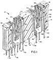
- the connector includes a dielectric housing, generally designated 14, having a plurality of terminal-receiving passages, generally designated 16.
- a plurality of standoffs 17 project from a bottom board-mounting face 18 of the housing toward the printed circuit board to space the housing from the board.
- the housing is unitarily molded of plastic material, and standoffs 17 are molded integrally therewith.
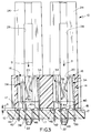
- the standoffs provide a spacing, as indicated by arrows "A" in Figure 3, to allow for cleaning processes, such as wash-through processes, to remove flux and other contaminants after the connector is soldered to printed circuit board 12.
- housing 14 defines a pair of board-receiving slots 20 for insertion thereinto of a pair of printed circuit boards in the direction of arrows "B."
- printed circuit board 12 is considered the “mother” board and the printed circuit boards (not shown) which are inserted into slots 20 are considered “daughter” boards.
- Figure 3 also shows that a plurality of mounting posts 22 project from bottom face 18 of the housing for insertion into appropriate mounting holes in circuit board 12. Like standoffs 17, mounting posts 22 are molded integrally with the housing.
- housing 14, and thereby connector 10 is considerably elongated.
- a pair of end posts 24 project upwardly from a top board-receiving face 26 of the housing, and the posts have inwardly directed grooves 28 (also see Fig. 3) for receiving the side edges of the daughter boards when they are inserted into slots 20 in the direction of arrows "B" (Fig. 3).
- Figure 2 also shows a pair of ejecting levers 30 pivotally mounted on housing 14, outside posts 24, on pivot means 32. As is known in the art, the ejecting levers facilitate ejecting the daughter boards from board-receiving slots 20 in housing 14.
- Each terminal is a stamped and formed sheet metal component and includes a semi-bellows contact beam section 36 located in housing 14, a tail section 38 projecting from bottom face 18 of the housing, and a retention section 40 between the contact beam and tail sections.
- the retention sections of the terminals are wider, in a direction transversely of passages 16, than the contact beam sections and the tail sections.
- the tail sections are provided as straight solder tails for insertion into holes 42 (Fig. 3) in circuit board 12 for soldering to circuit traces on the board and/or in the holes.
- the contact beam sections of the terminals are formed into reversely bent configurations to define spring contact arms having contact areas 44 for engaging circuit pads on opposite sides of the daughter boards inserted into board-receiving slots 20.
- the invention contemplates a unique system for reducing the height profile of a given electrical connector of the type described above.
- a plurality of retention bosses 46 are molded integrally with housing 14 in alignment with terminal-receiving passages 16 whereby the passages extend through the retention bosses.
- the retention bosses are "split" portions of housing 14 on opposite sides of terminal-receiving passages 16 and surrounding the retention sections 40 of terminals 34.
- retention bosses 46 extend downward below mounting face 18 in order to provide additional material to retain the terminal within the housing.
- At least portions of the retention sections of the terminals are located in the passages within the retention bosses. In essence, this enables the retention sections of the terminals to project downwardly below bottom face 18 of the housing and still be surrounded by sufficient plastic material of the housing to effect a retention function for the terminals between the retention sections and the housing. As a result, a longer portion of the terminals 34 may be used for the contact beam section 36 which could result in lower stresses therein.
- retention bosses 46 do not project below bottom face 18 of the housing as far as standoffs 17. Therefore, the standoffs actually engage printed circuit board 12.
- retention bosses 46 slightly shorter than standoffs 16
- retention sections 40 have been shown intentionally in Figures 1 and 3 as projecting very slightly below the retention bosses.
- the retention sections of the terminals may so project below the retention bosses, or the retention sections may be flush with the bosses, or the retention sections may be located completely within the bosses.
- Figure 4 show an alternate embodiment of the invention wherein retention bosses 50 are shown substantially identical (except slightly longer) to retention bosses 46 shown in the embodiment of Figures 1-3.
- the connector 10' in Figure 4 does not have any separate standoffs. Consequently, retention bosses 50 in connector 10' perform the dual function of providing a standoff means for the connector as well as a means within which the retention sections of the terminals are retained within the spacing between the bottom face of the housing and the printed circuit board.
Landscapes
- Coupling Device And Connection With Printed Circuit (AREA)
- Multi-Conductor Connections (AREA)
Applications Claiming Priority (2)
| Application Number | Priority Date | Filing Date | Title |
|---|---|---|---|
| US173584 | 1993-12-22 | ||
| US08/173,584 US5378175A (en) | 1993-12-22 | 1993-12-22 | Electrical connector for mounting on a printed circuit board |
Publications (3)
| Publication Number | Publication Date |
|---|---|
| EP0660460A2 true EP0660460A2 (de) | 1995-06-28 |
| EP0660460A3 EP0660460A3 (de) | 1996-11-13 |
| EP0660460B1 EP0660460B1 (de) | 2000-04-12 |
Family
ID=22632680
Family Applications (1)
| Application Number | Title | Priority Date | Filing Date |
|---|---|---|---|
| EP94119708A Expired - Lifetime EP0660460B1 (de) | 1993-12-22 | 1994-12-14 | Elektrischer Verbinder für die Montage auf einer Druckschaltungsplatte |
Country Status (6)
| Country | Link |
|---|---|
| US (1) | US5378175A (de) |
| EP (1) | EP0660460B1 (de) |
| JP (2) | JPH07211370A (de) |
| DE (1) | DE69423953T2 (de) |
| SG (1) | SG45311A1 (de) |
| TW (1) | TW403251U (de) |
Families Citing this family (14)
| Publication number | Priority date | Publication date | Assignee | Title |
|---|---|---|---|---|
| JPH08185937A (ja) * | 1994-12-28 | 1996-07-16 | Molex Inc | プリント回路基板用電気コネクタ |
| US5800214A (en) * | 1996-07-16 | 1998-09-01 | Molex Incorporated | Edge connector for a printed circuit board |
| US5800213A (en) * | 1996-07-16 | 1998-09-01 | Molex Incorporated | Edge connector for a printed circuit board |
| US5800203A (en) * | 1996-07-16 | 1998-09-01 | Molex Incorporated | Terminal retention for an electrical connector |
| US5785556A (en) * | 1996-07-16 | 1998-07-28 | Molex Incorporated | Edge connector for a printed circuit board |
| US5810623A (en) * | 1996-07-16 | 1998-09-22 | Molex Incporporated | Edge connector for a printed circuit board |
| US6135781A (en) * | 1996-07-17 | 2000-10-24 | Minnesota Mining And Manufacturing Company | Electrical interconnection system and device |
| JPH10112360A (ja) | 1996-10-08 | 1998-04-28 | Hirose Electric Co Ltd | 電気コネクタ |
| SG101926A1 (en) * | 1999-11-12 | 2004-02-27 | Molex Inc | Power connector |
| SG160263A1 (en) * | 2008-10-02 | 2010-04-29 | Molex Inc | Edge card connector |
| WO2010096567A1 (en) * | 2009-02-18 | 2010-08-26 | Molex Incorporated | Vertical connector for a printed circuit board |
| JP4948574B2 (ja) | 2009-07-24 | 2012-06-06 | 株式会社デンソー | カードエッジコネクタ及びその組付方法 |
| JP4948575B2 (ja) | 2009-07-24 | 2012-06-06 | 株式会社デンソー | カードエッジコネクタ及びその組付方法 |
| JP6609210B2 (ja) * | 2016-03-25 | 2019-11-20 | 日本圧着端子製造株式会社 | ロック機構付きコネクタ |
Family Cites Families (13)
| Publication number | Priority date | Publication date | Assignee | Title |
|---|---|---|---|---|
| US3431545A (en) * | 1967-05-18 | 1969-03-04 | United Carr Inc | Connector with bus bar |
| US3621444A (en) * | 1970-06-01 | 1971-11-16 | Elco Corp | Integrated circuit module electrical connector |
| US3697933A (en) * | 1971-04-05 | 1972-10-10 | Berg Electronics Inc | Connector block |
| US3838316A (en) * | 1973-10-09 | 1974-09-24 | Western Electric Co | Encapsulated electrical component assembly and method of fabrication |
| US4217024A (en) * | 1977-11-07 | 1980-08-12 | Burroughs Corporation | Dip socket having preloading and antiwicking features |
| US4176900A (en) * | 1977-12-23 | 1979-12-04 | Everett/Charles, Inc. | Low insertion force connector |
| DE3414323A1 (de) * | 1984-04-16 | 1985-10-24 | Siemens AG, 1000 Berlin und 8000 München | Elektrischer steckverbinder |
| DE3414343A1 (de) * | 1984-04-16 | 1985-10-17 | Siemens AG, 1000 Berlin und 8000 München | Elektrischer steckverbinder |
| US4655517A (en) * | 1985-02-15 | 1987-04-07 | Crane Electronics, Inc. | Electrical connector |
| US4663815A (en) * | 1985-06-21 | 1987-05-12 | Associated Enterprises, Inc. | A method and apparatus for surface mount compatible connector system with mechanical integrity |
| US4891023A (en) * | 1988-08-22 | 1990-01-02 | Molex Incorporated | Circuit card edge connector and terminal therefor |
| US5082459A (en) * | 1990-08-23 | 1992-01-21 | Amp Incorporated | Dual readout simm socket |
| US5137454A (en) * | 1991-05-31 | 1992-08-11 | Amp Incorporated | Surface-mount solder-tail terminal member |
-
1993
- 1993-12-22 US US08/173,584 patent/US5378175A/en not_active Expired - Fee Related
-
1994
- 1994-10-20 TW TW085204676U patent/TW403251U/zh not_active IP Right Cessation
- 1994-12-14 EP EP94119708A patent/EP0660460B1/de not_active Expired - Lifetime
- 1994-12-14 SG SG1996003272A patent/SG45311A1/en unknown
- 1994-12-14 DE DE69423953T patent/DE69423953T2/de not_active Expired - Fee Related
- 1994-12-16 JP JP6333924A patent/JPH07211370A/ja active Pending
-
1997
- 1997-06-13 JP JP1997005595U patent/JP3044377U/ja not_active Expired - Lifetime
Also Published As
| Publication number | Publication date |
|---|---|
| JPH07211370A (ja) | 1995-08-11 |
| EP0660460A3 (de) | 1996-11-13 |
| EP0660460B1 (de) | 2000-04-12 |
| JP3044377U (ja) | 1997-12-22 |
| DE69423953T2 (de) | 2000-12-07 |
| TW403251U (en) | 2000-08-21 |
| SG45311A1 (en) | 1998-01-16 |
| US5378175A (en) | 1995-01-03 |
| DE69423953D1 (de) | 2000-05-18 |
Similar Documents
| Publication | Publication Date | Title |
|---|---|---|
| US6863572B1 (en) | Electrical connector with shock support | |
| US5848920A (en) | Fabrication of electrical terminals for edge card connectors | |
| EP0567007B1 (de) | Elektrischer Verbinder zur Oberflächenmontage | |
| US5810623A (en) | Edge connector for a printed circuit board | |
| EP0449570B1 (de) | Mehrstiftiger elektrischer Verbinder mit Anschlussstiften | |
| EP0706240A1 (de) | Elektrische Zwischenverbinder für zwei Leiterplatten | |
| EP0564955A2 (de) | Randverbinder für eine Leiterplatte | |
| US20060063432A1 (en) | Shielded electrical connector assembly | |
| EP0552622A1 (de) | Oberflächenmontierte elektrische Verbinderanordnung | |
| US6068514A (en) | Surface mount electrical connector | |
| US5378175A (en) | Electrical connector for mounting on a printed circuit board | |
| EP0697755A2 (de) | Elektrischer Verbinder für Leiterplatten | |
| US20030228809A1 (en) | Terminals for an electrical socket | |
| EP0613217A1 (de) | Haltesystem für leiterplattemontierte elektrische Verbinder | |
| US5785556A (en) | Edge connector for a printed circuit board | |
| GB2296829A (en) | Printed circuit board connector | |
| EP0567006A1 (de) | Steckverbinder zusammenwirkend mit dem Rand von gedruckten Schaltungen oder ähnlichen Vorrichtungen | |
| US5997312A (en) | Grounding contact for high speed, high density connector | |
| EP0650643A1 (de) | Kartenverbinder mit flacher rückseite | |
| EP0487866A2 (de) | Elektrische Verbinderanordung zum Montieren auf gedruckter Leiterplatte | |
| US6692273B1 (en) | Straddle mount connector | |
| US6749445B1 (en) | Electrical connector with spacer | |
| US7179095B1 (en) | Matrix board-to-board connector assembly | |
| US6345992B1 (en) | Electrical connector for mounting on a printed circuit board and including a terminal tail aligner | |
| US6190183B1 (en) | Electrical connector |
Legal Events
| Date | Code | Title | Description |
|---|---|---|---|
| PUAI | Public reference made under article 153(3) epc to a published international application that has entered the european phase |
Free format text: ORIGINAL CODE: 0009012 |
|
| AK | Designated contracting states |
Kind code of ref document: A2 Designated state(s): DE FR GB IT |
|
| PUAL | Search report despatched |
Free format text: ORIGINAL CODE: 0009013 |
|
| AK | Designated contracting states |
Kind code of ref document: A3 Designated state(s): DE FR GB IT |
|
| 17P | Request for examination filed |
Effective date: 19970502 |
|
| 17Q | First examination report despatched |
Effective date: 19980218 |
|
| GRAG | Despatch of communication of intention to grant |
Free format text: ORIGINAL CODE: EPIDOS AGRA |
|
| GRAG | Despatch of communication of intention to grant |
Free format text: ORIGINAL CODE: EPIDOS AGRA |
|
| GRAH | Despatch of communication of intention to grant a patent |
Free format text: ORIGINAL CODE: EPIDOS IGRA |
|
| ITF | It: translation for a ep patent filed | ||
| GRAH | Despatch of communication of intention to grant a patent |
Free format text: ORIGINAL CODE: EPIDOS IGRA |
|
| GRAA | (expected) grant |
Free format text: ORIGINAL CODE: 0009210 |
|
| AK | Designated contracting states |
Kind code of ref document: B1 Designated state(s): DE FR GB IT |
|
| RIC1 | Information provided on ipc code assigned before grant |
Free format text: 7H 01R 12/16 A, 7H 01R 13/405 B, 7H 01R 12/22 B, 7H 01R 13/41 B |
|
| REF | Corresponds to: |
Ref document number: 69423953 Country of ref document: DE Date of ref document: 20000518 |
|
| ET | Fr: translation filed | ||
| PGFP | Annual fee paid to national office [announced via postgrant information from national office to epo] |
Ref country code: GB Payment date: 20001107 Year of fee payment: 7 |
|
| PGFP | Annual fee paid to national office [announced via postgrant information from national office to epo] |
Ref country code: FR Payment date: 20001204 Year of fee payment: 7 |
|
| PGFP | Annual fee paid to national office [announced via postgrant information from national office to epo] |
Ref country code: DE Payment date: 20001222 Year of fee payment: 7 |
|
| PLBE | No opposition filed within time limit |
Free format text: ORIGINAL CODE: 0009261 |
|
| STAA | Information on the status of an ep patent application or granted ep patent |
Free format text: STATUS: NO OPPOSITION FILED WITHIN TIME LIMIT |
|
| 26N | No opposition filed | ||
| PG25 | Lapsed in a contracting state [announced via postgrant information from national office to epo] |
Ref country code: GB Free format text: LAPSE BECAUSE OF NON-PAYMENT OF DUE FEES Effective date: 20011214 |
|
| REG | Reference to a national code |
Ref country code: GB Ref legal event code: IF02 |
|
| PG25 | Lapsed in a contracting state [announced via postgrant information from national office to epo] |
Ref country code: DE Free format text: LAPSE BECAUSE OF NON-PAYMENT OF DUE FEES Effective date: 20020702 |
|
| GBPC | Gb: european patent ceased through non-payment of renewal fee |
Effective date: 20011214 |
|
| PG25 | Lapsed in a contracting state [announced via postgrant information from national office to epo] |
Ref country code: FR Free format text: LAPSE BECAUSE OF NON-PAYMENT OF DUE FEES Effective date: 20020830 |
|
| REG | Reference to a national code |
Ref country code: FR Ref legal event code: ST |
|
| PG25 | Lapsed in a contracting state [announced via postgrant information from national office to epo] |
Ref country code: IT Free format text: LAPSE BECAUSE OF NON-PAYMENT OF DUE FEES Effective date: 20051214 |