EP0660477B1 - Prise murale de raccordement pour système de câblage optique d'immeuble - Google Patents
Prise murale de raccordement pour système de câblage optique d'immeuble Download PDFInfo
- Publication number
- EP0660477B1 EP0660477B1 EP94400992A EP94400992A EP0660477B1 EP 0660477 B1 EP0660477 B1 EP 0660477B1 EP 94400992 A EP94400992 A EP 94400992A EP 94400992 A EP94400992 A EP 94400992A EP 0660477 B1 EP0660477 B1 EP 0660477B1
- Authority
- EP
- European Patent Office
- Prior art keywords
- receptacle
- cover
- cords
- wall
- optical
- Prior art date
- Legal status (The legal status is an assumption and is not a legal conclusion. Google has not performed a legal analysis and makes no representation as to the accuracy of the status listed.)
- Expired - Lifetime
Links
Images



Classifications
-
- H—ELECTRICITY
- H02—GENERATION; CONVERSION OR DISTRIBUTION OF ELECTRIC POWER
- H02G—INSTALLATION OF ELECTRIC CABLES OR LINES, OR OF COMBINED OPTICAL AND ELECTRIC CABLES OR LINES
- H02G3/00—Installations of electric cables or lines or protective tubing therefor in or on buildings, equivalent structures or vehicles
- H02G3/02—Details
- H02G3/08—Distribution boxes; Connection or junction boxes
- H02G3/12—Distribution boxes; Connection or junction boxes for flush mounting
- H02G3/128—Distribution boxes; Connection or junction boxes for flush mounting in plinths, channels, raceways or similar
-
- G—PHYSICS
- G02—OPTICS
- G02B—OPTICAL ELEMENTS, SYSTEMS OR APPARATUS
- G02B6/00—Light guides; Structural details of arrangements comprising light guides and other optical elements, e.g. couplings
- G02B6/24—Coupling light guides
- G02B6/36—Mechanical coupling means
- G02B6/38—Mechanical coupling means having fibre to fibre mating means
- G02B6/3807—Dismountable connectors, i.e. comprising plugs
- G02B6/3897—Connectors fixed to housings, casing, frames or circuit boards
-
- G—PHYSICS
- G02—OPTICS
- G02B—OPTICAL ELEMENTS, SYSTEMS OR APPARATUS
- G02B6/00—Light guides; Structural details of arrangements comprising light guides and other optical elements, e.g. couplings
- G02B6/44—Mechanical structures for providing tensile strength and external protection for fibres, e.g. optical transmission cables
- G02B6/4439—Auxiliary devices
- G02B6/444—Systems or boxes with surplus lengths
- G02B6/4453—Cassettes
- G02B6/4455—Cassettes characterised by the way of extraction or insertion of the cassette in the distribution frame, e.g. pivoting, sliding, rotating or gliding
-
- G—PHYSICS
- G02—OPTICS
- G02B—OPTICAL ELEMENTS, SYSTEMS OR APPARATUS
- G02B6/00—Light guides; Structural details of arrangements comprising light guides and other optical elements, e.g. couplings
- G02B6/46—Processes or apparatus adapted for installing or repairing optical fibres or optical cables
- G02B6/47—Installation in buildings
- G02B6/475—Mechanical aspects of installing cables in ducts or the like for buildings
-
- G—PHYSICS
- G02—OPTICS
- G02B—OPTICAL ELEMENTS, SYSTEMS OR APPARATUS
- G02B6/00—Light guides; Structural details of arrangements comprising light guides and other optical elements, e.g. couplings
- G02B6/46—Processes or apparatus adapted for installing or repairing optical fibres or optical cables
- G02B6/50—Underground or underwater installation; Installation through tubing, conduits or ducts
- G02B6/501—Underground or underwater installation; Installation through tubing, conduits or ducts underground installation of connection boxes
Definitions
- the present invention relates to a connecting wall socket for building optical wiring system. So it's more particularly applicable to local networks whose support for transmission is preinstalled in all offices of a building industrial or commercial type, in which the company that occupies it, is equipped with a clean local network which makes it possible to make communicate with each other a plurality of computer terminals (word processor, desktop, etc.) that are installed in each of the building's offices.
- a data transmission network consists of a plurality of units generally called terminals or stations. These the latter communicate with each other through a system of transmission having a physical transmission medium which is made up either by two pairs of telephone wires, or by a cable coaxial, or by fiber optic cables.
- Local area networks are transmission networks limited to one enclosure limited in area (building, factory, campus, hospital, etc.) where the distances between stations range from a few meters, or tens of meters to a few kilometers.
- this local network is located in a building, it is more and more frequently prewired. That means that the set of physical transmission links of this network are previously installed in the building, before users of this building does not occupy the various premises of this one.
- a pre-wired building includes a distributor general and a plurality of sub-distributors.
- the sub-distributors are the basic elements of the cabling system. It is towards them that converge all local IT or office connections and those of the switched network (telephone) serving all offices located within a radius of two hundred meters around the sub-distributor. The function of it carried out in the room where it is located is brewing. This mixing makes it possible to create the different connections that we need to from the pre-wiring of the building. It is generally at the level of sub-distributor that interconnects with class networks to which the building's local network is linked.
- the sub-distributor therefore receives gateways with other networks and also includes repeaters for the building network and concentrators. Between the sub-distributors and the offices are installed physical transmission links. It is obvious that several sub-distributors can be linked together to the general distributor.
- optical fibers More and more frequently, physical transmission links are made up of optical fibers, which allow extremely high transmission rates of up to one or more several hundred megabits Mbits / s and this by limiting as much as possible losses online.
- Pre-wired building networks using any of physical transmission media listed above, for example described in more detail in the company's sales brochures BULL relating to the BULL CABLING SYSTEM (BCS), this cable network being marketed by it.
- BCS BULL CABLING SYSTEM
- optical access point wall When the local network uses a transmission medium formed of fiber optic cables, we're dealing with optical wall outlets of connection (we also use the expression “optical access point wall”).
- optical pre-wiring of buildings does not practically only concerns the main wiring frame and does not not extend to the office level for reasons of need of cost of this pre-wiring.
- a number of manufacturers and customers are interested in connection wall sockets and we can think that in the following years, the technique of development of optical wall connection sockets will know more and more successful.
- the socket mural must have a standard format, i.e. have the shape of a 50 x 50 mm or possibly 45 x 45 mm mosaic which will be the standard used in the coming years.
- taking wall connection optic must be able to accept all types of connector.
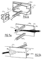
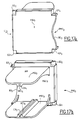
- optical wall connection sockets exist as follows, described in relation with Figures 1a and 1b.
- a wall outlet of a first PM 1 type which consists of a MOS 1 mosaic, of rectangular parallelepiped shape fixed to the plinth PL of the wall, the latter not being represented for reasons of simplicity of the drawing.
- the PM 1 socket also includes inside the mosaic two connection plugs F 1 , F 2 perpendicular to the front face FAV 1 of the mosaic, front face whose plane is parallel to that of the wall.
- the connection plugs F 1 and F 2 have an oblong shape and it is by abuse of language that we consider that they are perpendicular to the front face FAV 1 when in fact it is their axis of longitudinal symmetry perpendicular to the surface of the wall which is perpendicular to this front face.
- This same figure 1a shows two cords of optical fibers C 1 , C 2 connected respectively to the two plugs F 1 and F 2 .
- the two incoming cords as shown in this same figure, parallel to the wall and to the surface of the PLA floor, must be bent to be connected to the two plugs F 1 and F 2 over an extremely short distance, so that these cords C 1 and C 2 have a non-negligible radius of curvature R. Therefore, it is difficult to coil the cable inside the plinth in the vicinity of the plugs F 1 and F 2 .
- the terminal connection cables are connected on site.
- FIG. 1b shows a PM 2 wall outlet consisting of a MOS 2 mosaic FAV front panel 2 having the same rectangular parallelepiped shape as MOS 1 and fixed in the same way on the plinth PL.
- This PM 2 wall outlet has two connection plugs F 3 and F 4 which are perpendicular to the surface of the PLA floor and therefore face downwards.
- connection cords C 3 and C 4 connected to the plugs F 3 and we can observe the presence of a significant radius of curvature R which is made necessary to allow the two cords to be connected to two sockets.
- the drawback of the PM2 socket is therefore the same here as for the PM 1 socket, namely difficulty in coiling the cable to connect it to the two connection plugs F 3 , F 4 .
- connection plugs oriented towards the bottom of the mosaic avoids picking up any dust which is located in large numbers at the level of the office floor.
- the PM 1 and PM 2 sockets practically require pre-wiring and preconnection (with the plugs F 1 -F 2 or F 3 -F 4 ). This supposes that the problem of the radius of curvature or of coiling of the fiber is resolved.
- the present invention makes it possible to solve these problems by satisfying all the characteristics and qualities set out above.
- FIGS 2, 3, 4 and 5 show the various essential constituent elements of the optical wall socket according to the invention, which correspond respectively to the first and to the second embodiment of the socket according to the invention, namely PMI 1 and PMI 2 .
- the first embodiment PMI 1 is formed by the combination of RI receptacle shown in Figures 2a and 2b, the cache Cl 1 and SCI connector holder 1 shown in Figs 3a, 3b, and 3c and with Figure 4 .
- the second embodiment PMI 2 is formed by the association of the receptacle RI shown in FIGS. 2a and 2b and of the cover CI2 shown in FIGS. 5a and 5b.
- receptacle RI shown in Figure 2 This is shaped rectangular parallelepiped and its rear face FAR is the one by which the RI receptacle is fixed to the plinth of the wall, which is identical to the plinth PL shown in Figures 1a and 1b.
- the back side FAR is fixed by any suitable means on this plinth, for example by embedding or by any other means of fixing, for example by screwing.
- the front face FAV of the receptacle RI is that by which one or the other of the two covers CI 1 and CI 2 shown in FIGS. 3 and 4 on the one hand and 5 on the other hand is introduced.
- the FAV front face is closed in whole or in part by the main face of one or the other of the two aforementioned covers (see below).
- the receptacle RI comprises, arranged on these lower and upper faces, inside the receptacle, three pairs of slides, namely the pair GI 1 and GI 4 , the pair GI 2 and GI 5 , the pair GI 3 and GI 6 .
- the three slides GI 1 , GI 2 , GI 3 are arranged on the lower face of the receptacle, while the slides G 4 to G 6 are arranged on the upper face. It is clear that inside each pair of slides, the two slides that compose it face each other. We can also say that they are opposite each other. Thus, the GI 1 slide is opposite the GI 4 slide, GI 2 is opposite GI 5 and GI 3 is opposite GI 6 . All of these slides are female slides.
- the GI 2 -GI 5 slides are the central slides, while the other two pairs are the side slides.
- the central slides are perpendicular to the rear face (their longitudinal axis of symmetry is perpendicular to this rear face) while the lateral slides make an angle ⁇ with the central slides (their longitudinal axis of symmetry makes an angle ⁇ with the axis of longitudinal symmetry of the central slides).
- This angle ⁇ is particularly highlighted in Figure 2b which is a top view of the lower slides GI 1 to GI 3 , seen from the rear face FAR.
- the section of the slides can be of any shape.
- Figures 2a and 2b show them with a rectangular section. It is quite obvious that one calls section of the slides the central part of this one which is hollow. This section is called S.
- the lateral faces FL 1 and FL 2 perpendicular to the plinth PL are widely open, that is to say that they comprise in their central part a rectangular recess of width L which can allow the passage of optical fiber cords.
- This cover CI 1 comprises a rectangular front part PAV 1 the dimensions of which are practically those of the front face FAV of the receptacle RI.
- the dimension of this front part PAV 1 is slightly less by a fraction of a tenth of a millimeter than the dimension of the front face FAV so as to allow it to be inserted inside the receptacle. It can in some cases also constitute a hat-type closure, if it is slightly larger than the receptacle.
- the cover CI 1 further comprises in its lower part and in its upper part, arranged substantially in the plane of symmetry of the front part PAV 1 , (plane of symmetry which is perpendicular to the plane of the plinth when the cover is inserted in the receptacle), two male slides, namely a lower male slide GMI 1 and an upper male slide GMI 2 intended to be inserted in section S of any one of the three pairs of female slides GI 1 -GI 4 , GI 2 -GI 5 , GI 3 -GI 6 .
- each of the slides GMI 1 and GMI 2 respectively comprises a male groove RMI 1 and RMI 2 .
- the section of these male grooves is shown rectangular in Figures 3a, 3b, and 4.
- This rectangular section has the same area as the rectangular section S of the female grooves of the female slides shown in Figures 2a and 2b, to allow the RMI male grooves 1 and RMI 2 to be inserted into the female grooves of the pairs of slideways of the receptacle.
- the male grooves RMI 1 and RMI 2 are respectively arranged in the lower part and in the upper part of the corresponding male slides GMI 1 and GMI 2 .
- each of the male slides GMI 1 and GMI 2 comprises female grooves RFI 1 and RFI 2 .
- RFI 1 and RFI 2 are located respectively in the upper part of GMI 1 and in the lower part of GMI 2 .
- the female groove RFI 1 is located above the groove RMI 1 .
- the male groove RMI 2 is located above the female groove RFI 2 .
- a dust cover CP integral with PAV 1 .
- the two female grooves RFI 1 and RFI 2 are intended to receive the connector support SCI 1 , which is inserted by sliding inside them.
- This SCI 1 connector support is shown in Figure 3c. It comprises a rectangular SRI support, for example made of plastic, and means for connecting the optical fiber cords, constituted for example by two standard ST type fittings, designated by RCI 1 and RCl 2 . It is obvious that any type of preferably standardized optical connector can be installed as a connection means on this connector support SCI 1 .
- the connector support SCI 1 is a removable part and can be inserted by sliding as indicated in FIG. 4, from back to front, perpendicular to the plane of CI 1 .
- the support is introduced into the two female grooves RFI 1 and RFI 2 .
- the first embodiment of the CI cover 1 can occupy two positions:
- the cover CI 1 is introduced into one or the other of the pairs of lateral guides GI 1 -GI 4 or GI 3 -GI 6 , depending on whether an output of the cords is desired towards the terminal on the left or on the right, or of course following the direction of arrival of the optical fiber cable coming from the sub-distributor. In this case, the cover then has an opening allowing the cord to exit, horizontally and substantially parallel to the plinth PL.
- This second embodiment comprises a receptacle RI identical to that of the first embodiment and which therefore bears the same name, and a cover CI 2 .
- the latter comprises a front part PAV 2 on which the male slides GMI 3 and GMI 4 are fixed, the structure of which is completely identical to that of the male slides GMI 1 and GMI 2 shown in FIGS. 3 and 4.
- the front part PAV 2 includes a boss BO 2 inside which we pass one or two cords or two cables (or 4 optical fibers) as we can better see for example in FIG. 6b which is a top view of the boss BO 2 inside which the two cords CO 5 and CO 6 are passed. These two cords are embedded by a flexible seal which holds them in place inside the BO 2 embossing.
- FIG. 6c shows the embossing comprising the two cords CO 5 and CO 6 seen from below, with the fixing system of these SFI 2 .
- Figure 6a there is shown an overview showing the two cords CO 5 and CO 6 coiled in the plinth PL on the right side of the figure and passing through the boss BO 2 , the cord being inside the embossment parallel to the wall and the floor, as indicated by arrow A, the PMI 2 wall outlet being shown as a 3/4 perspective view mounted on the PL plinth.
- the third embodiment of the wall socket according to the invention comprises an receptacle RI 3 and a cover CI 3 .
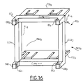
- the receptacle is shown in Figure 16 while the cover is shown in Figures 17a and 17b, Figure 17a being a 3/4 front view while Figure 17b is a rear 3/4 view.
- the receptacle RI 3 no longer has slides like the receptacle RI common to the first and to the second embodiment PMI 1 and PMI 2 .
- the upper and lower horizontal faces FSI 3 and FII 3 of the receptacle RI 3 have, as can be seen in this same figure 16, grooves which are simply used to facilitate the mounting of the receptacle inside the wall plinth where it's going to be fixed. There is therefore no need to further describe these grooves or the method of fixing the receptacle inside the plinth which can be done in known manner and which in any case does not constitute one of the characteristics of the invention.
- the receptacle RI 3 has a front face FAV 3 which comprises a rectangular frame comprising two vertical lateral sides CLV 1 and CLV 2 and two horizontal lateral sides CLH 1 and CLH 2 .
- the inner part of this frame located inside the lateral sides is intended either to be completely closed by the cover CI 3 when the cover is in the waiting position (see below), or to make a dihedral of angle ⁇ with the cover so as to allow the optical cords to pass between the front face FAV 3 and the surface of the cover, in a manner strictly identical to that which is shown in FIG. 7.
- the receptacle RI 3 also includes vertical lateral faces FL 3 and FL 4 (perpendicular to FAV 3 ) through which the optical cords can also pass, in the same manner as in FIG. 7 for example.
- the vertical lateral sides CLV 1 and CLV 2 have protruding projections in their lower part and in their upper part relative to the plane thereof. These projecting overflows are called DB 1 (lower part) and DB 2 (upper part) for the vertical lateral side CLV 1 , and are called DB 3 and DB 4 for the lower and upper parts of the vertical lateral side CLV 2 .
- Each of the protruding overhangs DB 1 to DB 4 comprises an embedding, namely respectively EC 1 to EC 4 .
- Each of these recesses is made inside the volume formed by each of these overflows DP 1 to DP 4 . We can see in Figure 16 that the EC 1 and EC 3 recesses face each other, as do the EC 2 and EC 4 recesses.
- FIG. 17A shows the CI cover 3 .
- the latter has a front portion PAV 3 of substantially rectangular shape, which may include a boss BO 3 identical to the boss of the cover CI 2 shown for example in Figure 5a or 5b.
- CI 3 has on its left lateral side in FIG. 17A (right lateral side in FIG. 17b), in its lower part and in its upper part, lugs EG 1 , EG 2 intended to be inserted inside EC 1 and EC 2 recesses in Figure 16.
- lugs EG 1 , EG 2 intended to be inserted inside EC 1 and EC 2 recesses in Figure 16.
- These EG 1 and EG 2 pins can also be inserted into the EC 3 and EC 4 recesses.
- the wall socket thus formed has a vertical hinge around which the CI cover 3 can pivot relative to the FAV 3 face so that this last make a dihedral of angle ⁇ with it, exactly in the same way as indicated in figure 7.
- the optical cords pass between the front face FAV 3 of the receptacle RI 3 and the front part PAV 3 of the CI cover 3 .
- the front part PAV3 can be pressed onto the front face FAV 3 and in this case, the cover CI 3 completely closes the receptacle RI 3 .
- the PMI 3 wall outlet is then in what can be called a waiting position, more specifically described below.
- the PAV part 3 of the cover CI 3 comprises in its lower part and in its upper part shoulders EP 3 and EP 4 which are intended to come into contact with overflows DB 4 (in the lower part thereof) and DB 3 (in the upper part thereof in FIG. 16) when the cover CI 3 comes to close the receptacle RI 3 .
- the cover CI 3 has upper and lower faces PSI 3 and PII 3 , which are horizontal and which are intended to come into contact with the lower and upper parts respectively of the upper faces FSI 3 and lower FII 3 of the receptacle RI 3 .
- the upper part PSI 3 has in its lower part in the center thereof a U-shaped angle iron CN 1.
- the lower part PII 3 has in its central part and in its upper part an angle iron CN 2 , also U-shaped.
- the two angles CN 1 and CN 2 face each other and also have female grooves RFI 5 and RFI 6 . Inside these female grooves can be inserted the connector support SCI 1 shown in FIG. 4.
- the covers CI 1 , CI 2 and CI 3 can occupy two positions which are as follows:
- CI 2 is introduced into the central slides GI 2 -GI 5 and therefore completely closes the receptacle. It should be noted that in all cases of use CI 2 can also receive the connector support SCI 1 .
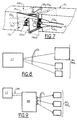
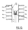
- Figures 8, 9, 10 show schematically how the technical rooms are connected including the sub-distributors to the different optical wall sockets located in one or more offices.
- a technical room LT connected to a set of offices BU i in Figure 8 and BU j in Figure 9.
- the technical room LT is connected to a plurality of offices BU 1 to BU 9 , these offices being assumed to be distributed on either side of a corridor CL, the technical room being supposed to be represented in the middle of the corridor.
- the technical room is in a first embodiment connected by a set of bi-fiber cords CO i (in Figure 8 we have shown 3 cords, but there may be much more) at the office BU i in which a set of wall sockets PMl i are located.
- a set of wall sockets PMl i in which a set of wall sockets PMl i are located.
- FIG. 9 a second mode of connection can be seen between the technical room LT and the set of offices BU j provided with a set of wall sockets PMl j , according to the invention.
- the LT technical room is first connected to a BP proximity box via a CMF multi-fiber cable.
- the proximity box BP is itself connected via a set of bi-fiber cords CO j analogous to CO i to all the offices BU j provided with PMI j wall sockets.
- the technical room LT is shown connected via bi-fiber cords, similar to CO i or CO j to the various offices.
- These cords CO i and CO j are arranged inside a false ceiling in the corridor CL and from this false ceiling, they are redistributed inside each of the offices BU 1 to BU 9 .
- the fiber optic link between the LT technical room and one or other of the PMI i or PMI j wall sockets can be done by pre-wiring or post-wiring with or without mounting of connectors at the time of installation (this is that is to say with or without the presence of the connector support of the SCI type 1 ).
- the use of a proximity box reduces the distance between the sub-distributor contained in the technical room and the wall sockets. In this case, it is then possible to use between the proximity box BP and the various wall outlets of the preconnected cords directly in manufacturing at the factory and therefore more reliable.
- FIG. 11 shows a pre-wired connection, on hold.
- the cover CI 1 being equipped with its connector support SCI 1 closes the receptacle RI of the wall socket here designated by PMIi.
- the connector SCI 1 is connected by the cable CO i to the technical room LT.
- FIG 12. This shows a pre-wired or post-wired connection in the position of use, the cover CI 1 being used and allowing the exit to the right of the cord CO k going to the terminal T, the technical room LT being connected as in figure 11 to the PMI i wall socket, using the CO i cable.
- the cover CI 1 being used and allowing the exit to the right of the cord CO k going to the terminal T, the technical room LT being connected as in figure 11 to the PMI i wall socket, using the CO i cable.
- FIG. 13 This figure corresponds to what is shown in Figure 9, that is to say that the technical room LT is connected by a multi-fiber cable CMF to a proximity box BP.
- the wall socket PMI j is on standby and the cover of the socket, whether it is the cover CI 1 or CI 2 , closes the receptacle RI.
- FIG. 14 where it has been assumed that the wall outlet PM1 j is of the first embodiment type, that is to say with a cover of type CI 1 .
- a connection cord CO j is used between the proximity box BP and the wall outlet PMl j and the terminal T is connected to this wall outlet via a cord CO k .
- the two cords CO j and CO k are connected to a connector support of the SCI 1 type.
- the CI type cover 1 is in the use position allowing the cord to exit, for example to the right. In the case of Figure 14, it is either pre or post-wiring.
- the technical room LT is always connected to a proximity box BP by means of a multi-fiber cord CMF.
- the proximity box is connected directly to the terminal T by the cord CO j .
- the cover of type CI 2 which completely closes the receptacle RI by letting the cord CO j pass through the boss of type BO 2 .
- the wall outlet is designated by PMI j .
- a CO j cord is used which is prewired directly in the manufacturing plant, resulting in a gain in cost, reliability and speed of installation and even in speed of disconnection.
Landscapes
- Physics & Mathematics (AREA)
- General Physics & Mathematics (AREA)
- Optics & Photonics (AREA)
- Engineering & Computer Science (AREA)
- Civil Engineering (AREA)
- Structural Engineering (AREA)
- Architecture (AREA)
- Light Guides In General And Applications Therefor (AREA)
- Mechanical Coupling Of Light Guides (AREA)
- Optical Couplings Of Light Guides (AREA)
- Connector Housings Or Holding Contact Members (AREA)
Description
- avoir un coût relativement faible,
- pouvoir être précâblée ou postcâblée,
- Dans le cas d'un postcâblage :
- pouvoir être installée à la demande,
- pouvoir être déplacée,
- pouvoir être installée très rapidement, ou au contraire démontée,
- ne pas nécessiter d'outillage particulier pour l'installer,
- pouvoir permettre de lover très simplement une certaine longueur de câble optique sans contrainte abusive sur le câble, et ce à l'intérieur si possible de la plinthe : en particulier il faut tenir compte du rayon de courbure maximum que peut subir un cordon de fibre optique pour être lové sans qu'il soit détérioré,
- enfin avoir un coût faible.
- Dans le cas d'un précâblage les qualités nécessaires à une prise
optique murale de raccordement sont les suivantes :
- permettre à un utilisateur de pouvoir être connecté rapidement,
- permettre de lover de manière simple une certaine longueur de câble sans contrainte abusive sur celui-ci,
- avoir un trés faible coût avant utilisation, le point d'accès en précâblage étant généralisé.
- elles n'acceptent en général qu'un seul type de connectique,
- le sens de sortie des cordons d'utilisation allant vers le terminal ou la station est fixe,
- la prise murale installée, en cas de précablage est onéreuse et ce d'autant plus si elle reste inutilisée par la suite car elle est équipée systématiquement de ses connecteurs,
- enfin, elle ne possède qu'une seule fonction : connecter la station ou terminal au câble d'arrivée du sous-répartiteur.
- un réceptacle fixé dans une plinthe murale dans laquelle sont insérés des cordons optiques support de l'information à transmettre sur le réseau local de l'immeuble comportant une pluralité de terminaux,
- et des moyens de raccordement des cordons au terminal associé à la prise,
- un cache amovible associé à un support amovible de connecteurs permettant la connexion optique des dits cordons,
- le cache pouvant occuper une position d'attente dans laquelle il ferme la face avant du réceptacle, d'une part, ou une position d'utilisation où le plan du cache forme un dièdre avec cette face avant, d'autre part, les cordons sortant alors latéralement par rapport au réceptacle de part et d'autre de celui-ci,
- la prise comportant des premiers moyens de positionnement coopérant avec des seconds moyens de positionnement appartenant au réceptacle de manière à faire passer le cache de la position d'attente à la position d'utilisation, et étant caractérisée comme revendiqué à la revendication 1.
- la figure 1, composée des figures 1a et 1b montre deux exemples de prise murale de raccordements selon l'art antérieur,
- la figure 2, composée des figures 2a et 2b montre le réceptacle de la prise murale selon l'invention, destiné à recevoir le cache et le support du connecteur,
- la figure 3 composée des figures 3a, 3b, 3 c, qui sont des vues en perspectives de 3/4, montrent les différents éléments constitutifs d'un premier exemple de réalisation du cache destiné à être insérer dans le réceptacle,
- la figure 4 est une vue de 3/4 en perspective montrant comment s'insère le support de connecteur à l'intérieur du premier modèle de réalisation du cache appartenant à une prise murale selon l'invention. La figure montre aussi, ne figurant pas sur les autres figures représentant le cache, le système de protection anti-poussière qui protège la connectique optique lorsque le cache est en position d'utilisation.
- La figure 5 composée des figures 5a et 5b montre la seconde réalisation du cache appartenant à la prise murale selon l'invention, la figure 5a étant une vue de 3/4 arrière en perspective et la figure 5b étant une vue de 3/4 avant en perspective.
- La figure 6, composée des figures 6a, 6b et 6c montre plus en détail la face avant du second modèle de réalisation de la prise murale de raccordement selon l'invention,
- La figure 7 montre vue de 3/4 en perspective le premier modèle de réalisation de la prise murale selon l'invention, en position d'utilisation,
- Les figures 8 et 9 montrent deux façons de réaliser des liaisons entre un local technique comportant un sous-répartiteur et différents points d'accès disposés à l'intérieur d'un bureau,
- La figure 10 est un autre schéma extrêmement simplifié montrant comment sont reliés les répartiteurs aux différents bureaux,
- Les figures 11 à 15 illustrent différents cas d'emplois de l'un ou l'autre des deux modèles de réalisation de la prise murale de raccordement selon l'invention.
- Les figures 16 et 17, cette dernière étant composée des figures 17a, 17b, montrent un troisième mode de réalisation de la prise murale selon l'invention.
- possibilité avec le cache de type CI2 d'économiser une connexion,
- possibilité d'arrivée ou de départ du cordon de liaison vers la prise murale soit à droite, soit à gauche de celle-ci (voir figure 7, par exemple),
- sens d'arrivée et de sortie du cordon horizontal parallèlement à la plinthe, ce qui assure une meilleure protection du cordon et offre la meilleure solution en ce qui concerne le problème du rayon de courbure R du cordon optique, en facilitant le lovage de ce dernier,
- prise murale à très faible coût,
- facilité d'installation qui ne nécessite aucun outil spécialisé,
- réponse à tous les cas possible d'utilisation avec n'importe quel type de connecteur,
- utilisation possible des prises murales selon l'invention soit en pré soit en postcâblage.
Claims (7)
- Prise murale de raccordement (PMI1 à PMI3) pour système de câblage optique d'un immeuble, comportant :un réceptacle (RI, RI3) fixé dans une plinthe (PL) murale dans laquelle sont insérés des cordons optiques (COi, COj, CO1 à CO4) support de l'information à transmettre sur le réseau local de l'immeuble comportant une pluralité de terminaux,des moyens de raccordement des cordons (CI1, CI2) au terminal associé à la prise,les moyens de raccordement comprenant :un cache amovible (CI1 à CI3) associé à un support amovible de connecteurs (SCI1) permettant la connexion optique des dits cordons,le cache pouvant occuper une position d'attente dans laquelle il ferme la face avant du réceptacle, d'une part, ou une position d'utilisation où le plan du cache forme un dièdre avec cette face avant, d'autre part, les cordons sortant alors latéralement par rapport au réceptacle de part et d'autre de celui-ci,la prise comportant des premiers moyens de positionnement (GMI1-GMI2, EG1-EG2) coopérant avec des seconds moyens de positionnement appartenant au réceptacle (GI1 à GI6, EC1-EC, EC3-EC4) de manière à faire passer le cache de la position d'attente à la position d'utilisation,et étant caractérisée en ce que les faces latérales (FL1, FL2) du réceptacle qui sont perpendiculaires à la plinthe (PL) comprennent, dans leur partie centrale, un évidement rectangulaire permettant le passage des fibres optiques parallèlement à la pinthe (PL),et en ce que le support amovible (SCI1) comprend des moyens de connexion (RCI1, RCI2) des fibres optiques et est agencé pour être monté perpendiculairement à la plinthe ce qui permet aux fibres d'être parallèles à la plinthe de part et d'autre de celle-ci.
- Prise murale selon la revendication 1 caractérisé en ce que le cache amovible CI1 à C12) est destiné à être inséré dans un système de glissières (GI1-G14, GI2-GI5, GI3-GI6) disposées à l'intérieur du réceptacle (RI) sur les faces supérieure et inférieure de celui-ci, le support de connecteur (SCI1) étant destiné à être introduit par glissement à l'intérieur de rainures qui sont portées par le cache (RFI1, RFI2).
- Prise murale selon la revendication 2, caractérisée en ce que les glissières du réceptacle (RI) comprennent une première paire de glissières centrales GI2-GI5), et deux secondes paires (GI1-GI4, GI2-GI5, GI3-GI6) de glissières latérales de part et d'autre des glissières centrales, faisant chacune un angle α avec la paire de glissières centrales, les glissières d'une même paire étant en regard l'une de l'autre.
- Prise murale selon la revendication 3, caractérisée en ce que le cache amovible (CI1) comprend une partie avant (PAV1) destinée à venir fermer la face avant (FAV) du réceptacle, comportant une troisième paire de glissières (GMI1, GMI2) disposées sensiblement dans le plan de symétrie vertical qui lui est perpendiculaire, chaque glissière étant destinée à coopérer avec une glissière correspondante de la première paire ou de l'une quelconque des secondes paires, de manière à ce que le cache (CI1) soit inséré dans le receptacle (RI).
- Prise murale selon la revendication 3, caractérisée en ce que le cache amovible (CI1) comprend une partie avant (PAV2) destinée à venir fermer la face avant (FAV1) du réceptacle (RI), comportant une quatrième paire de glissières ((GMI3, GMI4) disposées sensiblement dans le plan de symétrie vertical qui lui est perpendiculaire, chaque glissière étant destinée à coopérer avec une glissière correspondante de la première paire ou de l'une quelconque des secondes paires, de manière à ce que le cache (CI1) soit inséré dans le réceptacle (RI), la partie avant (PAV2) comportant en outre un bosselage (BO2) à l'intérieur duquel sont fixés des cordons ou câbles optiques parallèles au mur où est fixée la prise murale, et au plancher perpendiculaire au mur.
- Prise selon l'une quelconque des revendications 2 ou 3, caractérisée en ce que le support de connecteurs (SCI1) comprend un support rectangulaire (SRI) et des moyens de connexion (RCI1, RCI2) de cordons ou câbles de fibre optique fixés sur le support, lequel est destiné à venir s'insérer dans des rainures (RFI1, RFI2) pratiquées dans l'une quelconque des seconde, troisième ou quatrième paires de glissières.
- Prise selon la revendication 1 caractérisée en ce que le réceptacle (RI3) comporte sur les deux côtés verticaux de sa face avant, dans la partie inférieure et supérieure de celle-ci, des débordements saillants par rapport au plan de celle-ci (DPI à DP4), ces derniers contenant chacun un encastrement caractérisée en ce que(EC1 à EC4), le cache (CI3) comportant dans sa partie avant, sur l'un des côtés latéraux verticaux dans la partie inférieure et dans la partie supérieure de celui-ci, un ergot (EG1, EG2), destiné à être inséré dans l'encastrement correspondant du réceptacle, la prise murale formée par le cache (CI3) et le réceptacle (RI3) possédant ainsi une charnière verticale autour de laquelle peut pivoter le cache d'un angle de valeur a de manière à permettre la sortie latérale des cordons par rapport au réceptacle de part et d'autre de celui-ci, parallèlement à la plinthe.
Applications Claiming Priority (2)
| Application Number | Priority Date | Filing Date | Title |
|---|---|---|---|
| FR9315389 | 1993-12-21 | ||
| FR9315389 | 1993-12-21 |
Publications (2)
| Publication Number | Publication Date |
|---|---|
| EP0660477A1 EP0660477A1 (fr) | 1995-06-28 |
| EP0660477B1 true EP0660477B1 (fr) | 1998-08-12 |
Family
ID=9454177
Family Applications (1)
| Application Number | Title | Priority Date | Filing Date |
|---|---|---|---|
| EP94400992A Expired - Lifetime EP0660477B1 (fr) | 1993-12-21 | 1994-05-06 | Prise murale de raccordement pour système de câblage optique d'immeuble |
Country Status (4)
| Country | Link |
|---|---|
| US (1) | US5473717A (fr) |
| EP (1) | EP0660477B1 (fr) |
| JP (1) | JP2818545B2 (fr) |
| DE (1) | DE69412444T2 (fr) |
Families Citing this family (11)
| Publication number | Priority date | Publication date | Assignee | Title |
|---|---|---|---|---|
| FR2746931B1 (fr) * | 1996-03-29 | 1998-06-19 | Soc D Fabrication Ind Et Mecan | Dispositif de raccordement, notamment pour reseau a fibres optiques |
| US6216406B1 (en) | 1997-06-09 | 2001-04-17 | Herb Hauser | Baseboard infrastructure system |
| USD443252S1 (en) | 2000-06-02 | 2001-06-05 | Corning Cable Systems Llc | Wall mount housing |
| JP4537081B2 (ja) * | 2004-01-27 | 2010-09-01 | 神保電器株式会社 | 集合住宅用光ファイバ先行配線方法及び同方法に使用する集合住宅用先行配線光接続キャビネット |
| US20080131057A1 (en) * | 2006-12-05 | 2008-06-05 | Mcgranahan Danny | Fiber optic wall outlet with slack storage |
| FR2923618B1 (fr) * | 2007-11-14 | 2010-06-04 | Nexans | Prise optique pour reseau de telecommunication |
| US9042699B2 (en) * | 2010-06-02 | 2015-05-26 | Tyco Electronics Corporation | Switch rack system |
| CA2821726C (fr) * | 2012-07-23 | 2016-02-09 | Brian William Karam | Systeme de divertissement, d'eclairage et de conditionnement d'air |
| US9885845B2 (en) * | 2015-01-15 | 2018-02-06 | Commscope, Inc. Of North Carolina | Module and assembly for fiber optic interconnections |
| US9851523B2 (en) | 2015-09-22 | 2017-12-26 | Go!Foton Holdings, Inc. | Apparatus for cable routing |
| US10310206B2 (en) | 2017-05-22 | 2019-06-04 | Go!Foton Holdings, Inc. | Apparatus for cable routing |
Family Cites Families (14)
| Publication number | Priority date | Publication date | Assignee | Title |
|---|---|---|---|---|
| US4611887A (en) * | 1983-02-24 | 1986-09-16 | Amp Incorporated | Fiber optic connector assembly and wall outlet thereof |
| US5076656A (en) * | 1984-06-08 | 1991-12-31 | Briggs Robert C | High precision optical fiber connectors |
| US4669802A (en) * | 1986-03-26 | 1987-06-02 | Amp Incorporated | Outlet for optical fiber connectors |
| EP0305338B1 (fr) * | 1987-08-28 | 1993-02-03 | Ulrich Gantenbein | Ensemble de pièces et son utilisation pour la construction de conduits et de boîtiers dans un immeuble |
| US4950184A (en) * | 1988-04-08 | 1990-08-21 | Panduit Corp. | Wall plate assembly |
| US4874904A (en) * | 1988-04-14 | 1989-10-17 | Brintec Corporation | Fiber optic faceplate assembly |
| US4960317A (en) * | 1988-08-23 | 1990-10-02 | Amp Incorporated | Wall outlet for a fiber optic connector assembly |
| DE68914574T2 (de) * | 1988-08-23 | 1994-10-13 | Whitaker Corp | Steckvorrichtung für einen faseroptischen Stecker. |
| DE3900021A1 (de) * | 1989-01-02 | 1990-10-11 | Anton Dipl Ing Hartmann | Lichtwellenleiter-steckverbindung |
| US5142597A (en) * | 1990-07-27 | 1992-08-25 | Amp Incorporated | Interconnect assembly for wall outlet |
| GB9027074D0 (en) * | 1990-12-13 | 1991-02-06 | Bicc Plc | Optical fibre termination device |
| US5265186A (en) * | 1991-11-12 | 1993-11-23 | At&T Bell Laboratories | Optical fiber distribution apparatus |
| JPH05249345A (ja) * | 1992-03-09 | 1993-09-28 | Fujitsu Ltd | 光コネクタと光アダプタの結合方法および該光アダプタの取り付け構造 |
| JP3018620U (ja) * | 1995-05-24 | 1995-11-28 | アイデック株式会社 | ベルト型バッテリーパック |
-
1994
- 1994-05-06 EP EP94400992A patent/EP0660477B1/fr not_active Expired - Lifetime
- 1994-05-06 DE DE69412444T patent/DE69412444T2/de not_active Expired - Fee Related
- 1994-07-15 US US08/275,874 patent/US5473717A/en not_active Expired - Fee Related
- 1994-12-19 JP JP6314828A patent/JP2818545B2/ja not_active Expired - Lifetime
Also Published As
| Publication number | Publication date |
|---|---|
| US5473717A (en) | 1995-12-05 |
| JP2818545B2 (ja) | 1998-10-30 |
| DE69412444D1 (de) | 1998-09-17 |
| DE69412444T2 (de) | 1999-01-07 |
| JPH07198964A (ja) | 1995-08-01 |
| EP0660477A1 (fr) | 1995-06-28 |
Similar Documents
| Publication | Publication Date | Title |
|---|---|---|
| EP0660477B1 (fr) | Prise murale de raccordement pour système de câblage optique d'immeuble | |
| EP1315009B1 (fr) | Module de distribution et de connexion de fibres optiques destiné à un répartiteur optique | |
| US7352945B2 (en) | Outside plant enclosure with pivoting fiber trays | |
| US20110013875A1 (en) | Fiber optic enclosure with adapter bulkhead positioned beneath pivotal splice tray | |
| FR2929717A1 (fr) | Boitier optique | |
| EP1870750B1 (fr) | Cassette pour cables optiques, rail de support et ensemble d'empilage de telles cassettes | |
| FR2581767A1 (fr) | Point de branchement pour cables a fibres optiques | |
| US20120292096A1 (en) | Modular plug and play connectivity platform | |
| EP1299759A1 (fr) | Boitier de raccordement de fibres optiques a des postes de travail, pour immeubles | |
| EP2045636A1 (fr) | Prise optique pour reseau de telecommunication | |
| EP3317707A1 (fr) | Boîtier de répartition optique et ensemble | |
| EP0484243B1 (fr) | Prise courants faibles pour précâblage de bâtiment | |
| WO1997037413A1 (fr) | Dispositif de raccordement, notamment pour reseau a fibres optiques | |
| FR2923618A1 (fr) | Prise optique pour reseau de telecommunication | |
| EP1054279A1 (fr) | Boítier d'accès à une ou plusieurs fibres optiques dans un câble tendu | |
| FR2979438A1 (fr) | Dipositif de lovage, accessoire de lovage et dispositif de connexion pour fibre optique | |
| FR2581769A1 (fr) | Dispositif pour le stockage de fibres optiques | |
| WO1998047031A1 (fr) | Prise opto-electrique et ensemble de connexion opto-electrique pour le precablage de batiment | |
| EP3301491B3 (fr) | Module de connexion optique | |
| CN219392334U (zh) | 预连接型光缆分纤箱 | |
| EP1583192B1 (fr) | Armoire dotée d'ouvertures pour le passage de câbles | |
| FR2951588A1 (fr) | Socle de connexion electrique montable sur rail | |
| FR2938932A1 (fr) | Dispositif de connexion entre une fibre optique d'un reseau et un cordon d'un abonne. | |
| FR3130407A3 (fr) | Panneau à fibres optiques | |
| FR3045969A1 (fr) | Dispositif de guidage de cables orientable |
Legal Events
| Date | Code | Title | Description |
|---|---|---|---|
| PUAI | Public reference made under article 153(3) epc to a published international application that has entered the european phase |
Free format text: ORIGINAL CODE: 0009012 |
|
| 17P | Request for examination filed |
Effective date: 19941207 |
|
| AK | Designated contracting states |
Kind code of ref document: A1 Designated state(s): DE ES FR GB IT SE |
|
| 17Q | First examination report despatched |
Effective date: 19960816 |
|
| GRAG | Despatch of communication of intention to grant |
Free format text: ORIGINAL CODE: EPIDOS AGRA |
|
| GRAG | Despatch of communication of intention to grant |
Free format text: ORIGINAL CODE: EPIDOS AGRA |
|
| GRAH | Despatch of communication of intention to grant a patent |
Free format text: ORIGINAL CODE: EPIDOS IGRA |
|
| GRAH | Despatch of communication of intention to grant a patent |
Free format text: ORIGINAL CODE: EPIDOS IGRA |
|
| GRAA | (expected) grant |
Free format text: ORIGINAL CODE: 0009210 |
|
| AK | Designated contracting states |
Kind code of ref document: B1 Designated state(s): DE ES FR GB IT SE |
|
| PG25 | Lapsed in a contracting state [announced via postgrant information from national office to epo] |
Ref country code: ES Free format text: THE PATENT HAS BEEN ANNULLED BY A DECISION OF A NATIONAL AUTHORITY Effective date: 19980812 |
|
| GBT | Gb: translation of ep patent filed (gb section 77(6)(a)/1977) |
Effective date: 19980814 |
|
| ITF | It: translation for a ep patent filed | ||
| REF | Corresponds to: |
Ref document number: 69412444 Country of ref document: DE Date of ref document: 19980917 |
|
| PG25 | Lapsed in a contracting state [announced via postgrant information from national office to epo] |
Ref country code: SE Free format text: LAPSE BECAUSE OF FAILURE TO SUBMIT A TRANSLATION OF THE DESCRIPTION OR TO PAY THE FEE WITHIN THE PRESCRIBED TIME-LIMIT Effective date: 19981112 |
|
| PGFP | Annual fee paid to national office [announced via postgrant information from national office to epo] |
Ref country code: GB Payment date: 19990430 Year of fee payment: 6 |
|
| PGFP | Annual fee paid to national office [announced via postgrant information from national office to epo] |
Ref country code: FR Payment date: 19990503 Year of fee payment: 6 |
|
| PLBE | No opposition filed within time limit |
Free format text: ORIGINAL CODE: 0009261 |
|
| STAA | Information on the status of an ep patent application or granted ep patent |
Free format text: STATUS: NO OPPOSITION FILED WITHIN TIME LIMIT |
|
| PGFP | Annual fee paid to national office [announced via postgrant information from national office to epo] |
Ref country code: DE Payment date: 19990727 Year of fee payment: 6 |
|
| 26N | No opposition filed | ||
| PG25 | Lapsed in a contracting state [announced via postgrant information from national office to epo] |
Ref country code: GB Free format text: LAPSE BECAUSE OF NON-PAYMENT OF DUE FEES Effective date: 20000506 |
|
| GBPC | Gb: european patent ceased through non-payment of renewal fee |
Effective date: 20000506 |
|
| PG25 | Lapsed in a contracting state [announced via postgrant information from national office to epo] |
Ref country code: FR Free format text: LAPSE BECAUSE OF NON-PAYMENT OF DUE FEES Effective date: 20010131 |
|
| PG25 | Lapsed in a contracting state [announced via postgrant information from national office to epo] |
Ref country code: DE Free format text: LAPSE BECAUSE OF NON-PAYMENT OF DUE FEES Effective date: 20010301 |
|
| REG | Reference to a national code |
Ref country code: FR Ref legal event code: ST |
|
| PG25 | Lapsed in a contracting state [announced via postgrant information from national office to epo] |
Ref country code: IT Free format text: LAPSE BECAUSE OF NON-PAYMENT OF DUE FEES;WARNING: LAPSES OF ITALIAN PATENTS WITH EFFECTIVE DATE BEFORE 2007 MAY HAVE OCCURRED AT ANY TIME BEFORE 2007. THE CORRECT EFFECTIVE DATE MAY BE DIFFERENT FROM THE ONE RECORDED. Effective date: 20050506 |