EP0660581A2 - Bildübertragungsgerät - Google Patents
Bildübertragungsgerät Download PDFInfo
- Publication number
- EP0660581A2 EP0660581A2 EP94309490A EP94309490A EP0660581A2 EP 0660581 A2 EP0660581 A2 EP 0660581A2 EP 94309490 A EP94309490 A EP 94309490A EP 94309490 A EP94309490 A EP 94309490A EP 0660581 A2 EP0660581 A2 EP 0660581A2
- Authority
- EP
- European Patent Office
- Prior art keywords
- image
- monochromatic
- color
- mode
- entered
- Prior art date
- Legal status (The legal status is an assumption and is not a legal conclusion. Google has not performed a legal analysis and makes no representation as to the accuracy of the status listed.)
- Granted
Links
- 230000005540 biological transmission Effects 0.000 claims abstract description 95
- 238000004891 communication Methods 0.000 claims abstract description 73
- 238000003860 storage Methods 0.000 claims abstract description 10
- 238000012545 processing Methods 0.000 claims abstract description 7
- 238000000034 method Methods 0.000 claims description 31
- 230000006870 function Effects 0.000 claims description 15
- 230000000694 effects Effects 0.000 claims description 11
- 230000004044 response Effects 0.000 claims description 11
- 230000008569 process Effects 0.000 claims description 10
- 238000007906 compression Methods 0.000 claims description 5
- 230000006835 compression Effects 0.000 claims description 5
- 239000000872 buffer Substances 0.000 description 24
- 239000000976 ink Substances 0.000 description 23
- 238000010586 diagram Methods 0.000 description 12
- 238000006243 chemical reaction Methods 0.000 description 11
- 239000003550 marker Substances 0.000 description 11
- 238000012546 transfer Methods 0.000 description 8
- 238000009825 accumulation Methods 0.000 description 7
- 230000008859 change Effects 0.000 description 6
- 230000006866 deterioration Effects 0.000 description 5
- 239000003086 colorant Substances 0.000 description 4
- 230000001276 controlling effect Effects 0.000 description 3
- 238000004519 manufacturing process Methods 0.000 description 3
- 230000007246 mechanism Effects 0.000 description 3
- 238000001514 detection method Methods 0.000 description 2
- 230000009365 direct transmission Effects 0.000 description 2
- 238000012423 maintenance Methods 0.000 description 2
- 238000002360 preparation method Methods 0.000 description 2
- 238000000926 separation method Methods 0.000 description 2
- 230000009466 transformation Effects 0.000 description 2
- 230000007704 transition Effects 0.000 description 2
- 230000005856 abnormality Effects 0.000 description 1
- 230000003213 activating effect Effects 0.000 description 1
- 230000003044 adaptive effect Effects 0.000 description 1
- 238000010276 construction Methods 0.000 description 1
- 238000012937 correction Methods 0.000 description 1
- 238000013144 data compression Methods 0.000 description 1
- 238000011161 development Methods 0.000 description 1
- 238000000605 extraction Methods 0.000 description 1
- 230000004927 fusion Effects 0.000 description 1
- 230000002427 irreversible effect Effects 0.000 description 1
- 239000011159 matrix material Substances 0.000 description 1
- 230000001737 promoting effect Effects 0.000 description 1
- 238000013139 quantization Methods 0.000 description 1
- 238000001454 recorded image Methods 0.000 description 1
- 230000009467 reduction Effects 0.000 description 1
- 230000001105 regulatory effect Effects 0.000 description 1
- 239000004065 semiconductor Substances 0.000 description 1
- 238000000859 sublimation Methods 0.000 description 1
- 230000008022 sublimation Effects 0.000 description 1
- 230000004304 visual acuity Effects 0.000 description 1
- 230000000007 visual effect Effects 0.000 description 1
Images













Classifications
-
- H—ELECTRICITY
- H04—ELECTRIC COMMUNICATION TECHNIQUE
- H04N—PICTORIAL COMMUNICATION, e.g. TELEVISION
- H04N1/00—Scanning, transmission or reproduction of documents or the like, e.g. facsimile transmission; Details thereof
- H04N1/23—Reproducing arrangements
- H04N1/2307—Circuits or arrangements for the control thereof, e.g. using a programmed control device, according to a measured quantity
- H04N1/233—Circuits or arrangements for the control thereof, e.g. using a programmed control device, according to a measured quantity according to characteristics of the data to be reproduced, e.g. number of lines
-
- H—ELECTRICITY
- H04—ELECTRIC COMMUNICATION TECHNIQUE
- H04N—PICTORIAL COMMUNICATION, e.g. TELEVISION
- H04N1/00—Scanning, transmission or reproduction of documents or the like, e.g. facsimile transmission; Details thereof
- H04N1/23—Reproducing arrangements
- H04N1/2307—Circuits or arrangements for the control thereof, e.g. using a programmed control device, according to a measured quantity
- H04N1/2353—Selecting a particular reproducing medium from amongst a plurality of media or from a particular tray, e.g. paper or transparency
-
- H—ELECTRICITY
- H04—ELECTRIC COMMUNICATION TECHNIQUE
- H04N—PICTORIAL COMMUNICATION, e.g. TELEVISION
- H04N1/00—Scanning, transmission or reproduction of documents or the like, e.g. facsimile transmission; Details thereof
- H04N1/32—Circuits or arrangements for control or supervision between transmitter and receiver or between image input and image output device, e.g. between a still-image camera and its memory or between a still-image camera and a printer device
- H04N1/32358—Circuits or arrangements for control or supervision between transmitter and receiver or between image input and image output device, e.g. between a still-image camera and its memory or between a still-image camera and a printer device using picture signal storage, e.g. at transmitter
- H04N1/32363—Circuits or arrangements for control or supervision between transmitter and receiver or between image input and image output device, e.g. between a still-image camera and its memory or between a still-image camera and a printer device using picture signal storage, e.g. at transmitter at the transmitter or at the receiver
-
- H—ELECTRICITY
- H04—ELECTRIC COMMUNICATION TECHNIQUE
- H04N—PICTORIAL COMMUNICATION, e.g. TELEVISION
- H04N1/00—Scanning, transmission or reproduction of documents or the like, e.g. facsimile transmission; Details thereof
- H04N1/32—Circuits or arrangements for control or supervision between transmitter and receiver or between image input and image output device, e.g. between a still-image camera and its memory or between a still-image camera and a printer device
- H04N1/32358—Circuits or arrangements for control or supervision between transmitter and receiver or between image input and image output device, e.g. between a still-image camera and its memory or between a still-image camera and a printer device using picture signal storage, e.g. at transmitter
- H04N1/32363—Circuits or arrangements for control or supervision between transmitter and receiver or between image input and image output device, e.g. between a still-image camera and its memory or between a still-image camera and a printer device using picture signal storage, e.g. at transmitter at the transmitter or at the receiver
- H04N1/32368—Functions of a still picture terminal memory associated with transmission
-
- H—ELECTRICITY
- H04—ELECTRIC COMMUNICATION TECHNIQUE
- H04N—PICTORIAL COMMUNICATION, e.g. TELEVISION
- H04N1/00—Scanning, transmission or reproduction of documents or the like, e.g. facsimile transmission; Details thereof
- H04N1/32—Circuits or arrangements for control or supervision between transmitter and receiver or between image input and image output device, e.g. between a still-image camera and its memory or between a still-image camera and a printer device
- H04N1/32358—Circuits or arrangements for control or supervision between transmitter and receiver or between image input and image output device, e.g. between a still-image camera and its memory or between a still-image camera and a printer device using picture signal storage, e.g. at transmitter
- H04N1/32363—Circuits or arrangements for control or supervision between transmitter and receiver or between image input and image output device, e.g. between a still-image camera and its memory or between a still-image camera and a printer device using picture signal storage, e.g. at transmitter at the transmitter or at the receiver
- H04N1/32379—Functions of a still picture terminal memory associated with reception
-
- H—ELECTRICITY
- H04—ELECTRIC COMMUNICATION TECHNIQUE
- H04N—PICTORIAL COMMUNICATION, e.g. TELEVISION
- H04N1/00—Scanning, transmission or reproduction of documents or the like, e.g. facsimile transmission; Details thereof
- H04N1/32—Circuits or arrangements for control or supervision between transmitter and receiver or between image input and image output device, e.g. between a still-image camera and its memory or between a still-image camera and a printer device
- H04N1/32358—Circuits or arrangements for control or supervision between transmitter and receiver or between image input and image output device, e.g. between a still-image camera and its memory or between a still-image camera and a printer device using picture signal storage, e.g. at transmitter
- H04N1/32363—Circuits or arrangements for control or supervision between transmitter and receiver or between image input and image output device, e.g. between a still-image camera and its memory or between a still-image camera and a printer device using picture signal storage, e.g. at transmitter at the transmitter or at the receiver
- H04N1/32379—Functions of a still picture terminal memory associated with reception
- H04N1/32384—Storage subsequent to an attempted output at the receiver, e.g. in case of printer malfunction
-
- H—ELECTRICITY
- H04—ELECTRIC COMMUNICATION TECHNIQUE
- H04N—PICTORIAL COMMUNICATION, e.g. TELEVISION
- H04N1/00—Scanning, transmission or reproduction of documents or the like, e.g. facsimile transmission; Details thereof
- H04N1/32—Circuits or arrangements for control or supervision between transmitter and receiver or between image input and image output device, e.g. between a still-image camera and its memory or between a still-image camera and a printer device
- H04N1/333—Mode signalling or mode changing; Handshaking therefor
- H04N1/33307—Mode signalling or mode changing; Handshaking therefor prior to start of transmission, input or output of the picture signal only
- H04N1/33315—Mode signalling or mode changing; Handshaking therefor prior to start of transmission, input or output of the picture signal only reading or reproducing mode only, e.g. sheet size, resolution
-
- H—ELECTRICITY
- H04—ELECTRIC COMMUNICATION TECHNIQUE
- H04N—PICTORIAL COMMUNICATION, e.g. TELEVISION
- H04N2201/00—Indexing scheme relating to scanning, transmission or reproduction of documents or the like, and to details thereof
- H04N2201/32—Circuits or arrangements for control or supervision between transmitter and receiver or between image input and image output device, e.g. between a still-image camera and its memory or between a still-image camera and a printer device
- H04N2201/333—Mode signalling or mode changing; Handshaking therefor
- H04N2201/33307—Mode signalling or mode changing; Handshaking therefor of a particular mode
- H04N2201/33342—Mode signalling or mode changing; Handshaking therefor of a particular mode of transmission mode
- H04N2201/33357—Compression mode
-
- H—ELECTRICITY
- H04—ELECTRIC COMMUNICATION TECHNIQUE
- H04N—PICTORIAL COMMUNICATION, e.g. TELEVISION
- H04N2201/00—Indexing scheme relating to scanning, transmission or reproduction of documents or the like, and to details thereof
- H04N2201/32—Circuits or arrangements for control or supervision between transmitter and receiver or between image input and image output device, e.g. between a still-image camera and its memory or between a still-image camera and a printer device
- H04N2201/333—Mode signalling or mode changing; Handshaking therefor
- H04N2201/33307—Mode signalling or mode changing; Handshaking therefor of a particular mode
- H04N2201/33378—Type or format of data, e.g. colour or B/W, halftone or binary, computer image file or facsimile data
Definitions
- the present invention relates to an image communicating apparatus, and more particularly to an image communicating apparatus capable of transmitting and/or receiving a color image.
- color copying machine or color facsimile apparatus is principally designed for the color image only, and is generally more bulky and more expensive than the apparatus for handling monochromatic image.
- the communication method for the color facsimile is being standardized under the ITU-T recommendation (formerly CCITT recommendation), and the JPEG (Joint Photographic Expert Group) system, for color image encoding, is already adopted as a part of T.80 series.
- ITU-T recommendation formerly CCITT recommendation
- JPEG Joint Photographic Expert Group
- the recording method for the color facsimile there are already known the thermal sublimation transfer method, thermal fusion transfer method, electrophotographic method, ink jet recording method etc., among which the former three are superior in the color reproducing capability and are suitable for use in the apparatus designed exclusively for the color image, but are expensive in the running cost.
- the ink jet recording method is already used in the color printers, and is attracting attention as an inexpensive method easily adaptable to color image and black-and-white image, though it is inferior in the color reproducing ability to the former three.
- the high-speed encoding and the high-speed original reading become possible without being restricted by the data rate of the transmission channel or of the modem, but the high-speed feeding for the originals may result in deterioration of the valuable image quality of the color originals.
- an image communication apparatus comprising:
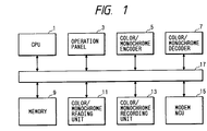
- Fig. 1 is a block diagram showing the configuration of a facsimile apparatus constituting a first embodiment of the present invention.
- the facsimile apparatus is composed of a CPU 1 controlling the entire apparatus; an operation panel 3 for various input key operations by the operator; a color/monochromatic encoder 5 for encoding of color/monochromatic image data; a color/monochromatic decoder 7 for decoding of color/monochromatic image data; a memory 9 for accumulation of image data etc.; a color/monochromatic reading unit 11 for reading a color/monochromatic original; a color/monochromatic recording unit 13 for recording a color/monochromatic image; and a modem/NCU 15 for modulation/demodulation of color/monochromatic image data and for network control.
- Fig. 3 is a plan view showing a part of said operation panel 3.
- the operation panel 3 is provided with an LCD 31 for displaying the time in normal state, state of the apparatus and content of the set mode; LED displays 32a - 32d for indicating the selected modes; a start key 33 for instructing the start of a transmitting or copying operation; and a mode switching key 34 for instructing a mode switching.
- Other keys are not illustrated because they are not used in the present embodiment.
- Fig. 2 is a flow chart showing the function of the present embodiment in a transmitting operation
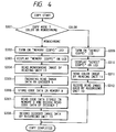
- Fig. 4 is a flow chart showing the function in a copying operation.
- the operator at first designates the transmission mode (color/monochromatic) by the mode switching key 34.
- the transmitting operation is initiated by the actuation of the start key 33, there is at first identified the initially designated transmission mode (S201).
- the "memory" LED 32d is turned on (S202) and a message “memory” is displayed on the LCD 31 (S203) thereby informing the operator of the memory transmission operation.
- the reading unit 11 effects the image reading in the monochromatic mode (S204), and the read data are encoded in the encoder 5 (S205).
- the monochromatic binary data are usually encoded by a method suitable for binary data compression such as MH, MR or JBIG.
- the encoded data are in succession stored in the memory 9 (S206).
- the apparatus After the reading, encoding and memory of all the originals, the apparatus enters an automatic calling operation to connect a line with the destination terminal (S207), and the encoded data, stored in the memory 9, are transmitted to the destination terminal (S208).
- the designated transmission mode is the color mode
- the "direct” LED 32b is turend on (S209) and a message "direct” is displayed on the LCD 31 (S210).
- the automatic calling operation is conducted to connect the line with the address terminal (S211).
- the image reading in the color mode is conducted in the reading unit 11 (S212)
- the read data are encoded in the encoder 5 (S213) and the obtained encoded data are transmitted to the destination terminal (S214).
- the encoding in this case is conducted by a method suitable for compression of a color multi-value image, such as ADCT (adaptive discrete cosine transformation) of JPEG (Joint Photographic Expert Group) or vector quantization.
- the "memory" LED 32d is turned on (S302), and a message “memory” is displayed on the LCD 31 (S303).
- the image reading is conducted in the monochromatic mode in the reading unit 11 (S304), then the read image data are encoded in the encoder 5 (S305), and the obtained encoded data are stored in the memory 9 (S306).
- the image data stored in the memory 9 are read in succession, then decoded in the decoder 7 (S307), and the decoded data are transferred to the recording unit 13 and recorded (S308).
- the storage in the memory 9 is conducted in the unit of a page, the above-explained operations are repeated until all the pages are processed.
- the "direct” LED 32b is turned on (S309) and a message “direct” is displayed on the LCD 31 (S310). Then the image reading is conducted in the color mode in the reading unit (S311), and the read image data are in succession transferred to the recording unit 13 and recorded (S312).
- Fig. 5 is a flow chart showing the memory copy operation in the color and monochromatic modes, in the copying mode.
- the image data stored in the memory 9 are read in succession and decoded in the decoder 7 (S407), and the decoded data are transferred to the recording unit 13 and recorded (S408).
- the storage in the memory 9 is conducted in the unit of a page, the above-explained operations are repeated until all the pages are processed.
- the "memory" LED 32d is turned on (S409), and a message “memory” is displayed on the LCD 31 (S410). Subsequently the image reading is conducted in the color mode in the reading unit 11 (S411), then the read image data are encoded in the encoder 5 (S412), and the encoded data are stored in the memory 9 (S413).
- the image data stored in the memory 9 are read in succession, and decoded in the decoder 7 (S414), and the decoded data are transferred to the recording unit 13 and recorded (S415).
- the storage in the memory 9 is conducted in the unit of a page, the above-explained operations are repeated until all the pages are processed.
- the operations in the copy mode are conducted in the above-explained manner.
- the memory transmission is conducted in the monochromatic mode and the direct transmission is conducted in the color mode, as shown in the flow chart in Fig. 2.
- Fig. 6 is a block diagram showing the configuration of an embodiment of the present invention.
- the image communicating apparatus of the present embodiment is a facsimile apparatus having G3 facsimile functions and adapted to be connected to an analog telephone line, and additionally provided with the functions for transmission and reception of a color image.
- a CPU 1-1 for controlling the entire apparatus
- a ROM 1-2 used as a program memory for storing programs for various controls by the CPU 1-1
- a RAM 1-3 used for example as a work area for the CPU 1-1 and backed up with a battery so as not to lose the content of memory.
- An encode/decode unit 1-4 is provided, as will be detailedly explained later with reference to Figs. 9 and 10, a raster-block conversion unit 4-1, a color converter 4-2, a JPEG encoding unit 4-3 and an MH encoding unit 4-5 as the transmission system, and with a block-raster conversion unit 5-1, a color converter 5-2, a JPEG decoding unit 5-3 and an MH decoding unit 5-5 as the reception system.
- MH encode/decode unit for MH encoding of the entered binary monochromatic signal and for decoding of the MH codes into binary monochromatic signals
- JPEG encode/decode unit and a color conversion circuit for conversion of multi-value color component input signals of red, green and blue of 8 bit/pixel into three signal components of Y, Cr and Cb and generating encoded data by the JPEG baseline endocing, or decoding of JPEG base-line encoded data into Y, Cr, Cb multivalue data of 8 bit/pixel and conversion of said Y, Cr, Cb signal components into C, M, Y, K signals to be used on the printer.
- a modem 1-5 effects modulation and demodulation of the transmission and reception signals, based on the ITU-T recommendation V.17.
- An NCU (network control unit) 1-6 effects connection control with a telephone network.
- a timer unit 1-7 is composed for example of a clock LSI having calendar function.
- An operation panel 1-8 is provided with various operation keys and display units, of which details will be explained later with reference to Fig. 8.
- An image memory 1-9 is composed of a semiconductor memory, so controlled as to store the image data in the unit of a page.
- a color scanner 1-10 optically reads an original with separation into R, G and B components, and releases each color in each pixel as multi-value data of 8 bits.
- a color contact sensor is employed as the reading device, and an automatic document feeder is provided for automatic feeding of the originals to be read.
- a printer interface 1-11 is provided, as shown in Fig. 10, with a binarizing unit 5-6 and an interface control unit 5-7, and effects connection control with a printer unit 1-12 by a general interface 1-13 according to the centronics specification. It controls the general interface 1-13 in such a manner that multi-value input signals of C, M, Y and K colors are transmitted to the printer unit after conversion of each color data into binary data and that monochromatic binary input data are transmitted directly to the printer unit. It also has the function of detecting the status of the printer unit through this interface 1-11 and informing the CPU 1-1 of said status.
- the printer unit 1-12 is capable of color recording and monochromatic recording by the ink jet recording system. There is further provided a CPU bus 1-14 in the present communication.
- Fig. 7 is an external perspective view of the present communication apparatus
- Fig. 8 is a plan view of the operation panel 1-8 mentioned above.
- an original table 2-1 for setting the originals is provided on an upper face of the casing of the apparatus, and the operation panel 1-8 is provided thereon.
- An original discharge tray 2-3 is provided behind said operation panel.
- a recording sheet discharge unit 2-4 Also on the front face of the casing of the apparatus there is provided a recording sheet discharge unit 2-4, and a first recording sheet cassette 2-5 and a second recording sheet cassette 2-6 for storing the recording sheets are provided thereunder.
- the first cassette 2-5 can contain sheets suitable for color recording
- the cassette 2-6 can contain sheets suitable for monochromatic recording.
- numeral keys 3-1 are composed of twelve keys of 0 - 9, # and * and are principally used for entering telephone numbers.
- An LCD unit 3-2 provides displays indicating the status of the apparatus or for confirming the entered telephone number.
- One-touch keys 3-3 are used for one-touch transmission by reading address numbers stored in advance in the RAM 1-3.
- a start key 3-4 is used for instructing, for example, the start of transmission, and a stop key 3-5 is used for interrupting the operation in progress.
- a color key 3-6 for instructing the process as a color original, is provided with lamps respectively in the outer frame portion and in the internal portion of said key.
- the internal lamp in the color key 3-6 is indicated by 3-7.
- a color indicator lamp 3-8 is turned on when a state, capable of color recording, in the printer unit 1-12 is detected.
- a resolution selecting key 3-9 is used for switching the resolution of original image reading, and the state varies upon each depression as shown in Fig. 25.
- the resolution of the image transmitted can be regulated by said key 3-9, either in monochromatic image reading or in color image reading.
- the resolution in the monochromatic mode is made selectable as 8 pel x 15.4 line/mm in the super fine mode, 8 pel x 7.7 line/mm in the fine mode or 8 pel x 3.85 line/mm in the normal mode, while that in the full color mode is fixed at 8 pel x 7.7 line/mm but the content of the dot quantizing table (DQT), used in the JPEG baseline encoding, is changed in the super fine, fine and normal modes.
- DQT dot quantizing table
- Fig. 9 is a block diagram showing the data flow of a transmitted image in the present embodiment
- Fig. 10 is a block diagram showing the data flow in a received image.
- an original 4-7 is illuminated by a white light source 4-8 and is read by the scanner unit 1-10 including a color contact sensor 4-9, and each analog signal, separated into R, G and B primary colors, is converted into 8-bit digital data which are released from said scanner unit 1-10 to the CPU bus.
- said data are supplied through the CPU bus to the encode/decode unit 1-4 for raster-block conversion in a buffer memory (raster-block conversion unit 4-1) therein.
- the 8-bit data supplied from the scanner unit 1-10 in the order of raster scanning and in the order of R, G and B are re-arranged as blocks, each consisting of a matrix of 8 x 8 pixels, thereby generating block-sequential data consisting of a R-block, a G-block, a B-block, a R-block, ...
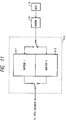
- the communication buffer 4-4 is controlled, as shown in Fig. 11, as double buffers 6-1, 6-2 of a capacity of 64 kByte x 2, composed of a part of the RAM 1-3.
- the JPEG encoded data transmitted by the communication buffer 4-4 are transferred to the modem unit 1-5, and transmitted to the external line from the NCU 1-6.
- the amount of JPEG encoded data per page of the color image is usually in a range of 500 kB to 2 MB, with the resolution of 8 pel x 7.7 line/mm.
- the image memory 1-9 employed in the present embodiment is of a capacity of 256 kB, and cannot, therefore, be used as the page memory for the color image.
- the capacity of 256 kB can sufficiently store the data of a monochromatic page.
- the RGB data released from the color scanner unit 1-10 to the bus are in succession fetched in the RAM 1-3, and the CPU 1-1 samples the G (green) output data only, as the monochromatic signal, which is binary digitized with a predetermined threshold level in a monochromatic binarizing unit 4-6.
- the obtained binary monochromatic data are MH encoded in an MH encoder/decoder 4-5 of the encode/decode unit 1-4 in succession and released to the bus.
- the CPU 1-1 In case of the monochromatic mode, the CPU 1-1 normally stores the MH encoded data in the image memory 1-9, then calls another terminal after the accumulation of the data of at least a page, and effects data transfer from the image memory 1-9 to the communication buffer 4-4 after the line connection. Thus this is a transmission from the memory.
- Fig. 10 for explaining the data flow of the image data in the reception.
- the image data received from the external line through the NCU 1-6 and the modem 1-5 are supplied to the communication buffer 4-4, and, in case of a color image, the image data are transferred therefrom to the encode/decode unit 1-4.
- the encode/decode unit 1-4 decodes the received data by JPEG baseline decoding to obtain block-sequential YCrCb data, which are then converted in the color conversion unit into block sequential data of CMY (cyan/magenta/yellow) color space.
- Said block-sequential CMY data are then subjected to block-raster conversion to sequential raster data train of C, M and Y colors, which are supplied to the printer interface unit 1-11.
- Said printer interface 1-11 effects CMYK color separation by black component extraction through the processing of the input data train, and binary digitizes each data for supply to the printer unit 1-12.
- the image memory 1-9 is not used as the color image page memory also in the reception.
- the data of monochromatic images are received by the communication buffer 4-4, said data are usually accumulated in succession, in the unit of a page, in the image memory 1-9, and are read, after the accumulation of at least a monochromatic page, by the encode/decode unit 1-4 for MH decoding.
- the decoded monochromatic binary image data are then supplied to the printer interface unit 1-11, which effects control without passing of the binarizing unit 5-6.
- Fig. 11 is a block diagram showing the control system of the communication buffer 4-4.
- the communication buffer 4-4 is composed of a buffer 6-1 of 64 kByte and a buffer 6-2 of 64 kByte, corresponding to the partial page size in the ECM (error correction mode) communication defined in the ITU-T recommendation T.30.
- image data of 64 kBytes are received for example by the buffer 6-1, they are checked for data errors, and, in the absence of data errors, the received data are transferred from the buffer 6-1 to the encode/decode unit (or image memory), and, during said transfer, the next partial page is received by the buffer 6-2.
- the reception of the buffer 6-2 is completed during the transfer of the data from the buffer 6-1, an RNR signal is returned to the other terminal to suspend the start of transmission of the next partial page (cf. Fig. 16).
- Fig. 12 is a block diagram showing the configuration of the printer unit 1-12.
- the printer unit 1-12 is provided with a printer control unit 7-1 for controlling said printer unit 1-12, a cartridge control switch 7-2 for switching the cartridges according to a cartridge switching signal 7-3 from said printer control unit 7-1, a motor A 7-4 for moving a cartridge A 7-5 along the main scanning direction of the recording sheet, and a motor B 7-6 for similarly moving a cartridge B 7-7.
- the printer control unit 7-1 is connected to the cartridge A 7-5, thereby activating said cartridge or detecting the status thereof.
- the cartridge B 7-7 can be similarly controlled.
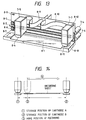
- Fig. 13 is an external perspective view of the cartridges A, B and a driving mechanism for the recording sheet.
- a common guide shaft 8-2 for moving both cartridges 7-5, 7-7; a drive belt 8-5 for driving the cartridge A along the guide shaft 8-2; a similar drive belt 8-6 for the cartridge B; a retraction area 8-7 for retracted storage of the cartridge A; a retraction sensor 8-8 for detecting that the cartridge A is set in the retracted position; a retraction sensor 8-12 for the cartridge B; a retraction area 8-13 for the cartridge B; a stepping motor A 8-14 for driving the drive belt 8-5 for the cartridge A; and a stepping motor B 8-15 for driving the drive belt 8-6 for the cartridge B.
- the cartridge A 7-5 and the cartridge B 7-7 composed of plastic packages of a same shape, are respectively provided with ink discharge heads 8-4, 8-11, and are connected to flexible cables 8-9, 8-10.
- the cartridge attachable to said drive belt and said flexible cable is available in two types; one being the monochromatic cartridge in which the ink tank contains black ink only and the nozzles of the discharge head are all designed for the black ink; and the other being the color cartridge which is same in the external shape as said monochromatic cartridge but in which the ink tank and the nozzles of the discharge head are divided for cyan, magenta, yellow and black inks.
- Such two cartridges same in shape but respectively designed for monochromatic and color functions, are already known in the field of ink jet printers, and the construction of the recording unit in the present embodiment, utilizing plurality of such existing cartridges, is advantageous for the manufacturing cost of the apparatus.
- Each of the above-mentioned two cartridges is capable of supplying an electrical identification signal to the flexible cable, so that the printer control unit 7-1 can identify, by switching the switching signal 7-3 in succession, whether each of the cartridges A, B shown in Fig. 13 is a monochromatic or color cartridge.
- the cartridges A, B are stored in the respective retraction positions.
- the stepping motor A is rotated by a predetermined number of pulses to move said cartridge A from the storage position (1) to a home position (3) for recording.
- the motor A is driven within a range (4), taking said home position as reference, for effecting recording operation in the main scanning direction of the recording sheet, which is advanced in combination.
- the cartridge A is once returned to the position (3) and is then stored in the position (1).
- the cartridge B is moved from the retraction position (2) to the home position (3), and effects recording in the range (4).
- a table in Fig. 38 indicates the algorithm of lighting of the color indicator 3-8, depending on the status of the printer.
- a DIS signal shown in Fig. 19 sets full color expansion area of 1 byte, for the DIS signal defined by the ITU-T recommendation T.30.
- a bit 7 "different encodings in document” set at "1" and a bit 1 "JPEG color function” set at "1" in the expansion area indicate that the receiving side is capable of receiving a document containing a JPEG encoded full color page and an at least MH-encoded monochromatic page.
- said bit 7 set at "0" indicates that the receiving side is incapable of receiving, within a single communication, an image page encoded by other than JPEG method.
- a DCS signal shown in Fig. 20 sets a full color expansion area of 1 byte, for the DCS signal defined by the ITU-T recommendation T.30.
- Fig. 15 illustrates an example of the protocol of an ordinary monochromatic communication
- Fig. 16 illustrates an example of the protocol of a color communication.
- Fig. 15 shows a case in which all the transmitted images are once accumulated in the image memory prior to the MH encoding.
- the protocols shown in Fig. 15 are already well known in the G3 facsimile and will not, therefore, be explained in detail.
- the receiving unit can detect that (1) the initial page is monochromatic, but (2) a JPEG color page may be transmitted afterwards.
- Fig. 16 shows a case in which all the pages contain color images, and the bit 1 of the color expansion area of the initial DCS is set at "1" (to be used).
- the receiving unit cannot use the image memory 1-9, and the data received by the communication buffer 4-4 are suitably transferred to the JPEG decoding circuit 5-3.
- the RNR signal is returned to temporarily suspend the transmission.
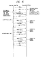
- Figs. 17 and 18 show examples of communication sequence containing monochromatic pages and color pages in mixed manner.
- Fig. 17 shows an example of the sequence in which the receiving unit detects the presence of the color expansion area in the initial DCS, thereby printing all the received pages directly without using the image memory 1-9.
- Fig. 18 shows an example of the sequence in which the receiving unit stores all the monochromatic pages in the image memory 1-9 and printing thus stored monochromatic pages after the reception and recording of all the color pages are completed.
- the color expansion area is added to the initial DCS, but the bit 1 thereof is set at "0", and a mode change is indicated by PPS-EOM immediately before the transmission of a color page.
- the receiving side again declares the presence of color receiving capability, and the transmitting side sets the bit 1 of the color expansion area at "1" in the next DCS.
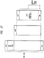
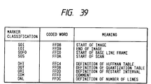
- Fig. 21 schematically shows the data structure of the JPEG baseline encoded data defined by the ITU-T recommendation.
- Data of a page are composed of an image frame, sandwiched between SOI and EOI markers.
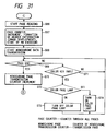
- the image frame contains various parameters associated with the marker code as shown in Fig. 39, and a baseline frame starting with SOF0.
- Said baseline frame contains a scan frame starting with a SOS marker, and said scan frame contains JPEG-encoded compressed image data.
- Fig. 22 is a schematic view showing the content of the page header information for the comment (COM) marker parameters in the present embodiment.
- page header information containing for example the ID information of the transmitting unit, calendar information, page number etc.
- page header information is usually formed as an image in the transmitting unit and is transmitted by addition to the image of a transmitted page. In this manner said page header information can be conveniently reproduced in the received image.
- the header information is formed as an image as in the case of monochromatic facsimile, attached to the transmitted image and JPEG encoded
- page header information may be deteriorated in quality and become illegible at the receiving side, because the JPEG baseline encoding is an irreversible encoding not ensuring faithful reproduction of the original image, and because the deterioration in image quality is significant for characters.
- character information as shown in Fig. 22 is prepared as the parameters of the COM marker in the JPEG data and transmitted to the receiving unit.
- (A) stands for the abbreviated name of the transmitting unit; (B) is the calendar information read from the clock unit; and (C) indicates the page number.
- the receiving unit having received a color page, prints the character information of the COM marker on the recording sheet at the recording of the received image, thereby providing header information easily recognizable by the user, as in the page header of the received monochromatic page.
- Fig. 23 is a flow chart showing the operation sequence of the transmitting operation. The details of said sequence, in case of color transmission, are shown in Figs. 26 and 28 to 31, and, in case of ordinary monochromatic transmission, in Figs. 26 and 27.
- an address telephone number is entered by the numeral keys 3-1 (S1) and registered in the RAM 1-3 (S2), and the transmitting operation is subsequently initiated by the depression of the start key 3-4 (S7).
- the transmission is similarly started by the depression of one of the one-touch keys 3-3 (S8).
- the original is at first read and accumulated in the image memory 1-9 (S11). If a next page is not present (S12), the calling operation is made with the dialling number stored in the RAM 1-3 (S13) to effect line connection, and CNG transmission is executed (S14). Upon DIS reception (S15), there is effected DCS transmission without the color expansion area, as explained above (S16). Then, after TCF transmission (S17) and upon CFR reception (S18), there is initiated the transmission of the monochromatic image (S19).
- the line connection is made by a calling operation with the dialling number stored in the RAM 1-3 (S21), and CNG transmission is conducted (S22).
- CNG transmission is conducted (S22).
- DIS reception S23
- there is discirminated the color receiving ability of the receiving unit S24. If the color receiving ability is not available, DCN transmission is made (S23) and the sequence is terminated by an error state.
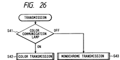
- step S9 there is checked the status of a color communication lamp, to be explained later, (S41) as shown in Fig. 26, and, if said lamp is turned on, the sequence proceeds to a color transmitting operation (S42), but, if said lamp is turned off, the sequence proceeds to a monochromatic transmitting operation (S43).
- the one-touch keys 3-3 are respectively associated, in the RAM, with data tables, in which registered in advance are destination telephone numbers and parameters required for the transmission. Prior to the start of transmission, the operator can select the color mode (S3, S4) and the resolution (S5, S6).
- the color communication lamp at the outside of the color key 3-6 and the color page lamp 3-7 at the inside vary their states in response to depressions of the color key, as shown in Fig. 24.
- a state A in Fig. 24 indicates the aforementioned setting for the monochromatic transmission, while states B, C and D indicate the setting states for color transmission.
- the states B and D are set in case color transmission is conducted in a certain page within a communication, but the first page is monochromatic. Also the state C is set in case color transmission is conducted within a communication and the first page is also a color page.
- the state of the lamps varies between the states B and C (or between C and D) in response to the depressions of the color key 3-6, in order to enable selection, for each page, whether the next page is to be transmitted in the color mode or in the monochromatic mode.
- Fig. 25 shows the state changes in the resolution lamps (super fine and fine) in response to the depressions of the resolution key in the step S5 shown in Fig. 23.
- the image reading resolution varies depending on the super fine mode, fine mode or normal mode (in which both lamps are turned off), but, for the color page, the resolution remains constant but the content of the quantizing table for JPEG encoding is varied.
- plural quantizing tables are registered in advance in the ROM 1-2 and are suitably selected at the JPEG encoding, and the content of the selected quantizing table is transmitted, as shown in Figs. 21 and 22, as a parameter of the DQT marker to the partner terminal.
- the state of the color page lamp is checked at first (S51), and, if it is turned on, the page reading operation is started (S52) and the count of a through page counter is increased by one (S53). Then the color data transmission is started (S54), and the color page lamp is made to intermittently flash (S55).
- the count of a color page transmission counter for counting the number of transmitted color pages, is increased by one (S57). Then the state of the color page lamp is checked (S58), and, if it is intermittently flashing, it is turned on continuously (S59), but, if it is turned off, the page transmission is terminated (S60). Then the sequence returns after the discharge of the original of said page (S61).
- step S51 if the step S51 identifies that the color page lamp is turned off, there is started the page reading operation (S66), and, after the increment of the through page counter, preparation of the header information (image development) and start of MH encoding (S67), there is initiated the transmission of the monochromatic data (S68).
- step S69 identifies the page end
- the count of a monochromatic page transmission counter, for counting the number of transmitted monochromatic pages is increased by one (S70) and the sequence proceeds to the step S60.
- Fig. 37 is a plan view showing the transition of the display of the page counter in the above-explained transmitting operation. As shown in Fig. 37, there are displayed the numbers of entire pages, monochromatic pages and color pages, and the color communication lamp at the outside of the color key 3-6 is turned on at the color transmission while the color page lamp 3-7 at the inside is turned on at the transmission of a color page.
- the line Upon detection of the incoming call, the line is connected (S83), and a response signal DIS to the partner terminal is transmitted.
- the color indicator 3-8 is turned on by the logic shown in Fig. 38 if the printer 1-12 is capable of color recording (S84).
- the color expansion area of 1 byte shown in Fig. 19 is attached to DIS in the transmission (S85, S86), but, in case said color indicator is turned off, said expansion area is not attached to the DIS (S92, S93).
- the color page reception is conducted for the first page, but, if the color reception is not instructed even in case of a DCS containing the expansion area, the monochromatic page reception is conducted for the first page.
- Fig. 34 is a flow chart showing the receiving sequence for each page in the color communication.
- step S111 instructs monochromatic page reception
- the monochromatic mode is instructed to the printer 1-12 (S120)
- the encode/decode unit 1-4 is set at the MH decoding route (S121)
- the decoding operation is started for monochromatic recording (S122).
- S123 an increment of the monochromatic page reception counter
- a next page is present after the image reception of each page in the above-explained manner, the sequence proceeds to the flow chart shown in Fig. 28. If a PPS-MPS indicating the absence of the mode change is received (S100), and if the recording sheet is present (S106), an MCF is transmitted (S107) and the sequence returns to the step S91. If the recording sheet is absent (S106), the sequence is terminated for error.
- Fig. 35 is a flow chart showing the cartridge selecting operation of the printer 1-12, to be executed by the control unit 1-1 for color/monochromatic designation to the printer 1-12 in the steps S111, S112 and S120 in Fig. 34.
- step S131 identifies the monochromatic recording, if any of the cartridges is a monochromatic cartridge (S132), said monochromatic cartridge is selected (S136). Otherwise a color cartridge is selected (S135).
- Fig. 36 is a flow chart showing the recording cassette selecting operation.
- the color recording is designated (S141)
- a recording sheet exclusive for color recording or ink jet recording in order not to deteriorate the quality of the recorded image.
- the cassette 1 is preferentially selected in automatic manner in the color recording (S142 - S145).
- the cassette 2 is preferentially selected in automatic manner in case the step S141 designates monochromatic recording (S146 - S149).
- a memory transmitting operation in the monochromatic mode and a direct transmitting operation in the color mode may be conducted, in the copying, a memory copying operation both in the monochromatic and color modes, thereby preventing the memory overflow by the memory transmission in the color mode and also enabling multipage copying in the color mode.
- the through-the-memory or direction transmission/copying operations are executed by the identification of the designated monochromatic/color mode and of the transmission/copying operation, the operator is not required to designate the through-the-memory operation or the direct operation but is only required to select the monochromatic or color mode, so that the operation efficiency can be improved.
Landscapes
- Engineering & Computer Science (AREA)
- Multimedia (AREA)
- Signal Processing (AREA)
- Color Image Communication Systems (AREA)
- Facsimile Transmission Control (AREA)
- Facsimile Image Signal Circuits (AREA)
Applications Claiming Priority (4)
| Application Number | Priority Date | Filing Date | Title |
|---|---|---|---|
| JP34484693A JP3402717B2 (ja) | 1993-12-20 | 1993-12-20 | 画像通信装置および画像通信方法 |
| JP344846/93 | 1993-12-20 | ||
| JP348674/93 | 1993-12-27 | ||
| JP34867493A JP3332537B2 (ja) | 1993-12-27 | 1993-12-27 | 画像通信装置および画像通信方法 |
Publications (3)
| Publication Number | Publication Date |
|---|---|
| EP0660581A2 true EP0660581A2 (de) | 1995-06-28 |
| EP0660581A3 EP0660581A3 (de) | 1996-04-03 |
| EP0660581B1 EP0660581B1 (de) | 1999-05-06 |
Family
ID=26577887
Family Applications (1)
| Application Number | Title | Priority Date | Filing Date |
|---|---|---|---|
| EP94309490A Expired - Lifetime EP0660581B1 (de) | 1993-12-20 | 1994-12-19 | Bildübertragungsgerät |
Country Status (4)
| Country | Link |
|---|---|
| US (1) | US5719686A (de) |
| EP (1) | EP0660581B1 (de) |
| DE (1) | DE69418295T2 (de) |
| ES (1) | ES2131645T3 (de) |
Families Citing this family (22)
| Publication number | Priority date | Publication date | Assignee | Title |
|---|---|---|---|---|
| JPH0955823A (ja) * | 1995-06-08 | 1997-02-25 | Canon Inc | ファクシミリ装置および画像処理方法 |
| US5896207A (en) * | 1995-11-13 | 1999-04-20 | Brother Kogyo Kabushiki Kaisha | Color printer and facsimile apparatus which outputs in color or monochrome based on predetermined conditions |
| JP3607436B2 (ja) * | 1995-12-18 | 2005-01-05 | 株式会社リコー | ファクシミリ装置及びファクシミリ通信システム |
| JP3530295B2 (ja) * | 1995-12-22 | 2004-05-24 | 株式会社リコー | ファクシミリ装置 |
| JPH09214580A (ja) * | 1996-02-06 | 1997-08-15 | Canon Inc | 通信システム |
| JP3420444B2 (ja) * | 1996-10-17 | 2003-06-23 | キヤノン株式会社 | 画像形成装置、画像形成方法、及びその記憶媒体 |
| JP3304858B2 (ja) * | 1997-11-28 | 2002-07-22 | 富士ゼロックス株式会社 | 画像送信装置および画像送信方法 |
| US6961152B1 (en) * | 1998-01-08 | 2005-11-01 | Brother Kogyo Kabushiki Kaisha | Multi-functional device having vertically arranged scanner and printer sections |
| JP3817888B2 (ja) | 1998-02-26 | 2006-09-06 | ブラザー工業株式会社 | コピー装置・読取装置・記録装置 |
| JP3937656B2 (ja) * | 1999-06-30 | 2007-06-27 | キヤノン株式会社 | 画像処理装置及びその制御方法及び記憶媒体 |
| JP2001016474A (ja) | 1999-06-30 | 2001-01-19 | Canon Inc | 画像形成装置及びその制御方法及び記憶媒体 |
| JP2001016462A (ja) * | 1999-06-30 | 2001-01-19 | Canon Inc | 画像通信方法及びその装置 |
| US7119915B2 (en) * | 2000-02-21 | 2006-10-10 | Canon Kabushiki Kaisha | Communication apparatus and method |
| JP2001358950A (ja) * | 2000-06-12 | 2001-12-26 | Canon Inc | 画像読取装置及びその制御方法 |
| JP3970551B2 (ja) * | 2001-05-09 | 2007-09-05 | シャープ株式会社 | 画像送信装置 |
| JP4039008B2 (ja) * | 2001-06-19 | 2008-01-30 | セイコーエプソン株式会社 | 印刷記録材容器の検出 |
| JP2004221633A (ja) * | 2003-01-09 | 2004-08-05 | Ricoh Co Ltd | 画像処理装置、画像処理用プログラム及び記憶媒体 |
| TW200502833A (en) * | 2003-07-14 | 2005-01-16 | Benq Corp | Image processing device having a lock button |
| JP2006020032A (ja) * | 2004-07-01 | 2006-01-19 | Canon Inc | 画像処理装置及び画像処理方法 |
| US8165412B2 (en) * | 2007-02-16 | 2012-04-24 | Samsung Electronics Co., Ltd. | Method for decoding binary image at high speed |
| JP7310221B2 (ja) | 2019-03-28 | 2023-07-19 | ブラザー工業株式会社 | 画像形成装置、画像形成方法および画像形成プログラム |
| JP2024013936A (ja) * | 2022-07-21 | 2024-02-01 | キヤノン株式会社 | 画像形成装置、画像形成装置の制御方法、及びプログラム |
Family Cites Families (10)
| Publication number | Priority date | Publication date | Assignee | Title |
|---|---|---|---|---|
| DE3408321A1 (de) * | 1983-03-08 | 1984-09-13 | Canon K.K., Tokio/Tokyo | Bildverarbeitungssystem |
| JPH0744681B2 (ja) * | 1985-10-08 | 1995-05-15 | キヤノン株式会社 | 画像処理装置 |
| US4926250A (en) * | 1987-04-24 | 1990-05-15 | Canon Kabushiki Kaisha | Color image recording and reproducing apparatus utilizing a monochromatic recording medium |
| JP2915048B2 (ja) * | 1989-04-04 | 1999-07-05 | 株式会社リコー | カラー画像処理装置 |
| JP2783617B2 (ja) * | 1989-10-31 | 1998-08-06 | キヤノン株式会社 | カラー画像処理装置及び方法 |
| DE4034540C2 (de) * | 1989-10-31 | 1999-11-11 | Canon Kk | Verfahren und Gerät zur Bildverarbeitung |
| US5241403A (en) * | 1990-09-28 | 1993-08-31 | Canon Kabushiki Kaisha | Image communication system including means for storing function information of destination receiving machine |
| US5537231A (en) * | 1991-08-30 | 1996-07-16 | Canon Kabushiki Kaisha | Image transmission apparatus |
| JP3264017B2 (ja) * | 1993-02-24 | 2002-03-11 | キヤノン株式会社 | 画像送信装置及び方法 |
| JP3332537B2 (ja) * | 1993-12-27 | 2002-10-07 | キヤノン株式会社 | 画像通信装置および画像通信方法 |
-
1994
- 1994-12-15 US US08/356,643 patent/US5719686A/en not_active Expired - Lifetime
- 1994-12-19 ES ES94309490T patent/ES2131645T3/es not_active Expired - Lifetime
- 1994-12-19 DE DE69418295T patent/DE69418295T2/de not_active Expired - Lifetime
- 1994-12-19 EP EP94309490A patent/EP0660581B1/de not_active Expired - Lifetime
Also Published As
| Publication number | Publication date |
|---|---|
| ES2131645T3 (es) | 1999-08-01 |
| EP0660581A3 (de) | 1996-04-03 |
| EP0660581B1 (de) | 1999-05-06 |
| DE69418295D1 (de) | 1999-06-10 |
| DE69418295T2 (de) | 1999-10-14 |
| US5719686A (en) | 1998-02-17 |
Similar Documents
| Publication | Publication Date | Title |
|---|---|---|
| US5719686A (en) | Image communicating apparatus | |
| US5956162A (en) | Data communicating apparatus for selectively recording color and monochromatic images on different recording members | |
| EP0660582B1 (de) | Bildübertragungsgerät und -verfahren | |
| US5751449A (en) | Image communicating apparatus | |
| US6323962B1 (en) | Facsimile machine with facsimile data receiver and external computer | |
| US7092113B1 (en) | Image communication apparatus, method and storage medium for transmitting or receiving a color image | |
| US6278529B1 (en) | Color communication apparatus and method thereof and storage medium for storing said method | |
| JPH0595490A (ja) | フアクシミリ装置 | |
| EP0530034B1 (de) | Gerät zur Bildübertragung | |
| US5838822A (en) | Image communicating apparatus | |
| JP2004096688A (ja) | 画像形成装置、印字制御方法、プログラム、及び記憶媒体 | |
| JP3332537B2 (ja) | 画像通信装置および画像通信方法 | |
| US5684604A (en) | Image transmission method and apparatus therefor | |
| US6970262B1 (en) | Color image communication apparatus | |
| JP3332538B2 (ja) | 画像通信装置および画像通信方法 | |
| JP3387600B2 (ja) | 画像受信装置および画像受信方法 | |
| JP3406932B2 (ja) | 画像通信装置および画像通信方法 | |
| JP3402717B2 (ja) | 画像通信装置および画像通信方法 | |
| JP3372626B2 (ja) | 画像通信装置および画像通信方法 | |
| US20040070780A1 (en) | Color image communication device | |
| JPH07203164A (ja) | 画像通信装置 | |
| JPH07203225A (ja) | 画像通信装置 | |
| JPH07203222A (ja) | 画像通信装置 | |
| JPH07177332A (ja) | 画像通信装置 | |
| JPH07203106A (ja) | 画像通信装置 |
Legal Events
| Date | Code | Title | Description |
|---|---|---|---|
| PUAI | Public reference made under article 153(3) epc to a published international application that has entered the european phase |
Free format text: ORIGINAL CODE: 0009012 |
|
| AK | Designated contracting states |
Kind code of ref document: A2 Designated state(s): DE ES FR GB IT |
|
| PUAL | Search report despatched |
Free format text: ORIGINAL CODE: 0009013 |
|
| AK | Designated contracting states |
Kind code of ref document: A3 Designated state(s): DE ES FR GB IT |
|
| 17P | Request for examination filed |
Effective date: 19960816 |
|
| 17Q | First examination report despatched |
Effective date: 19970605 |
|
| GRAG | Despatch of communication of intention to grant |
Free format text: ORIGINAL CODE: EPIDOS AGRA |
|
| GRAG | Despatch of communication of intention to grant |
Free format text: ORIGINAL CODE: EPIDOS AGRA |
|
| GRAH | Despatch of communication of intention to grant a patent |
Free format text: ORIGINAL CODE: EPIDOS IGRA |
|
| GRAH | Despatch of communication of intention to grant a patent |
Free format text: ORIGINAL CODE: EPIDOS IGRA |
|
| GRAA | (expected) grant |
Free format text: ORIGINAL CODE: 0009210 |
|
| AK | Designated contracting states |
Kind code of ref document: B1 Designated state(s): DE ES FR GB IT |
|
| REF | Corresponds to: |
Ref document number: 69418295 Country of ref document: DE Date of ref document: 19990610 |
|
| ET | Fr: translation filed | ||
| REG | Reference to a national code |
Ref country code: ES Ref legal event code: FG2A Ref document number: 2131645 Country of ref document: ES Kind code of ref document: T3 |
|
| PLBE | No opposition filed within time limit |
Free format text: ORIGINAL CODE: 0009261 |
|
| STAA | Information on the status of an ep patent application or granted ep patent |
Free format text: STATUS: NO OPPOSITION FILED WITHIN TIME LIMIT |
|
| 26N | No opposition filed | ||
| REG | Reference to a national code |
Ref country code: GB Ref legal event code: IF02 |
|
| PGFP | Annual fee paid to national office [announced via postgrant information from national office to epo] |
Ref country code: ES Payment date: 20041201 Year of fee payment: 11 |
|
| PGFP | Annual fee paid to national office [announced via postgrant information from national office to epo] |
Ref country code: FR Payment date: 20041220 Year of fee payment: 11 |
|
| PG25 | Lapsed in a contracting state [announced via postgrant information from national office to epo] |
Ref country code: IT Free format text: LAPSE BECAUSE OF NON-PAYMENT OF DUE FEES Effective date: 20051219 |
|
| PG25 | Lapsed in a contracting state [announced via postgrant information from national office to epo] |
Ref country code: ES Free format text: LAPSE BECAUSE OF NON-PAYMENT OF DUE FEES Effective date: 20051220 |
|
| PG25 | Lapsed in a contracting state [announced via postgrant information from national office to epo] |
Ref country code: FR Free format text: LAPSE BECAUSE OF NON-PAYMENT OF DUE FEES Effective date: 20060831 |
|
| REG | Reference to a national code |
Ref country code: FR Ref legal event code: ST Effective date: 20060831 |
|
| REG | Reference to a national code |
Ref country code: ES Ref legal event code: FD2A Effective date: 20051220 |
|
| PGFP | Annual fee paid to national office [announced via postgrant information from national office to epo] |
Ref country code: GB Payment date: 20121219 Year of fee payment: 19 |
|
| PGFP | Annual fee paid to national office [announced via postgrant information from national office to epo] |
Ref country code: DE Payment date: 20121231 Year of fee payment: 19 |
|
| REG | Reference to a national code |
Ref country code: DE Ref legal event code: R119 Ref document number: 69418295 Country of ref document: DE |
|
| GBPC | Gb: european patent ceased through non-payment of renewal fee |
Effective date: 20131219 |
|
| REG | Reference to a national code |
Ref country code: DE Ref legal event code: R119 Ref document number: 69418295 Country of ref document: DE Effective date: 20140701 |
|
| PG25 | Lapsed in a contracting state [announced via postgrant information from national office to epo] |
Ref country code: DE Free format text: LAPSE BECAUSE OF NON-PAYMENT OF DUE FEES Effective date: 20140701 |
|
| PG25 | Lapsed in a contracting state [announced via postgrant information from national office to epo] |
Ref country code: GB Free format text: LAPSE BECAUSE OF NON-PAYMENT OF DUE FEES Effective date: 20131219 |