EP0660599A1 - Verfahren mit einer teildurchsichtigen Abschirmung zum Ausgleich der Röntgenbilddarstellung von Streustrahlen in Röntgenbildern - Google Patents
Verfahren mit einer teildurchsichtigen Abschirmung zum Ausgleich der Röntgenbilddarstellung von Streustrahlen in Röntgenbildern Download PDFInfo
- Publication number
- EP0660599A1 EP0660599A1 EP93203671A EP93203671A EP0660599A1 EP 0660599 A1 EP0660599 A1 EP 0660599A1 EP 93203671 A EP93203671 A EP 93203671A EP 93203671 A EP93203671 A EP 93203671A EP 0660599 A1 EP0660599 A1 EP 0660599A1
- Authority
- EP
- European Patent Office
- Prior art keywords
- image
- scatter
- radiation
- partially transparent
- signal
- Prior art date
- Legal status (The legal status is an assumption and is not a legal conclusion. Google has not performed a legal analysis and makes no representation as to the accuracy of the status listed.)
- Granted
Links
- 230000005855 radiation Effects 0.000 title claims abstract description 175
- 238000000034 method Methods 0.000 title claims abstract description 57
- 238000003384 imaging method Methods 0.000 title description 18
- 239000000463 material Substances 0.000 claims abstract description 101
- 238000001228 spectrum Methods 0.000 claims description 29
- XAGFODPZIPBFFR-UHFFFAOYSA-N aluminium Chemical compound [Al] XAGFODPZIPBFFR-UHFFFAOYSA-N 0.000 claims description 25
- 229910052782 aluminium Inorganic materials 0.000 claims description 25
- OAICVXFJPJFONN-UHFFFAOYSA-N Phosphorus Chemical compound [P] OAICVXFJPJFONN-UHFFFAOYSA-N 0.000 claims description 19
- 230000002238 attenuated effect Effects 0.000 claims description 13
- 239000010949 copper Substances 0.000 claims description 12
- RYGMFSIKBFXOCR-UHFFFAOYSA-N Copper Chemical compound [Cu] RYGMFSIKBFXOCR-UHFFFAOYSA-N 0.000 claims description 11
- 229920005479 Lucite® Polymers 0.000 claims description 11
- 229910052802 copper Inorganic materials 0.000 claims description 11
- 239000004926 polymethyl methacrylate Substances 0.000 claims description 11
- 239000004417 polycarbonate Substances 0.000 claims description 10
- 229920000515 polycarbonate Polymers 0.000 claims description 10
- 230000004936 stimulating effect Effects 0.000 claims description 5
- 210000004872 soft tissue Anatomy 0.000 claims description 3
- 230000000638 stimulation Effects 0.000 claims description 3
- 210000000988 bone and bone Anatomy 0.000 claims description 2
- 241001274197 Scatophagus argus Species 0.000 claims 2
- 238000013016 damping Methods 0.000 claims 1
- 239000012780 transparent material Substances 0.000 claims 1
- 238000004364 calculation method Methods 0.000 abstract description 17
- 230000000694 effects Effects 0.000 abstract description 7
- 230000001678 irradiating effect Effects 0.000 abstract 1
- 238000010521 absorption reaction Methods 0.000 description 9
- 230000001419 dependent effect Effects 0.000 description 4
- 229910052688 Gadolinium Inorganic materials 0.000 description 2
- 231100000987 absorbed dose Toxicity 0.000 description 2
- 230000008901 benefit Effects 0.000 description 2
- 230000008859 change Effects 0.000 description 2
- 210000000038 chest Anatomy 0.000 description 2
- 230000005284 excitation Effects 0.000 description 2
- UIWYJDYFSGRHKR-UHFFFAOYSA-N gadolinium atom Chemical compound [Gd] UIWYJDYFSGRHKR-UHFFFAOYSA-N 0.000 description 2
- 230000004807 localization Effects 0.000 description 2
- 238000005259 measurement Methods 0.000 description 2
- 239000011368 organic material Substances 0.000 description 2
- 230000008569 process Effects 0.000 description 2
- 238000012897 Levenberg–Marquardt algorithm Methods 0.000 description 1
- 241001465754 Metazoa Species 0.000 description 1
- 238000002083 X-ray spectrum Methods 0.000 description 1
- 238000001514 detection method Methods 0.000 description 1
- 238000002059 diagnostic imaging Methods 0.000 description 1
- 238000006073 displacement reaction Methods 0.000 description 1
- 230000009977 dual effect Effects 0.000 description 1
- 238000002594 fluoroscopy Methods 0.000 description 1
- 230000004907 flux Effects 0.000 description 1
- 239000011159 matrix material Substances 0.000 description 1
- 238000005457 optimization Methods 0.000 description 1
- 230000009467 reduction Effects 0.000 description 1
- 238000005070 sampling Methods 0.000 description 1
- 230000011218 segmentation Effects 0.000 description 1
- 239000000126 substance Substances 0.000 description 1
- 238000003325 tomography Methods 0.000 description 1
Images




Classifications
-
- A—HUMAN NECESSITIES
- A61—MEDICAL OR VETERINARY SCIENCE; HYGIENE
- A61B—DIAGNOSIS; SURGERY; IDENTIFICATION
- A61B6/00—Apparatus or devices for radiation diagnosis; Apparatus or devices for radiation diagnosis combined with radiation therapy equipment
- A61B6/58—Testing, adjusting or calibrating thereof
- A61B6/582—Calibration
- A61B6/583—Calibration using calibration phantoms
Definitions
- the present invention relates to a method for compensating x-ray imaging systems for radiation scatter.
- the total flux of detected radiation consists not only of photons that did not interact with the elements of the attenuating object being imaged but also of radiation scatter.
- the amount of radiation scatter can be very large.
- this radiation can be an important source of error and must be compensated in order to have satisfying results.
- the scatter corrected image is obtained by subtracting the scatter-surface from the second image.
- Another implementation of the method with the lead beam stops in which only the x-ray irradiation with the disk sampler is made has the disadvantage that all the information about the object is lost under the beam stops. This can be an important disadvantage.
- the PMD method allows both primary and scatter signals to be acquired simultaneously, it has two main disadvantages; it is unknown how the drop in scatter radiation relates to location, scattering geometry, patient, etc.. Another disadvantage is that it is practically impossible to match the modulator and the demodulators. Therefore the results are based on rough estimates and the accuracy is reduced.
- a second embodiment of the method for generating a scatter-compensated radiation image in accordance with the present invention is in particular advantageous in case of an exposure of an object by means of a irradiation source emitting polychromatic irradiation.
- This method comprises the steps of
- Basis materials are materials that have such characteristics that the attenuation properties of an organic material in the human body can be deduced from the attenuation caused by a combination of such basis materials.
- Primary photons are photons of non-scattered transmitted radiation.
- the radiation image of the combination of said object and said shield is detected by means of an area detector consisting of a photostimulable phosphor screen and wherein said radiation image is read out and converted into an electrical signal representation by scanning said screen by means of stimulating irradiation and by detecting the light emitted upon stimulation and converting the detected light into an electric signal.
- a partially transparent body is generally meant a body of a material that is partially transparent to the irradiation emitted by the source of irradiation (X-ray source for example) so that the partially transparent body when, together with an object being imaged, is exposed to irradiation causes a drop of the primary radiation signal, however the information of the object being imaged is not lost at the position of the body.
- the source of irradiation X-ray source for example
- a partially transparent shield' refers to a shield comprising a plurality of partially transparent bodies of known materials and known thicknesses (as seen by an x-ray going straight from the source through said partially transparent body to the detector).
- the area of a partially transparent body is to be small enough so that the amount of scattered radiation under and in the immediate neighbourhood of said partially transparent body can be assumed to be the same.
- the output device usde for generating a scatter-compensated image can be a hard copy device such as a laser printer or a thermal printer; alternatively it can be a soft copy generating device such as a monitor.
- a feature of the invention is the calculation of the scattered radiation in a specific location of the image through the use of a partially transparent body of a known material and of known thickness, placed in an imaging system between the x-ray source and the object being imaged.
- the area of said partially transparent body (or the width of the body if a strip is used) is small enough to assume in the image the same amount of scattered radiation under and in the immediate neighbourhood of said partially transparent body (in case a strip is used as body : under and in the immediate neighbourhood perpendicular to the strip (the strip is long compared with its width) the amount of scattered radiation is assumed to be the same).
- the radiation intensity signal under the body is extra attenuated in comparison with the signal besides said body.
- the extra attenuation factor is known since the thickness of the partially transparent body, the type of material of said body and the photon energy of the source is known.
- the radiation scatter component of the image of the object in the location of said body is then found by subtracting a signal Q from both signals detected under - and around said body. If the signal, after subtraction of Q, under the partially transparent body, divided by the signal, after subtraction of Q, around said body is equal to said extra attenuation factor, then the signal Q is the real radiation scatter component of the image in the location of said body.
- the said extra attenuation factor can be different in different locations of the image of the object as a consequence of beam hardening.
- the photon energy spectrum is not too broad one can neglect to a certain degree the influence of beam hardening on the extra attenuation factor and estimate said extra attenuation factor in a certain location of the image based on the detected intensity in said location.
- an x-ray imaging system in accordance with the invention which is especially useful for medical applications using conventional x-ray sources (with polychromatic x-radiation), though which is not limited to this application, calibration with two known basis materials is made to be able to calculate accurately the radiation scatter component in the image of the object.
- This calibration means that an image is made of a set of thickness combinations of two basis materials. This image is taken under the same circumstances (which means : same source and source parameters (spectrum), same type of detector) as the image of the object.
- the said body can be decomposed into a combination of two layers of equivalent thicknesses of said basis materials.
- the real radiation scatter signal is the signal for which the calculated body thickness is equal to the real thickness of said body.
- the partially transparent bodies cause an extra drop of the primary radiation signal, the information about the object being imaged is not lost at the positions of the bodies.
- Fig. 1 gives a schematic representation of one x-ray imaging system in which the method according to the invention can be employed.
- Fig. 2 gives a schematic representation of a read-out unit, i.e. a detector signal to electrical signal converter which can be used for the system according to the invention.
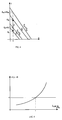
- Fig. 3 gives the representation of the attenuation of the x-ray radiation in function of the thicknesses ⁇ and ⁇ of the basis materials, used in the calibration procedure according to the invention.
- Fig. 4 gives another representation of Fig. 5 and illustrates the calculation, according to the invention, of the thickness of a partially transparent body of the same material as ⁇ .
- Fig. 5 illustrates the typical relationship between the calculated thickness of the partially transparent body and the estimated scattered radiation signal.
- Fig. 6 gives an example of a spectrum of an x-ray source that can be used for an x-ray imaging system in which the method according to the invention can be used.
- Fig. 7 gives an example of the relationship between the thickness of the partially transparent body, the equivalent thickness ⁇ of the basis material and the estimated scatter radiation signal.
- Fig. 8 illustrates the effect of a partially transparent body, made from another material than the basis materials for the calibration.
- Fig. 9 gives the schematic representation of a possible partially transparent shield with which the method according to the invention can be employed.
- Fig. 10 is another schematic representation of another x-ray imaging system in which the method according to the invention can be employed.
- Fig. 11 illustrates the effect of a partially transparent body on the attenuation of the x-ray radiation.
- Fig. 1 refers to the polychromatic case
- Fig. 10 to the monochromatic case. We start with the polychromatic case.
- Fig. 1 gives a schematic representation of an x-ray imaging system and a method for scatter compensation in accordance with the invention.
- the method and system of this embodiment are used in a preferred embodiment for polychromatic x-radiation of the source but can be used also for monochromatic x-radiation.
- an x-ray image of an object is made for which we want to calculate the scattered radiation component and a calibration is made that gives the effect of the beam hardening of the same photon energy spectrum as used for making the object image.
- x-radiation from an x-ray tube 1 (provided with its electronic control circuits which are not shown explicitly) is directed through a partially transparent shield (partially transparent for x-ray radiation) and through an object 3 towards a detector.
- the partially transparent shield consists of a Lucite plate 7 of constant thickness with a plurality of aluminum cylinders 2 placed on it.
- the detector consists of a sheet 5 covered with a layer of x-ray stimulable phosphors in a cassette 6 and of a read-out unit 8.
- plate 7 is used to hold the partially transparent bodies; other manners to keep the bodies in position are possible.
- Essential for using the method according to the invention is that the thickness of a partially transparent body is known.
- a Lucite plate 7 is chosen - other materials which are transparent for x-radiation are possible - because Lucite is a material that is hard enough to keep a constant thickness and to keep a plane shape as well as to attenuate as less as possible the x-ray radiation.
- the partially transparent bodies 2 do not need to have the shape of a cylinder : in one preferred embodiment they have the shape of a cylinder and in another preferred embodiment they have the shape of a strip.
- the material of these partially transparent bodies 2 does not need to be aluminum but in a preferred embodiment aluminum is used as material for these bodies in combination with the use of aluminum and polycarbonate as basis materials in the calibration system 4.
- the screen is held in a cassette 6 which is opaque for light of the visible and the infrared range.
- the stimulable phosphors on the screen 5 have the property to get in a state of excitation after being exposed by x-ray radiation.
- the atoms in excitated state can emit, when they receive a light stimulus of a specific wavelength, light with different wavelengths when they return to their original state.
- the quantity of emitted stimulated light is proportional to the originally absorbed dose of x-ray radiation by the phosphors.
- a read-out unit 8 For reading of the latent image stored in the stimulable phosphor plate a read-out unit 8 is used which is based on opto-electronical reading techniques combined with digital writing in a computer.
- Fig. 1 we call detector the phosphor sheet 5 in the cassette 6 plus the read-out unit 8. Of course other types of detectors can be used.
- FIG. 2 shows a photostimulable phosphor sheet 5 that has been exposed to x-rays.
- the latent image stored in the photostimulable phosphor sheet is read-out by scanning the phosphor sheet with stimulating rays emitted by a laser 9.
- the stimulating rays are reflected according to the main scanning direction by means of a galvanometric deflection device 10.
- the secondary scanning motion of performed by transporting the phosphor sheet in the direction perpendicular to the scanning direction.
- a light collector 11 directs the light obtained by stimulated emission onto a photomultiplier 12 where it is converted into an electrical signal, which is next sampled by a sample and hold circuit 13, and converted, into a digital signal by means of an analogue to digital converter 14.
- the signal is also applied to a square root amplifier so that the output image representing signal also called 'original or raw' image is a signal which is proportional to the square root of applied exposure values and represents the pixel value in a large pixel matrix (for example 2048x2464 pixels).
- the signal which is proportional to the square root of applied exposure values is squared 17 and gives the image of the object, IMAGE A 18, which represents a signal I (x, y) (in function of the pixel coordinates x and y of the image) which is proportional to the absorbed x-ray radiation by the phosphor sheet 5.
- the number of bits used for the values of I can be chosen according to the desired grey value resolution. In the embodiment of Fig. 1 a thorax is chosen as the object to be imaged. Of course other objects are possible.
- a second image is made with exactly the same type of detector and source and source parameters (kV, mAs, focusing) as for IMAGE A 18 and with exactly the same relative position of the source 1 to the stimulable phosphor sheet 5 in the cassette 6.
- the read-out unit and the square unit convert the stored x-ray radiation of the sheet 5 to an image IMAGE B 19 that represents a signal I o (x,y) (in function of the pixel coordinates x and y of the image) which is proportional to the x-ray radiation absorbed by the phosphor sheet 5, with the same proportionality factor as for IMAGE A 18.
- IMAGE B 19 is made just after or before IMAGE A 18, but this is not necessary.
- a calibration is made which allows to calculate accurately the radiation scatter signal in the image IMAGE A 18 of the object at the locations of the partially transparent bodies, which are indicated by 2 in the embodiment of Fig. 1.
- the calibration is especially useful for but not limited to medical applications.
- IMAGE C 20 In the same embodiment of Fig. 1 a third image is made for this purpose, IMAGE C 20. As said before this calibration must allow to calculate accurately the radiation scatter signal in the IMAGE A 18 in the locations of the partially transparent bodies.
- the image is made in the same way as given above for IMAGE A 18 and IMAGE B 19, but in this case the object being imaged is a combination of thicknesses 4 of two different materials which have a different x-ray absorption behaviour. These two materials belong to the group of materials that interact by approximately two physical processes with x-ray photons of energies of the range of most x-ray tubes : through Compton scatering and through photoelectrical absorption.
- two materials of this group can be chosen as basis materials which means here that the x-ray attenuation coefficients of all the other materials of the group can be found by a linear combination of those of the two basis materials.
- the two basis materials are often chosen to be a soft tissue equivalent material respectively a bone equivalent material.
- Other materials can be chosen as basis materials.
- a radiographic phantom suitable for generating the required calibration data generally comprises
- this calibration phantom comprises 36 cylindrical containers, that are filled with a number of combinations of thicknesses of basic materials.
- the basic materials are aluminum and polycarbonate.
- the frame for holding the containers and directing them towards the radiation source consists of two parallel positioned plates.
- a first so-called baseplate has a number of recesses into which the cylindrical containers fit.
- the baseplate is preferably a metallic plate provided with a lead layer in between the recesses so that x-rays cannot penetrate throught the plate at locations in between the containers and hence cannot expose the detector to scatter.
- a second plate referred to as supporting plate.
- the supporting plate has a number of holes through which the cylindrical containers are directed. The position of the holes in the support plate together with the position of the support plate relative to the base plate provide that the cylindrical containers are all directed towards a source of irradiation.
- cylindrical containers were directed towards a single point located at a known distance, in this example 150 cm, measured above the center of the baseplate.
- the supporting plate can be held above the baseplate by means of a fixed connection.
- the support plate is movable.
- a movable support plate is preferred in case calibration data are to be obtained for different positions of the radiation source, i.e. for a set of distances between a source of irradiation and a detector.
- a movable support plate provides that the direction into which the cylindrical containers point, can be changed hereby enabling that the containers are directed towards a source of irradiation positioned at a several distinct distances within a given range of distances.
- the support plate can be fixed for a certain distance of the irradiation source relative to the frame and can be changed for other distances within the given range.
- the distance between the base plate and the support plate is likewise to be doubled in order to have the cylindrical containers point at the irradiation source.
- the change of the angle between the base plate and the axis of the cylindrical containers that are farest away from the center of the base plate which occurs due to the displacement of the support plate, is relatively small.
- the change of the diameter of the openings in the support plate which is required when changing the distance between base plate and support plate is consequently also relatively small and can be bridged by a non-rigid fixing of the containers in the base plate.
- This non rigid fixing can for example be realised by means of an elastically deformable substance positioned in the recessed in the base plate inbetween the cylinders and the base plate.
- the inner wall of the containers is preferably provided with a lead layer so that scattered radiation cannot penetrate through the walls inside the containers.
- a lead beam stop is provided, said beam stop only covering part of the upper surface of the upper material. This lead beam stop provides a measurement of the scattered radiation under the beam stop.
- a cylindrical lead beam stop is provided in the center of the surface of the upper basic material in each cylindrical container.
- the scattered radiation in the shadow of the lead beam stop is measured and subtracted from the signal detected in the neighborhood of the lead beam stop.
- the diameter of all of the cilindrical containers is identical.
- the basic materials are preferably provided in a cylindrical form having a diameter that is slightly smaller than the diameter of the container so that the material fits very well inside the container.
- the calibration image IMAGE C 20 is combined with IMAGE B 19 to generate the calibration data 25.
- the negative logarithm of this ratio is represented in 25 by T(S( ⁇ ), ⁇ , ⁇ ), where S( ⁇ ) is the spectrum of the source (representing the relative distribution of the photon energies) in function of the photon energy ⁇ , ⁇ and ⁇ being the thicknesses of the two basis materials.
- the calibration data are fit to an analytical function F( ⁇ , ⁇ ) ⁇ T( ⁇ , ⁇ ) of the thicknesses of the basismaterials.
- F( ⁇ , ⁇ ) an analytical function proposed in Cardinal HN, Gibson A. Analytical approximation of the log-signal and log-variance functions of x-ray imaging systems, with application to dual-energy imaging, Med. Phys. 18(5), Sept/Oct.
- the calibration can be done independent from the object imaging, but the same spectrum of the photon energy as for the object must be used and the same type of detector.
- the same spectrum of the photon energy as for the object must be used and the same type of detector.
- the object in a certain position (x,y) of IMAGE A 18, can be represented by a combination of thickness aluminum ( ⁇ ) and thickness polycarbonate ( ⁇ ) (as mentioned before). This combination gives the same attenuation (if no scattered radiation is being considered) as the object in said position (x,y), independent from the source and from the detector.
- Another schematic representation of the intensities under and besides the disk is given in Fig. 11. In that figure the disk 2 and the object 3 are shown (the Lucite plate is not shown explicitly because it can be seen as a part of the object) with under it the intensities I z and I m and the scatter radiation component I s .
- the scattered radiation component is a very low frequency component compared with the primary radiation component.
- T represents the attenuation in function of the thicknesses ⁇ and ⁇ of the basis materials for the used source spectrum S( ⁇ ) and detector with absorption coefficient abs( ⁇ ).
- basis material thicknesses ( ⁇ , ⁇ z ) and ( ⁇ , ⁇ m ) the corresponding attenuation values T z and T m are shown, as well as the thickness d of the partially transparent aluminum body.
- the calculation 24 of the scattered radiation component I s of the signal in IMAGE A 18 in the position of the partially transparent body is based on the following idea, which is essential for the method according to the invention.
- the calibration data allow us the calculate the thickness d_c of the partially transparent body in function of the values I zd_est and I md_est .
- Fig. 4 illustrates the calculation.
- (d_c - d) is a monotone increasing function of the estimation I s_est (or of the error ⁇ I s ).
- I s_est or of the error ⁇ I s .
- ⁇ of a polycarbonate we calculate the attenuation (T z + ⁇ T z ) and (T m + ⁇ T m ) in function of the estimated scattered radiation component I s_est .
- the difference in aluminum thickness (Fig. 4) ⁇ m + ⁇ m - ( ⁇ z + ⁇ z ) equals the calculated thickness d_c of the aluminum disk. It can be easily proved that this thickness d_c minus the real thickness d is a monotone increasing function of the estimated scattered radiation component I s_est .
- a shift ⁇ T corresponds to a shift ⁇ .
- ⁇ T For small values of ⁇ T one has : This is valid for the signal under and beside the disk.
- the calibration data are fit to an analytical function T( ⁇ , ⁇ ) (as mentioned before) so that the derivatives of T can be calculated analytically. Although this is not a strict demand, this leads to a higher accuracy.
- the calculation of the scattered radiation component I s is done as follows. If we calculate (d_c - d) for the correct value of ⁇ and for different estimates of I s_est , the zero crossing of the function (d_c - d) versus I s-est gives the value of I s .
- the next step is to search the intervals [i z * ⁇ , (i z +1) * ⁇ ] and [i m * ⁇ , (i m +1) * ⁇ ] for which : F( ⁇ ,i z * ⁇ ) ⁇ F z + ⁇ F z ⁇ F( ⁇ ,(i z + 1)* ⁇ ) F( ⁇ ,i m * ⁇ ) ⁇ F m + ⁇ F m ⁇ F( ⁇ ,(i m + 1)* ⁇ )
- the values of ⁇ z_est and of ⁇ m_est are calculated by linear interpolation.
- the value of ( ⁇ m_est - ⁇ z_est ) is equal to (d_c-d) for I s-est and for ⁇ .
- (d_c-d) For different values of I s_est , covering the scope of expected possible scatter fractions, (d_c-d) is calculated in the same way. It has been shown before that the function (d_c-d) is a monotone increasing function of I s_est . So, with the said values of I s_est , for which (d_c-d) is calculated, and with the values of (d_c-d), a curve is fitted by a linear interpolation technique and the zero crossing gives the value of the scattered radiation component I s .
- Fig. 7 shows a possible spectrum of a conventional x-ray source, used at 140 kV and filtered with 0,3 g/cm2 Gadolinium and 1 mm Cu.
- S( ⁇ ) is the source spectrum filtered by the gadolinium and copper and abs( ⁇ ) is the absorption coefficient of the detector (in this example being a photostimulable phosphor sheet) in function of the photon energy ⁇ .
- Fig. 6 shows the relation between the calculated thickness d_c of an aluminum disk minus the real thickness d versus the estimated scattered radiation signal I s_est .
- the spectrum of Fig. 7 was used for irradiation of 5 mm aluminum and 6 cm polycarbonate.
- the percentile error ⁇ on I s caused by the wrong value of ⁇ in this particular case is very small.
- the aluminum disks (more generally speaking the partially transparent bodies) are localised 22.
- This localisation can be done in different ways.
- the shape of the partially transparent bodies is known and segmentation of the areas in the 'shadow' of these said bodies is not very difficult.
- the scattered radiation component is calculated.
- an interpolation 26 of the values of the scattered component in these positions generates a scattered radiation surface I s (x,y) that represents the scattered radiation component in all positions of the image. Subtracting this scattered radiation surface 26 from the IMAGE A 18 gives IMAGE D 27, the image of the object, compensated for scattered radiation.
- the information about the object under a partially transparent body is not lost; the x-ray radiation signal is just extra attenuated by the body. The effect of the extra attenuation can be eliminated in a further step.
- FIG. 9 Another good realisation of a partially transparent shield is shown in Fig. 9.
- the partially transparent bodies 16 in this embodiment are straight strips positioned parallel on a Lucite plate 7.
- One advantage of this embodiment is that the localisation in the image of the positions of the strips is more easy. We need enough I s data, covering the area of the detector, for an interpolation which gives an accurate estimate of the scattered radiation in the whole image.
- I s data When a strip is used as partially transparent body it is easy to find enough I s data : we can choose easily positions on the strips for which we want to calculate the scattered radiation component in the image, neglecting the positions wherein the x-ray radiation signal varies too much because of sharp edges or other reasons.
- the accuracy of the method increases of course when the partially transparent bodies are directed as good as possible towards the source, perpendicular to the x-ray radiation falling on it, and when the bodies have everywhere the same thickness for this radiation (no smooth edges but sharp ones).
- the height of the disks or strips have at least a height of 4 mm, in order to have enough contrast between the signal under the bodies and the signal beside the bodies.
- the diameters of the bodies must not be too large. Otherwise the scattered radiation signal under the bodies is not equal to the scattered radiation signal beside the bodies. On the other hand the diameters must not be too small because noise and other artifacts have a great influence too on the measured signal under the bodies. It would be good that there are enough pixels under the bodies, so that a local mean value can be used for the signal under a body.
- the factor connecting z and m represents the equivalent thicknesses of the basis materials for the partially transparent shield.
- ⁇ and ⁇ are the thicknesses of the basis materials; the partially transparent body is made from another material then the basis materials and has thickness d. So the primary radiation signal T m detected besides said body in the way which is represented in the graph.
- another material than the basis materials is used for the partially transparent bodies, one has to estimate the two equivalent thicknesses basis material of the object at the position of the partially transparent body, before one can start the calculation of the scattered radiation component. Therefore, for reasons of accuracy, in a preferred embodiment a narrow photon energy spectrum is used for the imaging and a material of the partially transparent bodies is chosen which has a relatively small equivalent thickness of one basis material and a relatively large equivalent thickness of the other basis material.
- Fig. 10 gives another schematic representation of an x-ray imaging system and a method for scatter compensation in accordance with the invention.
- the method and system of this embodiment are used in an embodiment wherein monochromatic x-ray radiation is applied.
- This method can also be applied in case of polychromatic x-radiation with a narrow spectrum of the photon energies. In this case no calibration is made, the beam hardening for monochromatic x-ray radiation is zero and is small for very narrow x-ray spectra.
- X-ray radiation source 1 is directed through a partially transparent shield (partially transparent for x-ray radiation), in a preferred embodiment consisting of a Lucite plate 7 of constant thickness with a plurality of copper cylinders 2 placed on it, and through an object 3 towards a detector, in this preferred embodiment consisting of a sheet 5 covered with a layer of x-ray stimulable phosphors in a cassette 6 and of a read-out unit 8.
- plate 7 is used to hold the partially transparent bodies; other manners to keep the bodies in position are possible.
- Essential for using the method according to the invention is that the thickness of a partially transparent body is known.
- a Lucite plate 7 is chosen - other materials which are transparent for x-ray radiation are possible - because Lucite is a material that is hard enough to keep a constant thickness and to keep a plane shape as well as to attenuate as less as possible the x-ray radiation.
- the partially transparent bodies 2 do not need to have the shape of a cylinder : in a preferred embodiment they have the shape of a cylinder and in another preferred embodiment they have the shape of a strip.
- the material of these partially transparent bodies 2 does not need to be copper but in a preferred embodiment copper is used as material for these bodies because the attenuation of x-ray radiation by copper is rather high so that the height of the copper disks can be limited, which has practical advantages.
- the sheet 5 is held in a cassette 6 which is opaque for light of the visible and the infrared range.
- the stimulable phosphors on the sheet 5 have the property to get in a state of excitation after being exposed by x-ray radiation.
- the atoms in excitated state can emit, when they receive a light stimulus of a specific wavelength, light with different wavelengths when they return to their original state.
- the quantity of emitted stimulated light is proportional to the originally absorbed dose of x-ray radiation by the phosphors.
- a read-out unit 8 is used which is based on opto-electronical reading techniques combined with digital writing in a computer.
- Fig. 10 we call detector the phosphor sheet 5 in the cassette 6 plus the read-out unit 8. Of course other types of detectors can be used.
- FIG. 2 One embodiment of an image read-out unit is shown in Fig. 2 which is already explained before.
- the signal which is proportional to the square root of applied exposure values is squared 17 and gives the image of the object, IMAGE A 18, which represents a signal I(x,y) (in function of the pixel coordinates x and y of the image) which is proportional to the absorbed x-ray radiation by the phosphor sheet 5.
- the number of bits used to represent a value of I(x,y) can be chosen according to the desired accuracy.
- a thorax is chosen as the object to be imaged. Of course other objects are possible.
- the signal in the image IMAGE A 18 under the disk, represented by I m in Fig. 10 and the signal just besides the disk, represented by I z , have approximately the same scattered radiation component I s if the radius of the disk is small enough.
- Fig. 11 the disk 2 and the object 3 are shown (the Lucite plate is not shown explicitly because it can be seen as a part of the object) with under it the intensities I z and I m and the scatter radiation component I s .
- S( ⁇ ) is the spectrum of the x-ray radiation of the source and abs( ⁇ ) is the absorption coefficient of the detector.
- the scattered radiation component is a very low frequency component compared with the primary radiation component.
- the spectrum S( ⁇ ) in a particular embodiment is narrowly concentrated around its mean energy ⁇ 0. If the scattered radiation component I s is subtracted from both signals I z and I m , the difference between the two signals (I z - I s ) and (I m - I s ) is caused by the extra attenuation through the copper disk.
- the calculation 30 of the scattered radiation component I s of the signal in IMAGE A 18 in the position of the partially transparent body is based on the following equations with the assumption that the mean energy of the photons is ⁇ 0 and that the spectrum is very narrowly concentrated around ⁇ 0 : (I z - I s ) . exp (- ⁇ d ( ⁇ 0) . d) ⁇ (I m - I s ) In these equations ⁇ d ( ⁇ 0) is the linear attenuation coefficient of the disk and d is the thickness of the disk.
- the partially transparent bodies are localised 22 and in a preferred embodiment only for those bodies under which the signal doesn't vary too much 23, the scattered radiation component is calculated, for reasons of accuracy.
- an interpolation 26 of the values of the scattered component in these positions generates a scattered radiation surface I s (x,y) that represents the scattered radiation component in all positions of the image. Subtracting this scattered radiation surface 26 from the image A 18 gives Image E 29, the for scattered radiation compensated image of the object.
- the information about the object under a partially transparent bodies is not lost; the x-ray radiation signal is just extra attenuated by the body. The effect of the extra attenuation can be eliminated in a further step.
- the accuracy of the method increases of course when the partially transparent bodies are directed as good as possible towards the source, perpendicular to the x-ray radiation falling on it, and when the bodies have everywhere the same thickness for this radiation (no smooth edges but sharp ones).
- a limited height of cupper for example 0.2 mm is sufficient to have sufficient contrast between the signal under the bodies and the signal beside the bodies.
- the diameters of the bodies may not be too large. Otherwise the scattered radiation signal under the bodies is not equal to the scattered radiation signal besides the bodies. On the other hand the diameters must not be too small because noise and other artifacts have a great influence too on the measured signal under the bodies. It is good that there are enough pixels under the bodies, so that a local mean value can be used for the signal under a body.
Landscapes
- Health & Medical Sciences (AREA)
- Life Sciences & Earth Sciences (AREA)
- Medical Informatics (AREA)
- Engineering & Computer Science (AREA)
- Radiology & Medical Imaging (AREA)
- Molecular Biology (AREA)
- Biophysics (AREA)
- Nuclear Medicine, Radiotherapy & Molecular Imaging (AREA)
- Optics & Photonics (AREA)
- Pathology (AREA)
- Physics & Mathematics (AREA)
- Biomedical Technology (AREA)
- Heart & Thoracic Surgery (AREA)
- High Energy & Nuclear Physics (AREA)
- Surgery (AREA)
- Animal Behavior & Ethology (AREA)
- General Health & Medical Sciences (AREA)
- Public Health (AREA)
- Veterinary Medicine (AREA)
- Apparatus For Radiation Diagnosis (AREA)
- Analysing Materials By The Use Of Radiation (AREA)
- Radiography Using Non-Light Waves (AREA)
Priority Applications (8)
| Application Number | Priority Date | Filing Date | Title |
|---|---|---|---|
| DE69321244T DE69321244T3 (de) | 1993-12-24 | 1993-12-24 | Verfahren mit einer teildurchsichtigen Abschirmung zum Ausgleich der Röntgenbilddarstellung von Streustrahlen in Röntgenbildern |
| EP93203671A EP0660599B2 (de) | 1993-12-24 | 1993-12-24 | Verfahren mit einer teildurchsichtigen Abschirmung zum Ausgleich der Röntgenbilddarstellung von Streustrahlen in Röntgenbildern |
| US08/346,763 US5602895A (en) | 1993-12-24 | 1994-11-30 | Partially-transparent-shield-method for scattered radiation compensation in x-ray imaging |
| US08/347,825 US5493601A (en) | 1993-12-24 | 1994-12-01 | Radiographic calibration phantom |
| EP19940203502 EP0659386B1 (de) | 1993-12-24 | 1994-12-02 | Phantom zur Röntgenkalibrierung |
| DE69402041T DE69402041T2 (de) | 1993-12-24 | 1994-12-02 | Phantom zur Röntgenkalibrierung |
| JP33334694A JP3560374B2 (ja) | 1993-12-24 | 1994-12-14 | X線撮像における散乱照射線補正のために部分的に透過性である物体で遮蔽する方法 |
| JP33556794A JP3479568B2 (ja) | 1993-12-24 | 1994-12-20 | 放射線写真較正ファントム |
Applications Claiming Priority (1)
| Application Number | Priority Date | Filing Date | Title |
|---|---|---|---|
| EP93203671A EP0660599B2 (de) | 1993-12-24 | 1993-12-24 | Verfahren mit einer teildurchsichtigen Abschirmung zum Ausgleich der Röntgenbilddarstellung von Streustrahlen in Röntgenbildern |
Publications (3)
| Publication Number | Publication Date |
|---|---|
| EP0660599A1 true EP0660599A1 (de) | 1995-06-28 |
| EP0660599B1 EP0660599B1 (de) | 1998-09-23 |
| EP0660599B2 EP0660599B2 (de) | 2002-08-14 |
Family
ID=8214240
Family Applications (1)
| Application Number | Title | Priority Date | Filing Date |
|---|---|---|---|
| EP93203671A Expired - Lifetime EP0660599B2 (de) | 1993-12-24 | 1993-12-24 | Verfahren mit einer teildurchsichtigen Abschirmung zum Ausgleich der Röntgenbilddarstellung von Streustrahlen in Röntgenbildern |
Country Status (4)
| Country | Link |
|---|---|
| US (2) | US5602895A (de) |
| EP (1) | EP0660599B2 (de) |
| JP (2) | JP3560374B2 (de) |
| DE (2) | DE69321244T3 (de) |
Cited By (2)
| Publication number | Priority date | Publication date | Assignee | Title |
|---|---|---|---|---|
| WO2004000123A3 (en) * | 2002-06-25 | 2004-03-25 | Univ Michigan | High spatial resolution x-ray computed tomography (ct) system |
| US7263164B2 (en) * | 2004-04-30 | 2007-08-28 | Siemens Medical Solutions Usa, Inc. | Imaging system to compensate for x-ray scatter |
Families Citing this family (53)
| Publication number | Priority date | Publication date | Assignee | Title |
|---|---|---|---|---|
| US6041094A (en) | 1993-05-07 | 2000-03-21 | Russell; Donald G. | Intermediate density marker and a method using such a marker for radiographic examination |
| US5774521A (en) * | 1996-07-08 | 1998-06-30 | Cedars-Sinai Medical Center | Regularization technique for densitometric correction |
| US6320938B1 (en) | 1998-10-28 | 2001-11-20 | F & L Medical Products | Method of X-ray protection during diagnostic CT imaging |
| US6654375B1 (en) * | 1998-12-24 | 2003-11-25 | At&T Corp. | Method and apparatus for time-profiling T-carrier framed service |
| US6904123B2 (en) * | 2000-08-29 | 2005-06-07 | Imaging Therapeutics, Inc. | Methods and devices for quantitative analysis of x-ray images |
| US7050534B2 (en) * | 2000-08-29 | 2006-05-23 | Imaging Therapeutics, Inc. | Methods and devices for quantitative analysis of x-ray images |
| CN1498385A (zh) * | 2000-08-29 | 2004-05-19 | X图像量析的方法与装置 | |
| US20020186818A1 (en) * | 2000-08-29 | 2002-12-12 | Osteonet, Inc. | System and method for building and manipulating a centralized measurement value database |
| US7467892B2 (en) * | 2000-08-29 | 2008-12-23 | Imaging Therapeutics, Inc. | Calibration devices and methods of use thereof |
| US20070047794A1 (en) * | 2000-10-11 | 2007-03-01 | Philipp Lang | Methods and devices for analysis of x-ray images |
| US8639009B2 (en) * | 2000-10-11 | 2014-01-28 | Imatx, Inc. | Methods and devices for evaluating and treating a bone condition based on x-ray image analysis |
| US7660453B2 (en) | 2000-10-11 | 2010-02-09 | Imaging Therapeutics, Inc. | Methods and devices for analysis of x-ray images |
| US6690761B2 (en) | 2000-10-11 | 2004-02-10 | Imaging Therapeutics, Inc. | Methods and devices for analysis of X-ray images |
| FR2820966B1 (fr) | 2001-02-16 | 2003-04-04 | Commissariat Energie Atomique | Procede de radiographie a double energie, et dispositif de calibration pour ce procede |
| US6687326B1 (en) * | 2001-04-11 | 2004-02-03 | Analogic Corporation | Method of and system for correcting scatter in a computed tomography scanner |
| ATE440536T1 (de) | 2001-05-25 | 2009-09-15 | Imaging Therapeutics Inc | Verfahren zur diagnose, behandlung und prävention von knochenverlust |
| US8965075B2 (en) | 2002-09-16 | 2015-02-24 | Imatx, Inc. | System and method for predicting future fractures |
| US20040106868A1 (en) * | 2002-09-16 | 2004-06-03 | Siau-Way Liew | Novel imaging markers in musculoskeletal disease |
| US7840247B2 (en) | 2002-09-16 | 2010-11-23 | Imatx, Inc. | Methods of predicting musculoskeletal disease |
| JP2007524438A (ja) | 2003-03-25 | 2007-08-30 | イメージング セラピューティクス,インコーポレーテッド | 放射線画像処理技術における補償の方法 |
| US7359481B2 (en) * | 2003-05-27 | 2008-04-15 | Hitachi Medical Corporation | X-ray image diagnostic device |
| US8290564B2 (en) * | 2003-09-19 | 2012-10-16 | Imatx, Inc. | Method for bone structure prognosis and simulated bone remodeling |
| WO2005027732A2 (en) | 2003-09-19 | 2005-03-31 | Imaging Therapeutics, Inc. | Method for bone structure prognosis and simulated bone remodeling |
| DE602004016560D1 (de) * | 2003-12-16 | 2008-10-23 | Philips Intellectual Property | Korrektur von durch den heel-effekt verursachten artefakten |
| US7286631B2 (en) * | 2004-01-09 | 2007-10-23 | General Electric Co. | Method and apparatus for tomosynthesis image quality control |
| DE602005004653T2 (de) * | 2004-03-17 | 2009-01-29 | Philips Intellectual Property & Standards Gmbh | Korrektur der Strahlungsaufhärtung und der Dämpfung in der coherent scatter computed tomography (CSCT) |
| WO2006034018A2 (en) | 2004-09-16 | 2006-03-30 | Imaging Therapeutics, Inc. | System and method of predicting future fractures |
| JP4336661B2 (ja) * | 2005-03-01 | 2009-09-30 | ジーイー・メディカル・システムズ・グローバル・テクノロジー・カンパニー・エルエルシー | X線ct装置および散乱測定方法 |
| US8238513B2 (en) * | 2005-09-19 | 2012-08-07 | Feng Ma | Imaging system and method utilizing primary radiation |
| US8687869B2 (en) * | 2005-11-30 | 2014-04-01 | The Research Foundation Of State Of University Of New York | System and method for acceleration of image reconstruction |
| US8417010B1 (en) | 2006-01-12 | 2013-04-09 | Diagnoscan, LLC | Digital x-ray diagnosis and evaluation of dental disease |
| US7387439B2 (en) * | 2006-02-15 | 2008-06-17 | Carestream Health, Inc. | X-ray beam calibration for bone mineral density assessment using mammography system |
| US7463712B2 (en) * | 2006-05-18 | 2008-12-09 | The Board Of Trustees Of The Leland Stanford Junior University | Scatter correction for x-ray imaging using modulation of primary x-ray spatial spectrum |
| DE102006040852A1 (de) * | 2006-08-31 | 2008-03-13 | Siemens Ag | Verfahren zur Streustrahlungskorrektur bei der Röntgenbildgebung sowie dafür ausgebildetes Röntgenbildgebungssystem |
| DE102007020065A1 (de) * | 2007-04-27 | 2008-10-30 | Siemens Ag | Verfahren für die Erstellung von Massenbelegungsbildern anhand von in unterschiedlichen Energiebereichen aufgenommenen Schwächungsbildern |
| US7959742B2 (en) * | 2007-07-11 | 2011-06-14 | Whirlpool Corporation | Outer support body for a drawer-type dishwasher |
| US8199879B2 (en) * | 2010-04-14 | 2012-06-12 | Varian Medical Systems Inc. | Methods of scatter correction of x-ray projection data 1 |
| US8939917B2 (en) * | 2009-02-13 | 2015-01-27 | Imatx, Inc. | Methods and devices for quantitative analysis of bone and cartilage |
| DE102009053664A1 (de) | 2009-11-17 | 2011-05-19 | Ziehm Imaging Gmbh | Verfahren zur empirischen Bestimmung einer Korrekturfunktion zur Korrektur von Strahlungsaufhärtungs- und Streustrahleneffekten in der Projektionsradiografie und in der Computertomografie |
| US20120163695A1 (en) * | 2010-12-22 | 2012-06-28 | General Electric Company | Intra-detector scatter correction |
| DE102011078459A1 (de) | 2011-06-30 | 2013-01-03 | Siemens Aktiengesellschaft | Verfahren zum Schätzen bzw. Korrigieren des Anteils an Streustrahlung in Bilddatenwerten bei Röntgenbildgebung |
| US9375588B2 (en) * | 2011-11-23 | 2016-06-28 | Siemens Aktiengesellschaft | Method and system for guided shielding of a patient volume from ultrasound energy |
| JP6047347B2 (ja) * | 2012-09-11 | 2016-12-21 | 株式会社日立製作所 | 医療用x線測定装置 |
| EP2737852B1 (de) * | 2012-11-30 | 2015-08-19 | GE Sensing & Inspection Technologies GmbH | Verfahren zum Erfassen geometrischer Abbildungseigenschaften eines Flachbilddetektors, entsprechend eingerichtete Röntgenprüfanlage und Kalibrierkörper |
| US8708562B1 (en) | 2013-03-05 | 2014-04-29 | Nosil DSC Innovations, Inc. | Phantom systems and methods for diagnostic x-ray equipment |
| JP6373952B2 (ja) * | 2013-07-31 | 2018-08-15 | 富士フイルム株式会社 | 放射線画像解析装置および方法並びにプログラム |
| WO2015050941A1 (en) * | 2013-10-04 | 2015-04-09 | Battelle Memorial Institute | Contrast phantom for passive millimeter wave imaging systems |
| US9936935B1 (en) | 2014-02-14 | 2018-04-10 | Nosil DSC Innovations, Inc. | Phantom systems and methods for diagnostic radiographic and fluoroscopic X-ray equipment |
| FR3034038B1 (fr) * | 2015-03-23 | 2017-11-17 | Snecma | Procede de fabrication d'une aube temoin pour etalonnage d'un controle tomographique et aube temoin en resultant |
| CN110022772B (zh) * | 2016-11-25 | 2023-08-08 | 三星电子株式会社 | X射线装置及其获取医学图像的方法 |
| KR102399148B1 (ko) | 2016-11-25 | 2022-05-19 | 삼성전자주식회사 | 엑스선 장치 및 이의 의료 영상 획득 |
| JP6974030B2 (ja) * | 2017-05-09 | 2021-12-01 | 賢一郎 蓮見 | レジストレーションマーカー、レジストレーションマーカーの活用プログラム、及びロボットシステムの作動方法 |
| JP7581089B2 (ja) * | 2021-03-09 | 2024-11-12 | 富士フイルム株式会社 | 散乱線モデル導出装置、方法およびプログラム、並びに放射線画像処理装置、方法およびプログラム |
Citations (2)
| Publication number | Priority date | Publication date | Assignee | Title |
|---|---|---|---|---|
| EP0157417A2 (de) * | 1984-04-03 | 1985-10-09 | Kabushiki Kaisha Toshiba | Röntgen-Diagnostikgerät mit Einrichtung zum Abschwächen von Streustrahlung |
| DE3704685A1 (de) * | 1986-02-18 | 1987-10-08 | Toshiba Kawasaki Kk | Anordnung und verfahren zur korrektur bzw. kompensation von streustrahlung durch adaptive filterung |
Family Cites Families (10)
| Publication number | Priority date | Publication date | Assignee | Title |
|---|---|---|---|---|
| US2356358A (en) * | 1943-03-27 | 1944-08-22 | Justin G Schneeman | Means and method for making industrial radiographs |
| JPS5594241A (en) * | 1979-01-11 | 1980-07-17 | Hitachi Medical Corp | Xxray transverse layer device |
| US4280047A (en) * | 1979-06-11 | 1981-07-21 | Gary Enos | Nuclear imaging phantom |
| US4460832A (en) * | 1981-06-15 | 1984-07-17 | Bigham Keith E | Attenuator for providing a test image from a radiation source |
| US4549307A (en) * | 1982-09-07 | 1985-10-22 | The Board Of Trustees Of The Leland Stanford, Junior University | X-Ray imaging system having radiation scatter compensation and method |
| JPS61109549A (ja) * | 1984-10-31 | 1986-05-28 | 株式会社東芝 | X線診断装置 |
| US4980904A (en) * | 1985-11-15 | 1990-12-25 | Picker International, Inc. | Radiation imaging calibration |
| US4985906A (en) * | 1987-02-17 | 1991-01-15 | Arnold Ben A | Calibration phantom for computer tomography system |
| US4873707A (en) * | 1987-09-11 | 1989-10-10 | Brigham & Women's Hospital | X-ray tomography phantoms, method and system |
| US5056130A (en) * | 1989-10-06 | 1991-10-08 | The United States Of America As Represented By The Administrator, National Aeronautics And Space Administration | Computerized tomography calibrator |
-
1993
- 1993-12-24 EP EP93203671A patent/EP0660599B2/de not_active Expired - Lifetime
- 1993-12-24 DE DE69321244T patent/DE69321244T3/de not_active Expired - Fee Related
-
1994
- 1994-11-30 US US08/346,763 patent/US5602895A/en not_active Expired - Fee Related
- 1994-12-01 US US08/347,825 patent/US5493601A/en not_active Expired - Fee Related
- 1994-12-02 DE DE69402041T patent/DE69402041T2/de not_active Expired - Fee Related
- 1994-12-14 JP JP33334694A patent/JP3560374B2/ja not_active Expired - Fee Related
- 1994-12-20 JP JP33556794A patent/JP3479568B2/ja not_active Expired - Fee Related
Patent Citations (2)
| Publication number | Priority date | Publication date | Assignee | Title |
|---|---|---|---|---|
| EP0157417A2 (de) * | 1984-04-03 | 1985-10-09 | Kabushiki Kaisha Toshiba | Röntgen-Diagnostikgerät mit Einrichtung zum Abschwächen von Streustrahlung |
| DE3704685A1 (de) * | 1986-02-18 | 1987-10-08 | Toshiba Kawasaki Kk | Anordnung und verfahren zur korrektur bzw. kompensation von streustrahlung durch adaptive filterung |
Non-Patent Citations (2)
| Title |
|---|
| MOLLOI ET AL.: "Scatter-glare corrections in quantitative dual-energy fluoroscopy", MEDICAL PHYSICS, vol. 15, no. 3, May 1988 (1988-05-01), NEW YORK US, pages 289 - 297, XP000002639, DOI: doi:10.1118/1.596277 * |
| WAGNER ET AL.: "Dual-energy x-ray projection imaging: Two sampling schemes for the correction of scattered radiation", MEDICAL PHYSICS, vol. 15, no. 5, September 1988 (1988-09-01), NEW YORK US, pages 732 - 748, XP000007093, DOI: doi:10.1118/1.596188 * |
Cited By (4)
| Publication number | Priority date | Publication date | Assignee | Title |
|---|---|---|---|---|
| WO2004000123A3 (en) * | 2002-06-25 | 2004-03-25 | Univ Michigan | High spatial resolution x-ray computed tomography (ct) system |
| US7099428B2 (en) | 2002-06-25 | 2006-08-29 | The Regents Of The University Of Michigan | High spatial resolution X-ray computed tomography (CT) system |
| US7460637B2 (en) | 2002-06-25 | 2008-12-02 | The Regents Of The University Of Michigan | High spatial resolution X-ray computed tomography (CT) method and system |
| US7263164B2 (en) * | 2004-04-30 | 2007-08-28 | Siemens Medical Solutions Usa, Inc. | Imaging system to compensate for x-ray scatter |
Also Published As
| Publication number | Publication date |
|---|---|
| EP0660599B1 (de) | 1998-09-23 |
| JP3479568B2 (ja) | 2003-12-15 |
| JP3560374B2 (ja) | 2004-09-02 |
| EP0660599B2 (de) | 2002-08-14 |
| DE69402041T2 (de) | 1997-10-16 |
| DE69321244D1 (de) | 1998-10-29 |
| US5602895A (en) | 1997-02-11 |
| JPH07209778A (ja) | 1995-08-11 |
| JPH07308313A (ja) | 1995-11-28 |
| DE69321244T2 (de) | 1999-05-20 |
| DE69402041D1 (de) | 1997-04-17 |
| DE69321244T3 (de) | 2003-03-13 |
| US5493601A (en) | 1996-02-20 |
Similar Documents
| Publication | Publication Date | Title |
|---|---|---|
| EP0660599B1 (de) | Verfahren mit einer teildurchsichtigen Abschirmung zum Ausgleich der Röntgenbilddarstellung von Streustrahlen in Röntgenbildern | |
| JP2641078B2 (ja) | 骨塩定量分析方法 | |
| US7431500B2 (en) | Dynamic exposure control in radiography | |
| US5132998A (en) | Radiographic image processing method and photographic imaging apparatus therefor | |
| EP0652537B1 (de) | Verfahren und Vorrichtung zur Computer-Tomographie | |
| EP0867835B1 (de) | Apparat für Röntgenaufnahmen | |
| JPS6258737B2 (de) | ||
| US5533088A (en) | Method of compensating for radiation scatter in an x-ray imaging system | |
| JPH0233975B2 (de) | ||
| Maher et al. | Computerized scatter correction in diagnostic radiology | |
| JPH0614911A (ja) | X線診断方法及びその装置 | |
| JPH03500690A (ja) | 蓄積螢光体読出し方法 | |
| EP0659386B1 (de) | Phantom zur Röntgenkalibrierung | |
| US7469034B2 (en) | Method for analyzing and representing x-ray projection images and x-ray examination unit | |
| JP2932019B2 (ja) | 骨塩定量分析方法 | |
| Haus | The AAPM/RSNA physics tutorial for residents. Measures of screen-film performance. | |
| JP2627098B2 (ja) | 骨塩定量分析方法および装置 | |
| US20260071975A1 (en) | Conformal compensating filter for enhanced radiographic imaging of objects | |
| US20190133541A1 (en) | Apparatus for generating x-rays | |
| JP2694583B2 (ja) | 骨塩定量分析方法 | |
| Shimura et al. | Basic investigation of dual-energy x-ray absorptiometry for bone densitometry using computed radiography | |
| Tkaczyk et al. | Atomic number resolution for three spectral CT imaging systems | |
| JP3399861B2 (ja) | X線分析装置 | |
| JP2694578B2 (ja) | 骨塩定量分析方法 | |
| Xu et al. | Area beam equalization: Optimization and performance of an automated prototype system for chest radiography1 |
Legal Events
| Date | Code | Title | Description |
|---|---|---|---|
| PUAI | Public reference made under article 153(3) epc to a published international application that has entered the european phase |
Free format text: ORIGINAL CODE: 0009012 |
|
| AK | Designated contracting states |
Kind code of ref document: A1 Designated state(s): BE DE FR GB NL |
|
| 17P | Request for examination filed |
Effective date: 19951228 |
|
| GRAG | Despatch of communication of intention to grant |
Free format text: ORIGINAL CODE: EPIDOS AGRA |
|
| GRAG | Despatch of communication of intention to grant |
Free format text: ORIGINAL CODE: EPIDOS AGRA |
|
| GRAH | Despatch of communication of intention to grant a patent |
Free format text: ORIGINAL CODE: EPIDOS IGRA |
|
| 17Q | First examination report despatched |
Effective date: 19980212 |
|
| GRAH | Despatch of communication of intention to grant a patent |
Free format text: ORIGINAL CODE: EPIDOS IGRA |
|
| GRAA | (expected) grant |
Free format text: ORIGINAL CODE: 0009210 |
|
| AK | Designated contracting states |
Kind code of ref document: B1 Designated state(s): BE DE FR GB NL |
|
| REF | Corresponds to: |
Ref document number: 69321244 Country of ref document: DE Date of ref document: 19981029 |
|
| ET | Fr: translation filed | ||
| PLBQ | Unpublished change to opponent data |
Free format text: ORIGINAL CODE: EPIDOS OPPO |
|
| PLBI | Opposition filed |
Free format text: ORIGINAL CODE: 0009260 |
|
| PLBF | Reply of patent proprietor to notice(s) of opposition |
Free format text: ORIGINAL CODE: EPIDOS OBSO |
|
| 26 | Opposition filed |
Opponent name: KONINKLIJKE PHILIPS ELECTRONICS N.V. Effective date: 19990621 |
|
| PLBF | Reply of patent proprietor to notice(s) of opposition |
Free format text: ORIGINAL CODE: EPIDOS OBSO |
|
| REG | Reference to a national code |
Ref country code: GB Ref legal event code: 746 Effective date: 19991125 |
|
| PLBF | Reply of patent proprietor to notice(s) of opposition |
Free format text: ORIGINAL CODE: EPIDOS OBSO |
|
| REG | Reference to a national code |
Ref country code: FR Ref legal event code: D6 |
|
| PLAW | Interlocutory decision in opposition |
Free format text: ORIGINAL CODE: EPIDOS IDOP |
|
| REG | Reference to a national code |
Ref country code: GB Ref legal event code: IF02 |
|
| PLAW | Interlocutory decision in opposition |
Free format text: ORIGINAL CODE: EPIDOS IDOP |
|
| RAP2 | Party data changed (patent owner data changed or rights of a patent transferred) |
Owner name: AGFA-GEVAERT |
|
| NLT2 | Nl: modifications (of names), taken from the european patent patent bulletin |
Owner name: AGFA-GEVAERT |
|
| PUAH | Patent maintained in amended form |
Free format text: ORIGINAL CODE: 0009272 |
|
| STAA | Information on the status of an ep patent application or granted ep patent |
Free format text: STATUS: PATENT MAINTAINED AS AMENDED |
|
| 27A | Patent maintained in amended form |
Effective date: 20020814 |
|
| AK | Designated contracting states |
Kind code of ref document: B2 Designated state(s): BE DE FR GB NL |
|
| NLR2 | Nl: decision of opposition | ||
| NLR3 | Nl: receipt of modified translations in the netherlands language after an opposition procedure | ||
| ET3 | Fr: translation filed ** decision concerning opposition | ||
| REG | Reference to a national code |
Ref country code: GB Ref legal event code: 732E |
|
| NLS | Nl: assignments of ep-patents |
Owner name: AGFA HEALTHCARE N.V. Effective date: 20070326 |
|
| REG | Reference to a national code |
Ref country code: FR Ref legal event code: TP |
|
| BECA | Be: change of holder's address |
Owner name: *AGFA HEALTHCARE N.V.SEPTESTRAAT 27, B-2640 MORTSE Effective date: 20070321 |
|
| PGFP | Annual fee paid to national office [announced via postgrant information from national office to epo] |
Ref country code: NL Payment date: 20071128 Year of fee payment: 15 |
|
| PGFP | Annual fee paid to national office [announced via postgrant information from national office to epo] |
Ref country code: BE Payment date: 20071129 Year of fee payment: 15 |
|
| PGFP | Annual fee paid to national office [announced via postgrant information from national office to epo] |
Ref country code: GB Payment date: 20071130 Year of fee payment: 15 Ref country code: FR Payment date: 20071129 Year of fee payment: 15 |
|
| PGFP | Annual fee paid to national office [announced via postgrant information from national office to epo] |
Ref country code: DE Payment date: 20071201 Year of fee payment: 15 |
|
| BERE | Be: lapsed |
Owner name: *AGFA HEALTHCARE N.V. Effective date: 20081231 |
|
| GBPC | Gb: european patent ceased through non-payment of renewal fee |
Effective date: 20081224 |
|
| NLV4 | Nl: lapsed or anulled due to non-payment of the annual fee |
Effective date: 20090701 |
|
| PG25 | Lapsed in a contracting state [announced via postgrant information from national office to epo] |
Ref country code: BE Free format text: LAPSE BECAUSE OF NON-PAYMENT OF DUE FEES Effective date: 20081231 |
|
| REG | Reference to a national code |
Ref country code: FR Ref legal event code: ST Effective date: 20090831 |
|
| PG25 | Lapsed in a contracting state [announced via postgrant information from national office to epo] |
Ref country code: DE Free format text: LAPSE BECAUSE OF NON-PAYMENT OF DUE FEES Effective date: 20090701 |
|
| PLAB | Opposition data, opponent's data or that of the opponent's representative modified |
Free format text: ORIGINAL CODE: 0009299OPPO |
|
| PG25 | Lapsed in a contracting state [announced via postgrant information from national office to epo] |
Ref country code: NL Free format text: LAPSE BECAUSE OF NON-PAYMENT OF DUE FEES Effective date: 20090701 Ref country code: GB Free format text: LAPSE BECAUSE OF NON-PAYMENT OF DUE FEES Effective date: 20081224 |
|
| PG25 | Lapsed in a contracting state [announced via postgrant information from national office to epo] |
Ref country code: FR Free format text: LAPSE BECAUSE OF NON-PAYMENT OF DUE FEES Effective date: 20081231 |