EP0660907B1 - Gesteckte rohranschlussvorrichtung und herstellung - Google Patents
Gesteckte rohranschlussvorrichtung und herstellung Download PDFInfo
- Publication number
- EP0660907B1 EP0660907B1 EP93917067A EP93917067A EP0660907B1 EP 0660907 B1 EP0660907 B1 EP 0660907B1 EP 93917067 A EP93917067 A EP 93917067A EP 93917067 A EP93917067 A EP 93917067A EP 0660907 B1 EP0660907 B1 EP 0660907B1
- Authority
- EP
- European Patent Office
- Prior art keywords
- tubular member
- bushing
- ferrule
- tubular
- predetermined position
- Prior art date
- Legal status (The legal status is an assumption and is not a legal conclusion. Google has not performed a legal analysis and makes no representation as to the accuracy of the status listed.)
- Expired - Lifetime
Links
- 238000004519 manufacturing process Methods 0.000 title description 5
- 230000000717 retained effect Effects 0.000 claims abstract description 7
- 239000011324 bead Substances 0.000 claims description 7
- 239000012530 fluid Substances 0.000 claims description 7
- 238000000034 method Methods 0.000 claims description 6
- 238000007789 sealing Methods 0.000 claims description 4
- 239000000463 material Substances 0.000 claims description 2
- 230000000087 stabilizing effect Effects 0.000 abstract 1
- 230000013011 mating Effects 0.000 description 6
- 238000009434 installation Methods 0.000 description 3
- 238000012545 processing Methods 0.000 description 3
- 239000000446 fuel Substances 0.000 description 2
- 238000003780 insertion Methods 0.000 description 2
- 230000037431 insertion Effects 0.000 description 2
- 239000007769 metal material Substances 0.000 description 2
- 230000000712 assembly Effects 0.000 description 1
- 238000000429 assembly Methods 0.000 description 1
- 239000013536 elastomeric material Substances 0.000 description 1
- 230000014759 maintenance of location Effects 0.000 description 1
- 238000012986 modification Methods 0.000 description 1
- 230000004048 modification Effects 0.000 description 1
- 239000003507 refrigerant Substances 0.000 description 1
- 238000005057 refrigeration Methods 0.000 description 1
- 238000000926 separation method Methods 0.000 description 1
- 229920005992 thermoplastic resin Polymers 0.000 description 1
- 238000012546 transfer Methods 0.000 description 1
Images


Classifications
-
- F—MECHANICAL ENGINEERING; LIGHTING; HEATING; WEAPONS; BLASTING
- F16—ENGINEERING ELEMENTS AND UNITS; GENERAL MEASURES FOR PRODUCING AND MAINTAINING EFFECTIVE FUNCTIONING OF MACHINES OR INSTALLATIONS; THERMAL INSULATION IN GENERAL
- F16L—PIPES; JOINTS OR FITTINGS FOR PIPES; SUPPORTS FOR PIPES, CABLES OR PROTECTIVE TUBING; MEANS FOR THERMAL INSULATION IN GENERAL
- F16L37/00—Couplings of the quick-acting type
- F16L37/008—Couplings of the quick-acting type for branching pipes; for joining pipes to walls
-
- F—MECHANICAL ENGINEERING; LIGHTING; HEATING; WEAPONS; BLASTING
- F16—ENGINEERING ELEMENTS AND UNITS; GENERAL MEASURES FOR PRODUCING AND MAINTAINING EFFECTIVE FUNCTIONING OF MACHINES OR INSTALLATIONS; THERMAL INSULATION IN GENERAL
- F16L—PIPES; JOINTS OR FITTINGS FOR PIPES; SUPPORTS FOR PIPES, CABLES OR PROTECTIVE TUBING; MEANS FOR THERMAL INSULATION IN GENERAL
- F16L37/00—Couplings of the quick-acting type
- F16L37/08—Couplings of the quick-acting type in which the connection between abutting or axially overlapping ends is maintained by locking members
- F16L37/084—Couplings of the quick-acting type in which the connection between abutting or axially overlapping ends is maintained by locking members combined with automatic locking
-
- F—MECHANICAL ENGINEERING; LIGHTING; HEATING; WEAPONS; BLASTING
- F16—ENGINEERING ELEMENTS AND UNITS; GENERAL MEASURES FOR PRODUCING AND MAINTAINING EFFECTIVE FUNCTIONING OF MACHINES OR INSTALLATIONS; THERMAL INSULATION IN GENERAL
- F16L—PIPES; JOINTS OR FITTINGS FOR PIPES; SUPPORTS FOR PIPES, CABLES OR PROTECTIVE TUBING; MEANS FOR THERMAL INSULATION IN GENERAL
- F16L37/00—Couplings of the quick-acting type
- F16L37/08—Couplings of the quick-acting type in which the connection between abutting or axially overlapping ends is maintained by locking members
- F16L37/084—Couplings of the quick-acting type in which the connection between abutting or axially overlapping ends is maintained by locking members combined with automatic locking
- F16L37/088—Couplings of the quick-acting type in which the connection between abutting or axially overlapping ends is maintained by locking members combined with automatic locking by means of a split elastic ring
-
- F—MECHANICAL ENGINEERING; LIGHTING; HEATING; WEAPONS; BLASTING
- F16—ENGINEERING ELEMENTS AND UNITS; GENERAL MEASURES FOR PRODUCING AND MAINTAINING EFFECTIVE FUNCTIONING OF MACHINES OR INSTALLATIONS; THERMAL INSULATION IN GENERAL
- F16L—PIPES; JOINTS OR FITTINGS FOR PIPES; SUPPORTS FOR PIPES, CABLES OR PROTECTIVE TUBING; MEANS FOR THERMAL INSULATION IN GENERAL
- F16L37/00—Couplings of the quick-acting type
- F16L37/08—Couplings of the quick-acting type in which the connection between abutting or axially overlapping ends is maintained by locking members
- F16L37/12—Couplings of the quick-acting type in which the connection between abutting or axially overlapping ends is maintained by locking members using hooks, pawls, or other movable or insertable locking members
-
- F—MECHANICAL ENGINEERING; LIGHTING; HEATING; WEAPONS; BLASTING
- F16—ENGINEERING ELEMENTS AND UNITS; GENERAL MEASURES FOR PRODUCING AND MAINTAINING EFFECTIVE FUNCTIONING OF MACHINES OR INSTALLATIONS; THERMAL INSULATION IN GENERAL
- F16L—PIPES; JOINTS OR FITTINGS FOR PIPES; SUPPORTS FOR PIPES, CABLES OR PROTECTIVE TUBING; MEANS FOR THERMAL INSULATION IN GENERAL
- F16L37/00—Couplings of the quick-acting type
- F16L37/50—Couplings of the quick-acting type adjustable; allowing movement of the parts joined
- F16L37/53—Couplings of the quick-acting type adjustable; allowing movement of the parts joined allowing adjustment or movement only about the axis of one pipe
-
- F—MECHANICAL ENGINEERING; LIGHTING; HEATING; WEAPONS; BLASTING
- F16—ENGINEERING ELEMENTS AND UNITS; GENERAL MEASURES FOR PRODUCING AND MAINTAINING EFFECTIVE FUNCTIONING OF MACHINES OR INSTALLATIONS; THERMAL INSULATION IN GENERAL
- F16L—PIPES; JOINTS OR FITTINGS FOR PIPES; SUPPORTS FOR PIPES, CABLES OR PROTECTIVE TUBING; MEANS FOR THERMAL INSULATION IN GENERAL
- F16L58/00—Protection of pipes or pipe fittings against corrosion or incrustation
Definitions
- This invention relates generally to a connector assembly through which a fluid flows and specifically to an expandable tubular member having a bushing installed thereupon and a ferrule inserted therewithin.
- connection between fluid conveying conduits, such as fuel, brake or refrigerant lines.
- fluid conveying conduits such as fuel, brake or refrigerant lines.
- a connection is comprised of a male tubular member being retained within a female housing or connection retained by a threaded fitting or nut.
- snap together quick connect attachments have been used in place of threaded fittings.
- tubular members In order to retain the quick connect fastener or threaded fitting, some tubular members require a bead to be circumferentially located therearound. This outwardly projecting bead may be either integrally formed or mechanically attached onto the outside of the tubular member. Furthermore, it is important that this bead be firmly attached to a predetermined longitudinal position on the tubular member in order to maintain a secure and leak-resistant fit within the mating female housing or connector half. If such a connection becomes dislodged or leaks, the vehicle could become disabled or could even pose a safety hazard to its occupants.
- US-A-3 666 297 discloses a fitting for interconnecting a tube and a fluid distribution header.
- the fitting has a male member comprising a tubular ferrule into which the end of a hollow tube is glued or which is moulded around the end of the tube.
- the end of the tube abuts a shoulder on the end of the ferrule.
- the latter carries O-ring seals to seal the male member to the header.
- An eyelet having an elastomeric sleeve thereon is inserted into the end of the tube and mechanically expanded to sandwich the sleeve, tube and ferrule together.
- US-A-3 610 664 describes a hose connection in which a stiffening sleeve is pressed into an expandable hose, the seelve having an annular enlargement which causes an annular enlargement on the external surface of the hose.
- An external sleeve surrounds the hose and is threadably engaged with a housing. An end of the external sleeve engages the enlargement on the hose and forces it against a shoulder in the housing.
- tubular assembly for use in communicating a fluid media in combination with a housing having a receivable female configuration thereto, said housing further having a cylindrical inside surface which defines a central through bore extending therein, said tubular assembly comprising: a tubular member being cylindrical in shape and having a male configuration thereof said tubular member further having an inside surface and an outside surface with a distal end thereupon, said outside surface having a predetermined position thereon, means to seal between said tubular member and said inside surface of said housing; a bushing located at said predetermined position along said outside surface of said tubular member and cooperatively fitting therearound, said bushing restricting radial expansion of said tubular member; and a ferrule having a longitudinal portion thereof which is cylindrical in shape being inserted within said distal end of said tubular member, said tubular member at said predetermined position being restricted from radial outward expansion by said bushing whereas said bushing is securely retained at said predetermined position upon said tubular member, characterised in that said tubular
- the ferrule may further have an outwardly projecting flange at its trailing end which serves to retain a seal thereupon. Also, in another embodiment, a lip located around the circumference of the ferrule's flange and projecting normal thereto serves to centre the distal end of the tubular member within a female housing.
- the present invention has many advantages over the prior art.
- the ferrule acts to securely fasten and locate the bushing at a predetermined position on the tubular member. This provides a stronger attachment than that conventionally used.
- the same ferrule acts to retain the seal onto the tubular member.
- the ferrule acts to centre the tubular member within its mating connector.
- a single ferrule of the present invention serves multiple functions while being easily installed within the tubular member.
- a first preferred embodiment of a connector assembly 11 of the present invention is comprised of a retainer 13, a conduit or tubular member 15, a bead or bushing 17, a seal 19, a ferrule 21 and a housing 23.
- Connector assembly 11 acts as a fluid conduit for a fuel, braking or refrigeration system within an automotive vehicle or the like. Therefore, tubular member 15, the male part, must be securely affixed within mating housing 23, the female part.
- tubular member 15, bushing 17 and ferrule 21 define a tubular assembly 25.
- Tubular member 15 is an elongated cylindrically-shaped part having an outside surface 31, an inside surface 33 and a distal portion 35 at the end thereof. Outside surface 31 of tubular member 15 has a position 37 located a predetermined longitudinal distance from distal end 35 where bushing 17 is affixed. Bushing 17 is positioned at a distance far enough back from distal end 35 to accommodate "piloting" tubular member 15 into a through bore 36 which is defined by an inside surface 40 of housing 23.
- tubular member 15 located at position 37, is flush with the typical cross sectional cylindrical shape of longitudinally adjacent portions 39 and 41 prior to installation of bushing 17.
- a second preferred embodiment of the tubular member of the present invention is shown in FIG. 4.
- a circumferential groove 43 can be formed within outside surface 45 of tubular member 47. This allows for more positive positioning and frictional retention of the subsequently assembled bushing 17 (see Figure 3).
- Tubular members 15 and 47 are made from a semi-flexible and expandable elastomeric material such as rubber, however, expandable polymeric and metallic materials can also be used.
- bushing 17 is a quick connect fastener that is compressibly squeezed inward toward the longitudinal axis of tubular member 15 by insertion into lead-in chamfer 48 of housing 23.
- Bushing 17 is annular shaped and is preferably defined by quadrilateral walls having a rectangular cross sectional shape thereto. However, as is known to one skilled in the art, such a bushing 17 may be U-shaped or have a circular cross sectional shape thereto. Bushing 17 is made from a metallic material having sufficient hoop strength to withstand the radially outward-directed forces acting thereupon.
- Ferrule 21 has a cylindrically-shaped longitudinal portion 51 with an inside surface 53 and an outside surface 55. Outside surface 55 of ferrule 21 has a larger diameter than does the typical inside surface 33 of tubular member 15. Furthermore, ferrule 21 has a leading end 57 and an opposite trailing end 59. A flange 61 is located at trailing end 59 of ferrule 21 and radially extends outward normal to said longitudinal portion 51. In this embodiment, flange 61 of ferrule 21 does not radially extend past outer surface 31 of tubular member 15. Therefore, distal end 35 of tubular member 15 may be provided with a taper 65 therearound, thus, allowing for easy centering and installation into housing 23 (see FIGS. 1 and 2).
- FIG. 5 A third preferred embodiment of the present invention tubular assembly 69 is illustrated in FIG. 5.
- a tubular member 71 is substantially similar to that of the first embodiment tubular member 15.
- distal end 73 of tubular member 71 does not have a tapered portion as does the first embodiment.
- ferrule 75 has a cylindrical-shaped longitudinal portion 77 which projects inside tubular member 71 and has a flange 79 radially extending outward therefrom and normal thereto.
- Flange 79 extends past an outside surface 81 of tubular member 71 and serves to retain an annular-shaped seal 83 or O-ring thereupon and to center distal end 73 within housing 23 (see FIGS. 1 and 2).
- Seal 83 is located between flange 79 and a bushing 85.
- Bushing 85 is substantially identical to the bushing 17 of the first preferred embodiment.
- Seal 83 is preferably made from an elastomeric rubber or thermoplastic resin.
- tubular assembly 89 comprises a tubular member 91, a bushing 93, a seal 95 and a ferrule 97.
- Tubular member 91, bushing 93 and seal 95 have the same configuration as those described for the first illustrative embodiment.
- ferrule 97 has a longitudinal cylindrically-shaped portion 99 which projects concentrically within tubular member 91 and has a flange 101 radially extending outward therefrom and normal thereto.
- a lip 103 protrudes perpendicularly outward from flange 101 around the circumference 105 thereof.
- Lip 103 acts to center and stabilize an untapered distal end 107 of tubular member 91 within the mating female housing 23 (see FIGS. 1 and 2). Also, as with the preceding third embodiment, flange 101 of ferrule 97 serves to retain seal 95 between itself and bushing 93.
- tubular assembly 131 comprises a tubular member 133, a pair of bushings 135 and 137, and a ferrule 139.
- Seal 19 (see FIG. 1) can be retained between bushings 135 and 137 and around tubular member 133.
- Bushings 135 and 137 are affixed to tubular member 133 by insertion of ferrule 139 therewithin.
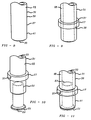
- FIGS. 8-11 The processing steps required to produce the present invention tubular assembly having a bead thereon are shown in FIGS. 8-11.
- Tubular member 31 preferably has outside surface 38 (see FIG. 9) at position 37 which is flush with the cylindrical outside surfaces 39 and 41 longitudinally adjacent thereto; this can best be seen in FIG. 8.
- predetermined position 37 may have circumferential groove 43 formed therein.
- the first step is illustrated in FIG. 9 wherein bushing 17 is installed around outside surface 38 of tubular member 31 at predetermined position 37. At this processing step, bushing 17 fits snugly around outside surface 38, however, bushing 17 can still be forced to move longitudinally along tubular member 15.
- the second processing step is shown in FIG. 10.
- tubular assembly While a number of embodiments of this tubular assembly have been disclosed, it will be appreciated that various modifications may be made without departing from the present invention. For example, multiple seals and multiple bushings may be located longitudinally along the tubular member. Also, the ferrule does not have to contain a flange at the end thereof. Furthermore, while a specific retainer and a specific housing configuration have been shown and described, various other quick connect fasteners or threaded fittings may be used as part of a connector assembly. Moreover, such tubular assemblies may be incorporated into appliances, industrial structures and automotive vehicles.
Landscapes
- General Engineering & Computer Science (AREA)
- Engineering & Computer Science (AREA)
- Mechanical Engineering (AREA)
- Quick-Acting Or Multi-Walled Pipe Joints (AREA)
- Containers And Packaging Bodies Having A Special Means To Remove Contents (AREA)
- Paper (AREA)
- Media Introduction/Drainage Providing Device (AREA)
- Joints With Pressure Members (AREA)
- Mechanical Coupling Of Light Guides (AREA)
- Mutual Connection Of Rods And Tubes (AREA)
- Branch Pipes, Bends, And The Like (AREA)
- Shaping Of Tube Ends By Bending Or Straightening (AREA)
- Coupling Device And Connection With Printed Circuit (AREA)
- Control Of Motors That Do Not Use Commutators (AREA)
- Separation Of Particles Using Liquids (AREA)
- Exhaust Silencers (AREA)
- Joints With Sleeves (AREA)
Claims (11)
- Rohrseitige Anordnung (25, 69, 89, 131) für den Gebrauch zum Transport von Flüssigkeiten in Verbindung mit einem Gehäuse (23), das eine zu deren Aufnahme dienende Buchsenkonfiguration und des weiteren eine zylindrische Innenfläche (40) aufweist, welche darin eine zentrale Durchgangsbohrung definiert, wobei die rohrseitige Anordnung ein rohrförmiges Teil (15, 47, 71, 91, 133), das eine zylindrische Gestalt aufweist und ein männliches Teil darstellt und des weiteren eine Innenfläche (33) und eine Außenfläche (31) und ein distales Ende (35, 73, 107) besitzt und die Außenfläche eine vorbestimmte Position aufweist,dadurch gekennzeichnet,Mittel (19, 83, 95) zum Dichten zwischen dem rohrförmigen Teil (15, 47, 71, 91, 133) und der Innenfläche (40) des Gehäuses (23),eine Buchse (17, 85, 93, 135), die an der vorbestimmten Position (37) entlang der Außenfläche des rohrförmigen Teils positioniert ist und sich passend um diese herum erstreckt und die radiale Ausdehnung des rohrförmigen Teils begrenzt, undeine Hülse (21, 75, 97, 139), die einen Längsabschnitt (51, 77, 99) aufweist, welche eine zylindrische Gestalt hat und in das distale Ende des rohrförmigen Teils eingesetzt ist, wobei das rohrförmige Teil an der vorbestimmten Position durch die Buchse (17, 85, 93, 135) an einer radialen Ausdehnung gehindert ist und die Buchse fest an der vorbestimmten Position (37) auf dem rohrförmigen Teil (15, 47, 71, 91, 133) gehalten ist, umfaßt,daß das rohrförmige Teil (15, 47, 71, 91, 133) aus einem dehnbaren Material besteht,daß die vorbestimmte Position (37) und die Buchse (17, 85, 93, 135) mit einem vorbestimmten Längsabstand von dem distalen Ende angeordnet sind,daß Abschnitte der Innenfläche und der Außenfläche des rohrförmigen Teils (39, 41), die sich in der Längsrichtung neben jeder Seite der vorbestimmten Position (37) befinden, durch den Längsabschnitt (51, 77, 99) der darin befindlichen Hülse im Verhältnis zu der vorbestimmten Position (37) des rohrförmigen Teils, deren radiale Ausdehnung nach außen durch die Buchse (17, 85, 93, 135) begrenzt ist, nach außen verformt sind unddaß die Dichtmittel (19, 83, 95) zwischen der Außenfläche (31) des rohrförmigen Teils und der Innenfläche (40) des Gehäuses (23) abdichten.
- Rohrseitige Anordnung nach Anspruch 1,
wobei die Hülse (21, 75, 97, 139) an ihrem zweiten Ende einen sich nach außen erstreckenden Flansch (61, 79, 101) besitzt und der Flansch der Hülse in der Nähe des distalen Endes (35, 73, 107) des rohrförmigen Teils (15, 47, 71, 91, 133) liegt, nachdem die Hülse darin eingesetzt ist. - Rohrseitige Anordnung nach Anspruch 2,
dadurch gekennzeichnet,
daß der Flansch (79, 101) der Hülse (75, 97) sich radial nach außen über die Außenfläche (31) des rohrförmigen Teils hinaus erstreckt und die Dichtmittel (83, 95) auf diesem dadurch hält, daß die Dichtmittel (83, 95) zwischen der Buchse (85, 93) und dem Flansch der Hülse angeordnet sind. - Rohrseitige Anordnung nach Anspruch 3,
dadurch gekennzeichnet,
daß der Flansch (101) der Hülse (97) einen Lippenabschnitt (103) aufweist, der von einer Umfangskante (105) hervorsteht und sich im wesentlichen normal zu dieser erstreckt. - Rohrseitige Anordnung nach Anspruch 1,
dadurch gekennzeichnet,
daß der Flansch (61) der Hülse (21) sich radial nach außen über die Innenfläche (33) des rohrförmigen Teils (15) hinaus erstreckt und vor dessen Außenfläche (33) endet. - Rohrseitige Anordnung nach einem der vorangehenden Ansprüche,
dadurch gekennzeichnet,
daß Mittel (13) zum Halten des rohrförmigen Teils am Gehäuses vorgesehen sind. - Rohrseitige Anordnung nach Anspruch 6,
wobei die Haltemittel (13) als eine Schnellverbindungs- und Befestigungsvorrichtung dargestellt sind. - Rohrseitige Anordnung nach Anspruch 6,
wobei die Haltemittel als eine Schraubverbindung dargestellt sind. - Rohrseitige Anordnung nach einem der vorangehenden Ansprüche,
dadurch gekennzeichnet,
daß die Außenfläche (45) des rohrförmigen Teils (47) eine in Umfangsrichtung umlaufende Nut (43) aufweist, die an der vorbestimmten Position (37) angebracht ist, und daß die Buchse (17, 85, 93) teilweise in die Nut eingreift, wenn das rohrförmige Teil (47) durch die darin eingesetzte Hülse (21) radial erweitert ist. - Verfahren zum Anbringen einer Wulst um ein rohrförmiges Teil herum,dadurch gekennzeichnet,welcher zur Verwendung in einer rohrseitigen Anordnung, die eine Flüssigkeit transportiert, bestimmt ist und welchesdas Anbringen einer ringförmigen Buchse (17) um ein rohrförmiges Teil, das eine zylindrische Gestalt hat und eine Außenfläche (31) und eine Innenfläche (33) und des weiteren ein distales Ende (35) aufweist, unddas Einsetzen eines Längsabschnitts (51) einer Hülse (21), der zylindrisch ist, in das distale Ende des rohrförmigen Teils umfaßt,daß die Buchse (17) auf dem rohrförmigen Teil an einer vorbestimmt von dem distalen Ende (35) entfernten Position (37) angeordnet wird,daß das rohrförmige Teil (15) erweiterbar ist und daß Abschnitte der Innenfläche (39) und der Außenfläche (41) des rohrförmigen Teil (15), die in Längsrichtung benachbart zu beiden Seiten der Buchse (17) liegen, durch den Längsabschnitt der Hülse geweitet werden und daß die Buchse die radiale Ausdehnung des rohrförmigen Teils an der vorbestimmten Position begrenzt.
- Verfahren nach Anspruch 10,
dadurch gekennzeichnet,daß das rohrförmige Teil (47) an der vorbestimmten Position (37) einer um seinen Umfang herum umlaufende Nut (43) aufweist,daß die Buchse (17) um das rohrförmige Teil (47) herum zur Nut (43) ausgerichtet angebracht ist, unddaß die Buchse (17) teilweise in die Nut (43) eingreift, wenn das rohrförmige Teil (47) durch die darin eingesetzte Hülse (21) radial geweitet wird.
Applications Claiming Priority (4)
| Application Number | Priority Date | Filing Date | Title |
|---|---|---|---|
| WOPCT/US92/08007 | 1992-09-21 | ||
| PCT/US1992/008007 WO1994007077A1 (en) | 1992-09-21 | 1992-09-21 | Means of coupling of non-threaded connections |
| PCT/US1993/006477 WO1994007076A1 (en) | 1992-09-21 | 1993-07-09 | Tubular assembly and method of making same |
| BR9307905A BR9307905A (pt) | 1992-09-21 | 1993-11-29 | Acoplamento de conduto |
Publications (3)
| Publication Number | Publication Date |
|---|---|
| EP0660907A1 EP0660907A1 (de) | 1995-07-05 |
| EP0660907A4 EP0660907A4 (de) | 1996-04-10 |
| EP0660907B1 true EP0660907B1 (de) | 1999-04-21 |
Family
ID=42733760
Family Applications (3)
| Application Number | Title | Priority Date | Filing Date |
|---|---|---|---|
| EP94910266A Expired - Lifetime EP0667942B1 (de) | 1992-09-21 | 1992-09-21 | Kupplungsvorrichtung für gewindelose verbindungen |
| EP93917067A Expired - Lifetime EP0660907B1 (de) | 1992-09-21 | 1993-07-09 | Gesteckte rohranschlussvorrichtung und herstellung |
| EP94904393A Expired - Lifetime EP0731892B1 (de) | 1992-09-21 | 1993-11-29 | Rohrkupplung |
Family Applications Before (1)
| Application Number | Title | Priority Date | Filing Date |
|---|---|---|---|
| EP94910266A Expired - Lifetime EP0667942B1 (de) | 1992-09-21 | 1992-09-21 | Kupplungsvorrichtung für gewindelose verbindungen |
Family Applications After (1)
| Application Number | Title | Priority Date | Filing Date |
|---|---|---|---|
| EP94904393A Expired - Lifetime EP0731892B1 (de) | 1992-09-21 | 1993-11-29 | Rohrkupplung |
Country Status (9)
| Country | Link |
|---|---|
| EP (3) | EP0667942B1 (de) |
| JP (2) | JPH08501378A (de) |
| KR (1) | KR960706620A (de) |
| AT (1) | ATE179245T1 (de) |
| AU (3) | AU687726B2 (de) |
| BR (1) | BR9307905A (de) |
| CA (2) | CA2143213A1 (de) |
| DE (2) | DE69230565T2 (de) |
| WO (3) | WO1994007077A1 (de) |
Families Citing this family (12)
| Publication number | Priority date | Publication date | Assignee | Title |
|---|---|---|---|---|
| US5468028A (en) * | 1994-12-19 | 1995-11-21 | Dana Corporation | Quick connect tube couplings |
| DE29619501U1 (de) * | 1996-11-09 | 1997-01-02 | Rehau Ag + Co, 95111 Rehau | Kupplung für Saug- oder Druckschläuche |
| WO2000034092A2 (en) * | 1998-12-11 | 2000-06-15 | Q3 Jmc, Inc. | Connection cartridge for air tanks |
| US6447022B1 (en) * | 2000-07-31 | 2002-09-10 | Plug Power Inc. | Flexible connector |
| DE202006017177U1 (de) * | 2006-11-10 | 2007-01-18 | Eugster/Frismag Ag | Fluidleitungsverbindungsanordnung |
| DE112008000437A5 (de) * | 2007-03-01 | 2009-12-03 | Luk Lamellen Und Kupplungsbau Beteiligungs Kg | Hydraulisches Element |
| DE102009028473A1 (de) * | 2009-08-12 | 2011-02-17 | Robert Bosch Gmbh | Steckverbindung |
| CN102410418A (zh) * | 2011-09-20 | 2012-04-11 | 蔡应麟 | 一种防止水渗漏的快速接头 |
| DE102012211136A1 (de) * | 2012-06-28 | 2014-01-02 | Robert Bosch Gmbh | Steckverbinder für medienführende Leitungen |
| DE102013215864A1 (de) | 2013-08-12 | 2015-02-12 | Bayerische Motoren Werke Aktiengesellschaft | Dichtungsanordnung für ein Fluid führendes Rohr |
| EP3215779B1 (de) * | 2014-11-05 | 2018-09-05 | Hutchinson | Vorrichtung zur befestigung eines starren steckerendstücks an einem flexiblen aufnahmerohr und herstellungsverfahren dafür |
| US11603952B2 (en) | 2021-07-23 | 2023-03-14 | Cooper-Standard Automotive, Inc. | In-line quick connector |
Family Cites Families (35)
| Publication number | Priority date | Publication date | Assignee | Title |
|---|---|---|---|---|
| US2167258A (en) * | 1936-12-09 | 1939-07-25 | Everlasting Valve Co | Coupling |
| US2521127A (en) * | 1948-05-08 | 1950-09-05 | Wright Aeronautical Corp | Fluid tight joint |
| GB801859A (en) * | 1956-04-24 | 1958-09-24 | Ethel Louie Wigley | Fluid tight joints for pipes |
| US3091483A (en) * | 1960-03-28 | 1963-05-28 | Rain Jet Corp | Flexible pipe connection having line pressure actuated sealing means |
| SE329306B (de) * | 1968-08-30 | 1970-10-05 | Atlas Copco Ab | |
| US3668754A (en) * | 1970-04-22 | 1972-06-13 | Derek Walter Boast | Methods of forming pipe joints |
| US3666297A (en) * | 1971-04-22 | 1972-05-30 | Us Interior | Tube connector fitting |
| US3756632A (en) * | 1971-11-10 | 1973-09-04 | Continental Ind | Coupling apparatus for pipe |
| US3948548A (en) * | 1973-11-10 | 1976-04-06 | Armaturenfabrik Hermann Voss | Hose and pipe coupling |
| US3922011A (en) * | 1973-12-11 | 1975-11-25 | Tom Walters | Hose coupling |
| US3923323A (en) * | 1974-01-02 | 1975-12-02 | Imp Eastman Corp | Tube fitting |
| US4043685A (en) * | 1974-10-22 | 1977-08-23 | Vic-Tree (Mouldings) Limited | Fasteners |
| DE2547411B2 (de) * | 1975-10-23 | 1978-04-27 | Armaturenfabrik Hermann Voss, 5290 Wipperfuerth | Schlauch- und/oder Rohrkupplung |
| US4105226A (en) * | 1976-06-01 | 1978-08-08 | Celanese Corporation | Snap-in fittings and coupling ring therefor |
| US4068863A (en) * | 1976-10-14 | 1978-01-17 | Lasko John A | Pipe joint |
| US4256335A (en) * | 1977-05-23 | 1981-03-17 | Nielsen Jr Anker J | Positive locking terminal bushings for flexible tubing |
| US4191408A (en) * | 1977-05-27 | 1980-03-04 | The Weatherhead Company | Automotive quick connect tube coupling |
| US4243254A (en) * | 1979-01-02 | 1981-01-06 | R. W. Lyall & Co., Inc. | Slip fit type tubing coupling |
| DE2922869A1 (de) * | 1979-06-06 | 1980-12-18 | Voss Armaturen | Verbindungssystem fuer druckleitungen |
| US4526411A (en) * | 1980-10-29 | 1985-07-02 | Proprietary Technology, Inc. | Swivelable quick connector assembly |
| US4352586A (en) * | 1980-12-29 | 1982-10-05 | Ford Motor Company | Linkage system |
| US4643466A (en) * | 1984-03-29 | 1987-02-17 | American Cast Iron Pipe Company | Pipe joint assembly with snap ring and associated method |
| US4637640A (en) * | 1985-02-27 | 1987-01-20 | Aeroquip Corporation | Push-in connect fitting |
| US4844515A (en) * | 1986-02-14 | 1989-07-04 | General Motors Corporation | Fuel connection |
| US4712813A (en) * | 1986-10-28 | 1987-12-15 | Perfection Corporation | Coupling apparatus |
| US4842309A (en) * | 1987-05-20 | 1989-06-27 | Schmelzer Corporation | Quick-connect fluid fitting assembly |
| US4852239A (en) * | 1987-10-26 | 1989-08-01 | Proprietary Technology, Inc. | Method of affixing a ring to plastic pipe |
| US4832378A (en) * | 1988-04-04 | 1989-05-23 | Dura Power Systems Division Of Wickes Manufacturing Company | Fluid duct coupling and snap clip therefor |
| US4828297A (en) * | 1988-06-27 | 1989-05-09 | General Motors Corporation | Fluid coupling |
| DE4033106A1 (de) * | 1989-07-21 | 1992-04-23 | Schaefer Stettiner Schrauben | Anschlussarmatur fuer rohre |
| US5056756A (en) * | 1991-04-24 | 1991-10-15 | U.S. Plastics Corporation | Fluid connector |
| US5207462A (en) * | 1990-11-02 | 1993-05-04 | Proprietary Technology, Inc. | Apparatus and method for a push assemble retaining ring |
| US5110161A (en) * | 1990-11-13 | 1992-05-05 | Proprietary Technology, Inc. | Means of improving performance of swivelling pressure sealing devices |
| US5211427A (en) * | 1990-12-22 | 1993-05-18 | Usui Kokusai Sangyo Kaisha Ltd. | Piping connector |
| US5105787A (en) * | 1991-08-05 | 1992-04-21 | Siemens Automotive L.P. | Internal combustion engine fuel rail assembly joint |
-
1992
- 1992-09-21 WO PCT/US1992/008007 patent/WO1994007077A1/en not_active Ceased
- 1992-09-21 AU AU26996/92A patent/AU687726B2/en not_active Ceased
- 1992-09-21 EP EP94910266A patent/EP0667942B1/de not_active Expired - Lifetime
- 1992-09-21 CA CA002143213A patent/CA2143213A1/en not_active Abandoned
- 1992-09-21 JP JP6508034A patent/JPH08501378A/ja active Pending
- 1992-09-21 DE DE69230565T patent/DE69230565T2/de not_active Expired - Fee Related
-
1993
- 1993-07-09 DE DE69324592T patent/DE69324592T2/de not_active Expired - Fee Related
- 1993-07-09 AT AT93917067T patent/ATE179245T1/de not_active IP Right Cessation
- 1993-07-09 EP EP93917067A patent/EP0660907B1/de not_active Expired - Lifetime
- 1993-07-09 JP JP6508062A patent/JPH08501379A/ja active Pending
- 1993-07-09 AU AU46708/93A patent/AU678981B2/en not_active Ceased
- 1993-07-09 CA CA002143215A patent/CA2143215A1/en not_active Abandoned
- 1993-07-09 WO PCT/US1993/006477 patent/WO1994007076A1/en not_active Ceased
- 1993-11-29 BR BR9307905A patent/BR9307905A/pt not_active IP Right Cessation
- 1993-11-29 AU AU58459/94A patent/AU683637B2/en not_active Ceased
- 1993-11-29 KR KR1019960702822A patent/KR960706620A/ko not_active Ceased
- 1993-11-29 WO PCT/US1993/011622 patent/WO1995014879A1/en not_active Ceased
- 1993-11-29 EP EP94904393A patent/EP0731892B1/de not_active Expired - Lifetime
Also Published As
| Publication number | Publication date |
|---|---|
| EP0731892A1 (de) | 1996-09-18 |
| EP0660907A1 (de) | 1995-07-05 |
| WO1994007076A1 (en) | 1994-03-31 |
| DE69230565D1 (de) | 2000-02-17 |
| WO1994007077A1 (en) | 1994-03-31 |
| CA2143213A1 (en) | 1994-03-31 |
| AU4670893A (en) | 1994-04-12 |
| DE69230565T2 (de) | 2000-07-13 |
| EP0667942B1 (de) | 2000-01-12 |
| DE69324592T2 (de) | 1999-10-14 |
| EP0667942A1 (de) | 1995-08-23 |
| EP0660907A4 (de) | 1996-04-10 |
| AU2699692A (en) | 1994-04-12 |
| EP0731892B1 (de) | 2001-01-17 |
| WO1995014879A1 (en) | 1995-06-01 |
| JPH08501378A (ja) | 1996-02-13 |
| CA2143215A1 (en) | 1994-03-31 |
| EP0667942A4 (de) | 1996-01-10 |
| ATE179245T1 (de) | 1999-05-15 |
| AU5845994A (en) | 1995-06-13 |
| JPH08501379A (ja) | 1996-02-13 |
| AU678981B2 (en) | 1997-06-19 |
| EP0731892A4 (de) | 1997-06-25 |
| DE69324592D1 (de) | 1999-05-27 |
| KR960706620A (ko) | 1996-12-09 |
| BR9307905A (pt) | 1996-08-27 |
| AU683637B2 (en) | 1997-11-20 |
| AU687726B2 (en) | 1998-03-05 |
Similar Documents
| Publication | Publication Date | Title |
|---|---|---|
| US5655796A (en) | Tubular assembly and method of making same | |
| CA2158521C (en) | Quick connect tube couplings | |
| US6062607A (en) | Quick connector with secondary latch confirming feature | |
| EP0459016B1 (de) | Schnellkupplung | |
| CA2135740C (en) | Quick connect cartridge assembly with plug | |
| EP0660907B1 (de) | Gesteckte rohranschlussvorrichtung und herstellung | |
| US5775738A (en) | Means of coupling of non-threaded connections | |
| EP0830538B1 (de) | Hochdruckschnellkupplung zur verwendung in fahrzeugbremsen | |
| US5927761A (en) | Means of coupling of non-threaded connections | |
| US5697652A (en) | Pipe joint assembly | |
| US6234544B1 (en) | Quick connector with confirmation feature | |
| US7434847B2 (en) | Quick connect tube coupling | |
| US4621796A (en) | Airspring with pneumatic fitting | |
| EP1106897B1 (de) | Schnellkupplung für Hochdruck und Montageverfahren | |
| US5193856A (en) | Pipe connector | |
| WO2008077013A2 (en) | Connection of tubes for air conditioning and seal adapted thereto | |
| US20050221679A1 (en) | Quick connector | |
| US6086113A (en) | Means of coupling of non-threaded connections | |
| US4715107A (en) | Method of forming an airspring with pneumatic fitting | |
| EP1177398B1 (de) | Vorrichtung und verfahren zur befestigung eines steifen rohres an einem biegsamen schlauch | |
| CA1320235C (en) | Quick connect pipe coupling | |
| EP0852682A1 (de) | Schnellkupplung mit bestätigung der stellung | |
| KR100215703B1 (ko) | 관 조립체 및 그 제작방법 | |
| MXPA98002365A (en) | Fast connector with confirmac features | |
| EP0909916A2 (de) | Kupplungsvorrichtung für gewindelose Verbindungen |
Legal Events
| Date | Code | Title | Description |
|---|---|---|---|
| PUAI | Public reference made under article 153(3) epc to a published international application that has entered the european phase |
Free format text: ORIGINAL CODE: 0009012 |
|
| 17P | Request for examination filed |
Effective date: 19950309 |
|
| AK | Designated contracting states |
Kind code of ref document: A1 Designated state(s): AT BE CH DE DK ES FR GB GR IE IT LI LU MC NL PT SE |
|
| A4 | Supplementary search report drawn up and despatched | ||
| AK | Designated contracting states |
Kind code of ref document: A4 Designated state(s): AT BE CH DE DK ES FR GB GR IE IT LI LU MC NL PT SE |
|
| RAP1 | Party data changed (applicant data changed or rights of an application transferred) |
Owner name: PROPRIETARY TECHNOLOGY, INC. |
|
| 17Q | First examination report despatched |
Effective date: 19970428 |
|
| GRAG | Despatch of communication of intention to grant |
Free format text: ORIGINAL CODE: EPIDOS AGRA |
|
| GRAG | Despatch of communication of intention to grant |
Free format text: ORIGINAL CODE: EPIDOS AGRA |
|
| GRAH | Despatch of communication of intention to grant a patent |
Free format text: ORIGINAL CODE: EPIDOS IGRA |
|
| GRAH | Despatch of communication of intention to grant a patent |
Free format text: ORIGINAL CODE: EPIDOS IGRA |
|
| GRAA | (expected) grant |
Free format text: ORIGINAL CODE: 0009210 |
|
| REF | Corresponds to: |
Ref document number: 179245 Country of ref document: AT Date of ref document: 19990515 Kind code of ref document: T |
|
| REG | Reference to a national code |
Ref country code: CH Ref legal event code: EP |
|
| RBV | Designated contracting states (corrected) |
Designated state(s): DE FR GB IT |
|
| REG | Reference to a national code |
Ref country code: IE Ref legal event code: FG4D |
|
| RIN2 | Information on inventor provided after grant (corrected) |
Free format text: BARTHOLOMEW, DONALD DEKLE |
|
| REF | Corresponds to: |
Ref document number: 69324592 Country of ref document: DE Date of ref document: 19990527 |
|
| ET | Fr: translation filed | ||
| NLV5 | Nl: annulment (art. 75) | ||
| PLBE | No opposition filed within time limit |
Free format text: ORIGINAL CODE: 0009261 |
|
| STAA | Information on the status of an ep patent application or granted ep patent |
Free format text: STATUS: NO OPPOSITION FILED WITHIN TIME LIMIT |
|
| 26N | No opposition filed | ||
| REG | Reference to a national code |
Ref country code: IE Ref legal event code: MM4A |
|
| PGFP | Annual fee paid to national office [announced via postgrant information from national office to epo] |
Ref country code: FR Payment date: 20000619 Year of fee payment: 8 |
|
| REG | Reference to a national code |
Ref country code: GB Ref legal event code: IF02 |
|
| PG25 | Lapsed in a contracting state [announced via postgrant information from national office to epo] |
Ref country code: FR Free format text: LAPSE BECAUSE OF NON-PAYMENT OF DUE FEES Effective date: 20020329 |
|
| REG | Reference to a national code |
Ref country code: FR Ref legal event code: ST |
|
| PGFP | Annual fee paid to national office [announced via postgrant information from national office to epo] |
Ref country code: GB Payment date: 20020613 Year of fee payment: 10 |
|
| PGFP | Annual fee paid to national office [announced via postgrant information from national office to epo] |
Ref country code: DE Payment date: 20020731 Year of fee payment: 10 |
|
| PG25 | Lapsed in a contracting state [announced via postgrant information from national office to epo] |
Ref country code: GB Free format text: LAPSE BECAUSE OF NON-PAYMENT OF DUE FEES Effective date: 20030709 |
|
| PG25 | Lapsed in a contracting state [announced via postgrant information from national office to epo] |
Ref country code: DE Free format text: LAPSE BECAUSE OF NON-PAYMENT OF DUE FEES Effective date: 20040203 |
|
| GBPC | Gb: european patent ceased through non-payment of renewal fee |
Effective date: 20030709 |
|
| PG25 | Lapsed in a contracting state [announced via postgrant information from national office to epo] |
Ref country code: IT Free format text: LAPSE BECAUSE OF NON-PAYMENT OF DUE FEES Effective date: 20050709 |