EP0661455A1 - Aktiver oder passiver Strömungsverteiler - Google Patents
Aktiver oder passiver Strömungsverteiler Download PDFInfo
- Publication number
- EP0661455A1 EP0661455A1 EP94830564A EP94830564A EP0661455A1 EP 0661455 A1 EP0661455 A1 EP 0661455A1 EP 94830564 A EP94830564 A EP 94830564A EP 94830564 A EP94830564 A EP 94830564A EP 0661455 A1 EP0661455 A1 EP 0661455A1
- Authority
- EP
- European Patent Office
- Prior art keywords
- crown wheel
- flow divider
- chamber
- fluid
- toothed
- Prior art date
- Legal status (The legal status is an assumption and is not a legal conclusion. Google has not performed a legal analysis and makes no representation as to the accuracy of the status listed.)
- Withdrawn
Links
- 239000012530 fluid Substances 0.000 claims abstract description 23
- 238000012384 transportation and delivery Methods 0.000 claims abstract description 19
- 238000005096 rolling process Methods 0.000 claims description 3
- 239000000725 suspension Substances 0.000 claims description 2
- 239000002131 composite material Substances 0.000 claims 1
- 238000011144 upstream manufacturing Methods 0.000 description 4
- 230000000694 effects Effects 0.000 description 1
- 238000004519 manufacturing process Methods 0.000 description 1
Images

Classifications
-
- F—MECHANICAL ENGINEERING; LIGHTING; HEATING; WEAPONS; BLASTING
- F04—POSITIVE - DISPLACEMENT MACHINES FOR LIQUIDS; PUMPS FOR LIQUIDS OR ELASTIC FLUIDS
- F04C—ROTARY-PISTON, OR OSCILLATING-PISTON, POSITIVE-DISPLACEMENT MACHINES FOR LIQUIDS; ROTARY-PISTON, OR OSCILLATING-PISTON, POSITIVE-DISPLACEMENT PUMPS
- F04C2/00—Rotary-piston machines or pumps
- F04C2/08—Rotary-piston machines or pumps of intermeshing-engagement type, i.e. with engagement of co-operating members similar to that of toothed gearing
- F04C2/12—Rotary-piston machines or pumps of intermeshing-engagement type, i.e. with engagement of co-operating members similar to that of toothed gearing of other than internal-axis type
- F04C2/14—Rotary-piston machines or pumps of intermeshing-engagement type, i.e. with engagement of co-operating members similar to that of toothed gearing of other than internal-axis type with toothed rotary pistons
Definitions
- the present invention concerns a flow divider designed to divide a single flow of fluid into a number of separate flows of fluid flowing out of a dividing chamber.
- multistage flow dividers on the one hand and inside-gear pumps on the other hand are known in the field of hydraulic systems.
- Such dividers generally comprise several in-line dividing stages, connected to and controlled by common shafts. Their lengths and sizes are always considerable and proportional to the number of stages. Besides, they always require a pump upstream, which supplies the flow to be divided through the various consecutive stages.
- the inside-gear pumps are usually single-stage and unable for multiple division of the outflowing fluid.
- Another object of the invention is to provide a flow divider in which both the division point and the outlet points of separate flows of fluid are distributed in a circle, around a centre axis, and are not in line on the same axis as in known dividers.
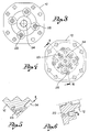
- the device includes a casing 10 constituted preferably by two semi-bodies 11, 12 pack-connected to each other, with an intermediate annular element 13.
- the casing 10 defines a circular chamber 14 including a crown wheel toothed inside 15 whose X axis coincides with the casing axis.
- the crown wheel 15 is rotably supported between both half-bodies 11,12 and peripherally it is supported by the annular element 13.
- the crown wheel 15 may be mounted on hydraulic suspensions or on rolling bodies - not illustrated.
- toothed wheels 16 - four in the embodiment described herein - are arranged angularly spaced from one another, along a circumference which is concentric with the crown wheel 15.
- Each toothed wheel 16 is supported by a shaft 17 mounted between the semi-bodies 11,12, parallelly to the X axis of said crown wheel 15.
- the assembly is such - see Figures 1 and 2 - that the toothed wheels 16 engage with the crown wheel toothed inside 15 and rotate accordingly on the respective shafts 17.
- a stationary deflector element 18 is fixed to one of the semi-bodies in 18'.
- the deflector element 18 comprises a first wall 19 tangent to the crests of the toothed wheel 16 so as to define, with some of the teeth thereof, a first delivery chamber 20, and a second wall 21 tangent to the crests of the crown wheel 15 so as to define, with some of the teeth thereof, a second delivery chamber 22.
- fluid inlet/suction holes 23 branching out from a centre hole 24 - see Figures 4 and 5 - which is connected to a fluid delivery duct according to arrow E .
- every two delivery chambers 20,22 defined by each deflector element 18 converge in a fluid outlet/delivery hole 25 provided in such a semi-body (12) on a level where the teeth of the crown wheel 15 and of the wheel 16 are engaged - see Figures 4 and 6.
- the outlet/delivery holes 25 are connected to ducts which permit delivery of fluid to users, according to arrow U in Fig. 6.
- every toothed wheel 16 interacts with the crown wheel and with a deflector thus constituting a dividing stage.
- an active divider by simply adding a centre gear 26, which engages with all the toothed wheels 16 and which is connected to and actuated with a control shaft 27 on the X axis, as shown in Figures 7 and 8.
- the shaft may receive rotary motion from a power take-off, whereas the gear 26 connected thereto controls rotation of the toothed wheels 16 and, through them, of the crown wheel 15.
- Fluid inlet and division towards the points of use are performed as described above, but no pumps are required upstream, pump effect being achieved by integrating the centre gear 26 with the toothed wheels 16 connected thereto.
- the same embodiment may also be used as a multistage pump in order to suck the fluid through the holes 23 and deliver it through the holes 25, with the possibility of adding up outlet deliveries downstream the device.
- engaging teeth are also used to compress fluid like in a gear pump.
- the assembly in the embodiment shown in Figures 7 and 8, may also be used as a hydraulic motor, by simply causing inverse rotation of the rotating elements, with the fluid being sucked through the holes 23 and delivered through the holes 25, and namely as a variable-torque hydraulic motor by varying the number of the stages employed.
- side walls may be provided on a level with the delivery chambers 20,22 of each dividing stage, such walls being fixed in sliding contact with the rotating elements or movable, for movable o pressure balanced contact with the said elements.
Landscapes
- Engineering & Computer Science (AREA)
- Mechanical Engineering (AREA)
- General Engineering & Computer Science (AREA)
- Rotary Pumps (AREA)
- Hydraulic Motors (AREA)
- Details And Applications Of Rotary Liquid Pumps (AREA)
- Bipolar Transistors (AREA)
Applications Claiming Priority (2)
| Application Number | Priority Date | Filing Date | Title |
|---|---|---|---|
| ITBS930123 | 1993-12-07 | ||
| ITBS930123A IT1263567B (it) | 1993-12-07 | 1993-12-07 | Dispositivo ripartizione di flusso attivo o passivo |
Publications (1)
| Publication Number | Publication Date |
|---|---|
| EP0661455A1 true EP0661455A1 (de) | 1995-07-05 |
Family
ID=11345196
Family Applications (1)
| Application Number | Title | Priority Date | Filing Date |
|---|---|---|---|
| EP94830564A Withdrawn EP0661455A1 (de) | 1993-12-07 | 1994-12-06 | Aktiver oder passiver Strömungsverteiler |
Country Status (2)
| Country | Link |
|---|---|
| EP (1) | EP0661455A1 (de) |
| IT (1) | IT1263567B (de) |
Cited By (2)
| Publication number | Priority date | Publication date | Assignee | Title |
|---|---|---|---|---|
| WO2002077416A3 (en) * | 2001-03-21 | 2003-03-20 | Dennis G Ewald | Center driven pressure clamped pump |
| EP2055954A4 (de) * | 2006-08-23 | 2012-11-14 | Ihi Corp | Dreifach gekröpfte zahnradpumpe |
Citations (5)
| Publication number | Priority date | Publication date | Assignee | Title |
|---|---|---|---|---|
| US2457465A (en) * | 1946-04-27 | 1948-12-28 | Cread Engineering And Res Comp | Variable displacement gear pump |
| DE871692C (de) * | 1951-09-11 | 1953-03-26 | Zahnraederfabrik Augsburg Vorm | Zahnradpumpe |
| GB870019A (en) * | 1953-05-19 | 1961-06-07 | Chemstrand Corp | Improvements in rotary meters and pumps |
| FR2089179A5 (de) * | 1970-04-04 | 1972-01-07 | Ct Tech Okretowej | |
| DE2100403A1 (de) * | 1971-01-07 | 1972-07-20 | Joseph Lucas (Industries) Ltd., Birmingham (Grossbritannien) | Rotierende Hydraulikmaschine |
-
1993
- 1993-12-07 IT ITBS930123A patent/IT1263567B/it active IP Right Grant
-
1994
- 1994-12-06 EP EP94830564A patent/EP0661455A1/de not_active Withdrawn
Patent Citations (5)
| Publication number | Priority date | Publication date | Assignee | Title |
|---|---|---|---|---|
| US2457465A (en) * | 1946-04-27 | 1948-12-28 | Cread Engineering And Res Comp | Variable displacement gear pump |
| DE871692C (de) * | 1951-09-11 | 1953-03-26 | Zahnraederfabrik Augsburg Vorm | Zahnradpumpe |
| GB870019A (en) * | 1953-05-19 | 1961-06-07 | Chemstrand Corp | Improvements in rotary meters and pumps |
| FR2089179A5 (de) * | 1970-04-04 | 1972-01-07 | Ct Tech Okretowej | |
| DE2100403A1 (de) * | 1971-01-07 | 1972-07-20 | Joseph Lucas (Industries) Ltd., Birmingham (Grossbritannien) | Rotierende Hydraulikmaschine |
Cited By (3)
| Publication number | Priority date | Publication date | Assignee | Title |
|---|---|---|---|---|
| WO2002077416A3 (en) * | 2001-03-21 | 2003-03-20 | Dennis G Ewald | Center driven pressure clamped pump |
| EP2055954A4 (de) * | 2006-08-23 | 2012-11-14 | Ihi Corp | Dreifach gekröpfte zahnradpumpe |
| US8672657B2 (en) | 2006-08-23 | 2014-03-18 | Ihi Corporation | Double gear pump with improved bearings |
Also Published As
| Publication number | Publication date |
|---|---|
| IT1263567B (it) | 1996-08-27 |
| ITBS930123A0 (it) | 1993-12-07 |
| ITBS930123A1 (it) | 1995-06-07 |
Similar Documents
| Publication | Publication Date | Title |
|---|---|---|
| US4025225A (en) | Disc pump or turbine | |
| EP0155419B1 (de) | Schallminderungseinrichtung für Flüssigkeitsring-Pumpen mit konisch angeordneten Durchlässen | |
| US7011491B2 (en) | Friction vacuum pump | |
| WO1993023672A1 (de) | Gasreibungsvakuumpumpe | |
| DE19632375A1 (de) | Gasreibungspumpe | |
| US6359411B1 (en) | Displacement machine for compressible media | |
| WO1995003478A1 (en) | Synchronizer assembly for a scroll fluid device | |
| US4893985A (en) | Multi-stage molecular pump | |
| US5108273A (en) | Helical metering pump having different sized rotors | |
| US6857441B2 (en) | Fluid metering device | |
| US6471497B2 (en) | Gas supplying device for vacuum pump | |
| JPH109363A (ja) | 改良駆動システム | |
| US6969242B2 (en) | Compressor | |
| EP0661455A1 (de) | Aktiver oder passiver Strömungsverteiler | |
| CN1878652A (zh) | 齿轮泵 | |
| EP1243796B1 (de) | Vakuumpumpe | |
| US5096398A (en) | Pulse tuned optimized positive displacement porting | |
| JPS63500112A (ja) | 潤滑油ポンプと潤滑油通路を備えた内燃機関 | |
| US3473437A (en) | Rotary slide valve for fluid motors and pumps | |
| WO2008031819A1 (de) | Vakuumpumpe | |
| DE2409857B2 (de) | Turbomolekularvakuumpumpe mit zumindest teilweise glockenfoermig ausgebildetem rotor | |
| AU617002B2 (en) | Improvements relating to gerotor pumps | |
| EP1081387B1 (de) | Vakuumpumpe | |
| EP0841485B1 (de) | Pumpe mit regelbarer Durchflussmenge | |
| GB2110759A (en) | Rotary positive-displacement fluid-machines |
Legal Events
| Date | Code | Title | Description |
|---|---|---|---|
| PUAI | Public reference made under article 153(3) epc to a published international application that has entered the european phase |
Free format text: ORIGINAL CODE: 0009012 |
|
| AK | Designated contracting states |
Kind code of ref document: A1 Designated state(s): BE DE ES FR GB IE NL SE |
|
| 17P | Request for examination filed |
Effective date: 19951028 |
|
| 17Q | First examination report despatched |
Effective date: 19960705 |
|
| STAA | Information on the status of an ep patent application or granted ep patent |
Free format text: STATUS: THE APPLICATION IS DEEMED TO BE WITHDRAWN |
|
| 18D | Application deemed to be withdrawn |
Effective date: 19971104 |