EP0661841B1 - Paritäts- und Syndromgenerator zur Fehler-Erkennung und -Korrektur in digitalen Übertragungssystemen - Google Patents
Paritäts- und Syndromgenerator zur Fehler-Erkennung und -Korrektur in digitalen Übertragungssystemen Download PDFInfo
- Publication number
- EP0661841B1 EP0661841B1 EP94309850A EP94309850A EP0661841B1 EP 0661841 B1 EP0661841 B1 EP 0661841B1 EP 94309850 A EP94309850 A EP 94309850A EP 94309850 A EP94309850 A EP 94309850A EP 0661841 B1 EP0661841 B1 EP 0661841B1
- Authority
- EP
- European Patent Office
- Prior art keywords
- polynomial
- decoding
- error
- updating
- degree
- Prior art date
- Legal status (The legal status is an assumption and is not a legal conclusion. Google has not performed a legal analysis and makes no representation as to the accuracy of the status listed.)
- Expired - Lifetime
Links
- 238000004891 communication Methods 0.000 title claims description 26
- 208000011580 syndromic disease Diseases 0.000 title claims description 25
- 238000012937 correction Methods 0.000 title description 7
- 238000001514 detection method Methods 0.000 title description 3
- 238000000034 method Methods 0.000 claims description 51
- 238000004590 computer program Methods 0.000 claims 1
- 238000012545 processing Methods 0.000 description 100
- 238000004364 calculation method Methods 0.000 description 51
- 238000003672 processing method Methods 0.000 description 12
- 238000010586 diagram Methods 0.000 description 7
- 230000003247 decreasing effect Effects 0.000 description 6
- 230000007423 decrease Effects 0.000 description 5
- 239000011159 matrix material Substances 0.000 description 4
- 238000012360 testing method Methods 0.000 description 4
- 238000013459 approach Methods 0.000 description 2
- 238000012850 discrimination method Methods 0.000 description 2
- 238000007476 Maximum Likelihood Methods 0.000 description 1
- 238000007792 addition Methods 0.000 description 1
- 230000006870 function Effects 0.000 description 1
- 238000012986 modification Methods 0.000 description 1
- 230000004048 modification Effects 0.000 description 1
- 238000006467 substitution reaction Methods 0.000 description 1
Images




Classifications
-
- H—ELECTRICITY
- H04—ELECTRIC COMMUNICATION TECHNIQUE
- H04L—TRANSMISSION OF DIGITAL INFORMATION, e.g. TELEGRAPHIC COMMUNICATION
- H04L1/00—Arrangements for detecting or preventing errors in the information received
- H04L1/004—Arrangements for detecting or preventing errors in the information received by using forward error control
- H04L1/0056—Systems characterized by the type of code used
- H04L1/0057—Block codes
-
- H—ELECTRICITY
- H03—ELECTRONIC CIRCUITRY
- H03M—CODING; DECODING; CODE CONVERSION IN GENERAL
- H03M13/00—Coding, decoding or code conversion, for error detection or error correction; Coding theory basic assumptions; Coding bounds; Error probability evaluation methods; Channel models; Simulation or testing of codes
- H03M13/03—Error detection or forward error correction by redundancy in data representation, i.e. code words containing more digits than the source words
- H03M13/05—Error detection or forward error correction by redundancy in data representation, i.e. code words containing more digits than the source words using block codes, i.e. a predetermined number of check bits joined to a predetermined number of information bits
- H03M13/13—Linear codes
- H03M13/15—Cyclic codes, i.e. cyclic shifts of codewords produce other codewords, e.g. codes defined by a generator polynomial, Bose-Chaudhuri-Hocquenghem [BCH] codes
- H03M13/151—Cyclic codes, i.e. cyclic shifts of codewords produce other codewords, e.g. codes defined by a generator polynomial, Bose-Chaudhuri-Hocquenghem [BCH] codes using error location or error correction polynomials
-
- H—ELECTRICITY
- H04—ELECTRIC COMMUNICATION TECHNIQUE
- H04L—TRANSMISSION OF DIGITAL INFORMATION, e.g. TELEGRAPHIC COMMUNICATION
- H04L1/00—Arrangements for detecting or preventing errors in the information received
- H04L1/004—Arrangements for detecting or preventing errors in the information received by using forward error control
- H04L1/0045—Arrangements at the receiver end
Definitions
- the present invention relates to a communication method, which corrects, at a receiving side, a data error caused by a communication path or a storage medium in a digital communication system and a digital storage system, and an apparatus therefor.
- Decoding methods of error-correcting codes can be classified into hard decision decoding methods and soft decision decoding methods.
- a hard decision decoding method is a method of performing error correction for a digital sequence obtained by hard-deciding a reception signal to "0" and "1". Since the arrangement of a decoder is simple, this method is widely used for various media such as a CD (Compact Disk).
- a soft decision decoding method an analog weight indicating a probability of a digital sequence obtained by soft-deciding a reception signal is calculated in addition to the digital sequence, and error correction is performed by utilizing the analog weight. For this reason, this method can sufficiently bring out the capability of error-correcting codes, and can improve the S/N ratio by about 2 to 3 dB as compared to the hard decision decoding method.
- a GMD (Generalized Minimum Distance) decoding method to be described below is one of the soft decision decoding methods, and is known as a decoding method which can almost perform maximum likelihood decoding using an analog weight. If the minimum distance of codes is represented by d, the conventional GMD decoding can correct a maximum of (d-1) errors, and can realize error correction about twice the correction capability obtained by a single hard decision decoding cycle.
- the present invention has been made in consideration of the above-mentioned prior arts, and has its object to provide an improved communication method and an apparatus therefor.
- a decoder for decoding an encoded received word by generalized minimum distance decoding using a remainder decoding algorithm comprising:
- a decoder for decoding an encoded received word by generalized minimum distance decoding using a remainder decoding algorithm comprising:
- a decoding method for decoding an encoded received word by generalized minimum distance decoding using a remainder decoding algorithm comprising:
- a method for decoding an encoded received word by generalized minimum distance decoding using a remainder decoding algorithm comprising:
- a GMD decoding method and an apparatus therefor according to the first embodiment of the present invention will be described below. First, an outline of the GMD decoding method will be briefly described below, and thereafter, a description of the main subject will be given.
- the GMD decoding can correct a maximum of (d-1) errors, and can realize error correction about twice the correction capability by a single hard decision decoding cycle.
- the GMD decoding requires a maximum of (d-1)/2 hard decision decoding cycles, a larger computational complexity is required than the hard decision decoding method which requires only a single decoding cycle, and this method is not used often in practice.
- E. R. Berlekamp proposed a remainder decoding method executed using a remainder polynomial obtained by dividing a received sequence by a generator polynomial of codes, and suggested a possibility of a great decrease in computational complexity required for the GMD decoding if the remainder decoding method was applied to the GMD decoding. Furthermore, E. R. Berlekamp proposed the following algorithm, called a Welch-Berlekamp (WB) algorithm, which efficiently executed remainder decoding. Since then, Morii, Araki, et. al.
- decoding processing based on the algorithm of the conventional GMD decoding does not consider the computational complexity for degrees.
- the decoding processing based on the WB algorithm requires two multipliers 30 and 31 for respectively performing multiplications with a j and b j and two degree check circuits 32 and 33 for checking the degrees of polynomials U j (x) and Q j (x), as shown in Fig. 2, so as to perform discrimination in 4).
- this technique can be applied to decoding processing based on a recursive WB algorithm (to be described later), and decoding processing with a minimum computational complexity as a whole can be realized.
- the discrimination method in the decoding processing which can be realized by a degree check circuit of a polynomial as a feature of the first embodiment will be described below.
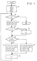
- the decoding processing method of the first embodiment will be described below with reference to the flow chart in Fig. 1.
- This decoding processing method can achieve calculations at a higher speed by a smaller number of circuit components than the conventional WB algorithm since it need not check the degree of the polynomial Q j (x).
- G(x) (x - ⁇ b )•(x - ⁇ b+1 )•••(x - ⁇ b+d-2 )
- N means the error-correcting capability of codes.
- a scalar quantity a j is calculated from the error evaluator polynomial V j (x), the error locator polynomial U j (x), and a syndrome polynomial S(x). Also, a scalar quantity b j is calculated from the auxiliary error evaluator polynomial Q j (x), the auxiliary error locator polynomial P j (x), and the syndrome polynomial S(x).
- x j is numbered by j in the order of lower reliability levels.
- step S7 "j+1"-th degree polynomials V j+1 (x), U j+1 (x), Q j+1 (x), and P j+1 (x) are calculated from j-th degree polynomials, and a j and b j .
- step S9 j is incremented by 1, and the processing from step S2 is repeated.
- Reed-Solomon codes can be decoded by simpler calculations than in the decoding method using the conventional WB algorithm.
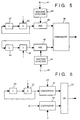
- the discrimination processing in step S6 can be realized by, e.g., the circuit arrangement shown in Fig. 3.
- an OR circuit 2 can be realized by a 1-bit OR gate. Therefore, only one degree check circuit for the polynomial U j (x) is required, and the circuit arrangement is simple as a whole.
- the degree checking can be realized with a smaller computational complexity. The superiority of this arrangement can be clearly recognized upon comparison with the circuit shown in Fig. 2. Referring to Fig.
- high-speed decoding processing can be realized by simple calculations as compared to decoding processing based on the conventional WB algorithm.
- the recursive WB algorithm is as follows.
- the decoding processing based on the recursive WB algorithm adopts the circuit arrangement for supporting discrimination processing in 40), as shown in Fig. 5.
- reference numerals 47 and 48 denote registers for respectively storing temporary values of L and L'.
- Adders 50 and 49 respectively increment L and L' stored in the registers 47 and 48 by 1.
- Non-zero detection circuits 43 and 44 are circuits for respectively detecting if values a j and b j are non-zero. If these values are non-zero, the values are supplied to AND circuits 45 and 46, and are logically ANDed to the output values L and L' from the adders 50 and 49, respectively.
- the outputs from the AND circuits 45 and 46 are values indicating the degrees of a j •x L' and b j •x L . These degrees are compared by a comparator 40, and a comparison result is output.
- the decoding processing method of the second embodiment can execute decoding processing based on the recursive WB algorithm at a higher speed by simpler calculations, and will be described below with reference to the flow chart in Fig. 4.
- a calculation associated with L' corresponding to the degree of a polynomial Q j (x) need not be performed as compared to the decoding processing based on the recursive WB algorithm.
- an error locator polynomial U j (x) and an auxiliary error locator polynomial P j (x) are initialized to "0”
- an error evaluator polynomial V j (x) and an auxiliary error evaluator polynomial Q j (x) are initialized to "1".
- P j (x), Q j (x), U j (x), and V j (x) are expressed as elements of a matrix P. L representing the degree of each of the polynomials Q j (x) and U j (x) is initialized to "0".
- N means the error-correcting capability of codes.
- step S15 It is checked in step S15 if a j is "0" or L is larger than "j/2". If L is smaller than "j/2", the flow advances to step S16. Otherwise, the flow advances to step S17 to set a matrix Y as follows, and to increment L by 1:
- step S16 the matrix Y is set as follows:
- step S18 updating calculations of the matrices P and ⁇ are performed.
- step S19 j is incremented by 1, and processing steps from step S11 are executed.
- Decoded data are generated based on the error locator polynomial and the error evaluator polynomial which are obtained, as described above.
- Reed-Solomon codes can be decoded by simpler calculations than in the decoding method using the conventional recursive WB algorithm.
- the discrimination processing in step S15 in the second decoding processing method can be realized by, e.g., the circuit arrangement shown in Fig. 6.
- a comparator 22 compares a j and "0", and outputs the comparison result to an OR circuit 20.
- a register 24 stores a temporary value L. This L is incremented by an adder 23, and is output to a comparator 21 and the register 24.
- the register 24 stores the incremented value L.
- the comparator 21 compares the incremented value L and "j/2", and outputs the comparison result to the OR circuit 20.
- the OR circuit 20 receives the outputs from the comparators 21 and 22, logically ORs these outputs, and outputs a calculation result.
- degree processing can be realized by a smaller circuit with a smaller computational complexity. More specifically, from the circuit arrangement for degree processing based on the recursive algorithm, at least the register 48 and the adder 49 associated with L' can be omitted.
- the degree of Q j (x) is expressed by the degree of U j (x).
- checking (calculation) of the degree (L) of U j (x) can be omitted.
- P j (x) and U j (x) represent error locator polynomials
- Q j (x) and V j (x) represent error evaluator polynomials. Since Q j (x) is no longer related to control of the algorithm according to the present invention, if error evaluator polynomials are not necessary like in BCH codes, Q j (x) and V j (x) themselves can be omitted, and the computational complexity can be further decreased.
- the computational complexity associated with the degree can be decreased, and a GMD decoding algorithm with a minimum total computational complexity can be realized.
- Q j (x) and V j (x) need not be calculated, and the computational complexity can be further decreased.
- Fig. 7 will be briefly described below.
- the time base of the calculations is plotted along an abscissa 70.
- Variables for decoding processing using the WB algorithm are plotted along an ordinate 71.
- the calculation order is as follows. First, a 0 and b 0 are calculated, and P 1 , Q 1 , U 1 , and V 1 are then calculated using these values.
- a 1 and b 1 are calculated from P 1 , Q 1 , U 1 , and V 1 .
- P 2 , Q 2 , U 2 , and V 2 are calculated to calculate a 2 and b 2 ,..., and finally, P p , Q p , U p , and V p are calculated.
- the third embodiment has as its object to provide a parallel decoding processing method which can realize high-speed decoding processing.
- the parallel decoding processing method of the third embodiment will be described in detail below.
- a j and b j can be (x v •y j )-th degree coefficients of the polynomials C(x,y) and D(x,y) .
- C(x,y) and D(x,y) can be updated as follows:
- the WB algorithm can be modified as follows:
- Fig. 8 is a flow chart showing the decoding processing of the above-mentioned decoding algorithm of the third embodiment. The decoding processing will be described below with reference to this flow chart.
- step S82 the (x v •y j )-th degree coefficient of C j (x,y) is set to be a j . Also, the (x v •y j )-th degree coefficient of D j (x,y) is set to be b j .
- step S85 the degree of a j •Q j (x) is compared with the degree of b j •U j (x). If the degree of a j •Q j (x) is smaller than the degree of b j •U j (x), the flow advances to step S86; otherwise, the flow advances to step S87.
- steps S86 and S87 the updating calculations of the polynomials described in the corresponding steps in Fig. 8 are executed.
- step S88 j is incremented by 1, and the flow returns to step S81 to repeat the above processing.
- a j and b j are the (x v •y j )-th degree coefficients of C j (x,y) and D j (x,y). If C j+1 (x,y) or D j+1 (x,y) is sequentially calculated from higher degrees toward lower degrees using C j (x,y) and D j (x,y), the calculations of the (j+1)-th degree polynomials can be started when the (x v •y j )-th degree coefficients of C j (x,y) and D j (x,y) are obtained.
- the decoding processing of the third embodiment can be realized by, e.g., an apparatus shown in Fig. 11
- the respective processing units will be described below.
- a memory 110 stores initial values and their updated values set in step S80.
- the memory 110 is accessed by a control circuit 112 and a polynomial calculation processing circuit 111, as needed.
- the control circuit 112 performs the following control. That is,
- the polynomial calculation processing circuit 111 executes the selected processing, i.e., calculation processing in step S86 or S87, on the basis of the processing request from the control circuit 112.
- control circuit 112 and the polynomial calculation processing circuit 111 need not be separated since they can be executed in a software manner using, e.g., a CPU. Since calculations required in the control circuit 112 and the polynomial calculation processing circuit 111 are simple multiplications/divisions and additions/subtractions of integers, no special processing circuit is required.
- C j (x,y) and D j (x,y) are used for calculating a j and b j as their (x v •y j )-th degree coefficients, and other coefficients are not necessary. Therefore, as described in a well-known continued fraction method (see L. R. Welch and R. A. Scholtz: "Continued fractions and Berlekamp's algorithm", IEEE Trans. Inf. Theory, IT-25, pp. 19-27, Jan 1979), calculations which are not related to the final result can be omitted, and the total computational complexity can be reduced.
- the present invention may be applied to either a system constituted by a plurality of devices or an apparatus consisting of a single device. Also, the present invention may be applied to a case wherein the invention is achieved by supplying a program to a system or apparatus, as a matter of course.
- a high-speed algorithm often means one with a smaller computational complexity.
- an approach which decreases the computational complexity of the algorithm and an approach which improves the degree of parallelism of the algorithm are available. This is because the processing time can be shorted by simultaneously executing a plurality of processing operations by parallel processing.
- a large-scale parallel processing chip can be easily realized due to the recent advance of VLSI techniques. Therefore, an algorithm with a high degree of parallelism is often suitable for high-speed processing.
- the third embodiment is an example of the invention made in consideration of the background that a parallel processing circuit can be realized with low cost due to the advance of the VLSI techniques.
- the decoding processing method of the third embodiment higher-speed-processing with a higher degree of parallelism than the conventional WB algorithm can be realized.
- the conventional WB algorithm requires two different kinds of calculations, i.e., the updating calculations of polynomials and the substitution calculations for calculating a j and b j , while the decoding processing method of the third embodiment requires only the updating calculations of polynomials, thus realizing a simple communication apparatus which can perform high-speed decoding.
- the decoding method and apparatus for communication codes have been described.
- an example of a communication apparatus which comprises these decoding method and apparatus will be described.
- Fig. 12 is a schematic block diagram showing the arrangement of a communication apparatus 120 according to the fourth embodiment.
- the communication apparatus 120 of the fourth embodiment will be described below with reference to Fig. 12.
- a CPU 121 controls the entire communication apparatus 120.
- a control program is pre-stored in a ROM 124, and the CPU 121 executes this control program.
- a keyboard 122 is an input terminal for inputting commands and data for the communication apparatus 120.
- a RAM 123 stores work data and communication data with which the CPU 121 executes various kinds of processing.
- a monitor 125 displays various kinds of processing results in the communication apparatus 120, communication data, input commands from the keyboard 122, and the like.
- An encoder 127 performs encoding processing of communication data stored in the RAM 123, and outputs encoded data onto a communication line 129.
- a decoder 126 decodes encoded data transmitted from an external communication apparatus via a communication line 128, and stores decoded data in the RAM 123.
- the decoder 126 is a portion for performing decoding processing based on the decoding method of one of the first to third embodiments.
- the decoder 126 includes a CPU A 130 for controlling the decoding processing, and a memory 131 which stores a decoding program corresponding to the decoding method.
- received encoded data can be decoded at high speed.
- the present invention may be applied to either a system constituted by a plurality of devices or an apparatus consisting of a single device. Also, the present invention may be applied to a case wherein the invention is achieved by supplying a program to a system or apparatus, as a matter of course.
- communication codes can be decoded at high speed with a minimum computational complexity.
- communication codes can be decoded at highest speed.
Landscapes
- Engineering & Computer Science (AREA)
- Physics & Mathematics (AREA)
- Computer Networks & Wireless Communication (AREA)
- Signal Processing (AREA)
- Mathematical Physics (AREA)
- Algebra (AREA)
- General Physics & Mathematics (AREA)
- Pure & Applied Mathematics (AREA)
- Probability & Statistics with Applications (AREA)
- Theoretical Computer Science (AREA)
- Error Detection And Correction (AREA)
- Detection And Prevention Of Errors In Transmission (AREA)
Claims (9)
- Decoder zur Dekodierung eines kodierten empfangenen Worts durch eine verallgemeinerte Minimum-Distanz-Dekodierung unter Verwendung eines Rest-Dekodieralgorithmus, mitdadurch gekennzeichnet, dasseiner Syndrompolynom-Erzeugungseinrichtung zur Erzeugung eines Syndrompolynoms (S(x)) auf der Grundlage eines empfangenen Worts (R),einer Polynomaktualisiereinrichtung zum Aktualisieren eines Fehlerlokalisiererpolynoms (Uj(x)) und eines Fehlerbewerterpolynoms (Vj(x)), die eingestellt sind, undeiner dekodierten Sequenz-Erzeugungseinrichtung zur Erzeugung einer dekodierten Sequenz (C) auf der Grundlage des Fehlerlokalisiererpolynoms und des Fehlerbewerterpolynoms,die Polynomaktualisiereinrichtung zur Aktualisierung des Fehlerlokalisiererpolynoms und des Fehlerbewerterpolynoms unter Verwendung des erzeugten Syndrompolynoms auf der Grundlage des Grads des Fehlerlokalisiererpolynoms eingerichtet ist.
- Decoder nach Anspruch 1, wobei die Polynomaktualisiereinrichtungeine Gradberechnungseinrichtung (3, 23, 24) zur Berechnung des Grads des Fehlerlokalisiererpolynoms undeine Aktualisiersteuereinrichtung (2, 4, 20, 21) zur Steuerung der Aktualisierung des Fehlerlokalisiererpolynoms und des Fehlerbewerterpolynoms auf der Grundlage eines Vergleichsergebnisses zwischen dem berechneten Grad und einem vorbestimmten Schwellenwert umfasst.
- Decoder zur Dekodierung eines kodierten empfangenen Worts durch eine verallgemeinerte Minimum-Distanz-Dekodierung unter Verwendung eines Rest-Dekodieralgorithmus, mitdadurch gekennzeichnet, dasseiner Syndrompolynom-Erzeugungseinrichtung zur Erzeugung eines Syndrompolynoms (S(x)) auf der Grundlage eines empfangenen Worts (R),einer Polynomaktualisiereinrichtung (111, 112) zum Aktualisieren eines Fehlerlokalisiererpolynoms (Uj(x)) und eines Fehlerbewerterpolynoms (Vj(x)), die eingestellt sind, undeiner dekodierten Sequenz-Erzeugungseinrichtung zur Erzeugung einer dekodierten Sequenz (C) auf der Grundlage des Fehlerlokalisiererpolynoms und des Fehlerbewerterpolynoms,die Polynomaktualisiereinrichtung ferner zur Aktualisierung eines ersten Polynoms (Dj(x,y)), das beruhend auf einer Löschungsposition (xj) des empfangenen Worts erzeugt wird, und eines zweiten Polynoms (Cj(x,y)), das beruhend auf der Löschungsposition erzeugt wird, eingerichtet ist, unddie Polynomaktualisiereinrichtung zur Aktualisierung des Fehlerlokalisiererpolynoms, des Fehlerbewerterpolynoms, des ersten Polynoms und des zweiten Polynoms auf der Grundlage der Koeffizienten eines vorbestimmten Grads des ersten und des zweiten Polynoms eingerichtet ist.
- Kommunikationsgerät (120) mit einem Decoder (126) nach einem der vorhergehenden Ansprüche.
- Dekodierverfahren zur Dekodierung eines kodierten empfangenen Worts durch eine verallgemeinerte Minimum-Distanz-Dekodierung unter Verwendung eines Resc-Dekodieralgorithmus, mitdadurch gekennzeichnet, dasseinem Syndrompolynom-Erzeugungsschritt zur Erzeugung eines Syndrompolynoms (S(x)) auf der Grundlage eines empfangenen Worts (R),einem Polynomaktualisierungsschritt (S7, S8, S16, S17, S18) zum Aktualisieren eines Fehlerlokalisiererpolynoms (Uj(x)) und eines Fehlerbewerterpolynoms (Vj(x)), die eingestellt sind, undeinem dekodierten Sequenz-Erzeugungsschritt zur Erzeugung einer dekodierten Sequenz (C) auf der Grundlage des Fehlerlokalisiererpolynoms und des Fehlerbewerterpolynoms,
in dem Polynomaktualisierungsschritt das Fehlerlokalisiererpolynom und das Fehlerbewerterpolynom unter Verwendung des erzeugten Syndrompolynoms auf der Grundlage des Grads des Fehlerlokalisiererpolynoms aktualisiert werden. - Verfahren nach Anspruch 5, wobei der Polynomaktualisierungsschritteinen Gradberechnungsschritt (S17) zur Berechnung des Grads des Fehlerlokalisiererpolynoms undeinen Aktualisiersteuerschritt (S6, S15) zur Steuerung der Aktualisierung des Fehlerlokalisiererpolynoms und des Fehlerbewerterpolynoms auf der Grundlage eines Vergleichsergebnisses zwischen dem berechneten Grad und einem vorbestimmten Schwellenwert umfasst.
- Verfahren zur Dekodierung eines kodierten empfangenen Worts durch eine verallgemeinerte Minimum-Distanz-Dekodierung unter Verwendung eines Rest-Dekodieralgorithmus, mitdadurch gekennzeichnet, dasseinem Syndrompolynom-Erzeugungsschritt zur Erzeugung eines Syndrompolynoms (S(x)) auf der Grundlage eines empfangenen Worts (R),einem Polynomaktualisierungsschritt (S86, S87) zum Aktualisieren eines Fehlerlokalisiererpolynoms (Uj(x)) und eines Fehlerbewerterpolynoms (Vj(x)), die eingestellt sind, undeinem dekodierten Sequenz-Erzeugungsschritt zur Erzeugung einer dekodierten Sequenz (C) auf der Grundlage des Fehlerlokalisiererpolynoms und des Fehlerbewerterpolynoms,in dem Polynomaktualisierungsschritt ein erstes Polynom (Dj(x,y)), das beruhend auf einer Löschungsposition (xj) des empfangenen Worts erzeugt wird, und ein zweites Polynom (Cj(x,y)), das beruhend auf der Löschungsposition erzeugt wird, aktualisiert werden, undin dem Polynomaktualisierungsschritt das Fehlerlokalisiererpolynom, das Fehlerbewerterpolynom, das erste Polynom und das zweite Polynom auf der Grundlage der Koeffizienten eines vorbestimmten Grads des ersten und des zweiten Polynoms aktualisiert werden.
- Kommunikationsverfahren unter Verwendung des Dekodierverfahrens nach einem der Ansprüche 5 bis 7.
- Computerprogramm mit Prozessor-implementierbaren Befehlen zum Veranlassen eines Decoders zur Durchführung aller Schritte eines Verfahrens nach einem der Ansprüche 5 bis 7.
Applications Claiming Priority (3)
| Application Number | Priority Date | Filing Date | Title |
|---|---|---|---|
| JP354518/93 | 1993-12-29 | ||
| JP35451893 | 1993-12-29 | ||
| JP35451893A JP3245290B2 (ja) | 1993-12-29 | 1993-12-29 | 復号方法とその装置 |
Publications (3)
| Publication Number | Publication Date |
|---|---|
| EP0661841A2 EP0661841A2 (de) | 1995-07-05 |
| EP0661841A3 EP0661841A3 (de) | 1995-11-22 |
| EP0661841B1 true EP0661841B1 (de) | 2002-03-27 |
Family
ID=18438102
Family Applications (1)
| Application Number | Title | Priority Date | Filing Date |
|---|---|---|---|
| EP94309850A Expired - Lifetime EP0661841B1 (de) | 1993-12-29 | 1994-12-28 | Paritäts- und Syndromgenerator zur Fehler-Erkennung und -Korrektur in digitalen Übertragungssystemen |
Country Status (4)
| Country | Link |
|---|---|
| US (1) | US5604752A (de) |
| EP (1) | EP0661841B1 (de) |
| JP (1) | JP3245290B2 (de) |
| DE (1) | DE69430236T2 (de) |
Families Citing this family (10)
| Publication number | Priority date | Publication date | Assignee | Title |
|---|---|---|---|---|
| JP3245290B2 (ja) | 1993-12-29 | 2002-01-07 | キヤノン株式会社 | 復号方法とその装置 |
| JP3507119B2 (ja) * | 1994-03-15 | 2004-03-15 | キヤノン株式会社 | 擬似乱数生成装置とそれを用いた通信装置 |
| JPH0936755A (ja) * | 1995-07-21 | 1997-02-07 | Canon Inc | 復号装置及びその方法 |
| EP1056236B1 (de) | 1999-05-28 | 2011-07-20 | Canon Kabushiki Kaisha | Verfahren und Vorrichtung zur Korrektur von Datenfehlern |
| US6634007B1 (en) * | 1999-11-08 | 2003-10-14 | Codevector Technology | Algebraic soft decoding of reed-solomon codes |
| JP2001359070A (ja) * | 2000-06-14 | 2001-12-26 | Canon Inc | データ処理装置、データ処理方法及びコンピュータ可読記憶媒体 |
| JP2003078421A (ja) * | 2001-09-04 | 2003-03-14 | Canon Inc | 符号系列の先頭位置検出方法とその装置、それを用いた復号方法とその装置 |
| JP2003324418A (ja) * | 2002-02-27 | 2003-11-14 | Canon Inc | 画像処理装置、データ処理装置及びデータ処理方法 |
| JP2006025409A (ja) * | 2004-06-11 | 2006-01-26 | Canon Inc | 画像処理装置及び画像処理方法 |
| US9419651B2 (en) * | 2008-12-31 | 2016-08-16 | Stmicroelectronics, Inc. | Non-polynomial processing unit for soft-decision error correction coding |
Family Cites Families (4)
| Publication number | Priority date | Publication date | Assignee | Title |
|---|---|---|---|---|
| US4633470A (en) * | 1983-09-27 | 1986-12-30 | Cyclotomics, Inc. | Error correction for algebraic block codes |
| US4649541A (en) * | 1984-11-21 | 1987-03-10 | The United States Of America As Represented By The Administrator Of The National Aeronautics And Space Administration | Reed-Solomon decoder |
| US5323402A (en) * | 1991-02-14 | 1994-06-21 | The Mitre Corporation | Programmable systolic BCH decoder |
| JP3245290B2 (ja) | 1993-12-29 | 2002-01-07 | キヤノン株式会社 | 復号方法とその装置 |
-
1993
- 1993-12-29 JP JP35451893A patent/JP3245290B2/ja not_active Expired - Fee Related
-
1994
- 1994-12-27 US US08/363,957 patent/US5604752A/en not_active Expired - Lifetime
- 1994-12-28 EP EP94309850A patent/EP0661841B1/de not_active Expired - Lifetime
- 1994-12-28 DE DE69430236T patent/DE69430236T2/de not_active Expired - Lifetime
Also Published As
| Publication number | Publication date |
|---|---|
| DE69430236D1 (de) | 2002-05-02 |
| JP3245290B2 (ja) | 2002-01-07 |
| DE69430236T2 (de) | 2002-09-12 |
| JPH07202720A (ja) | 1995-08-04 |
| EP0661841A3 (de) | 1995-11-22 |
| US5604752A (en) | 1997-02-18 |
| EP0661841A2 (de) | 1995-07-05 |
Similar Documents
| Publication | Publication Date | Title |
|---|---|---|
| US5440570A (en) | Real-time binary BCH decoder | |
| US6631172B1 (en) | Efficient list decoding of Reed-Solomon codes for message recovery in the presence of high noise levels | |
| US6704902B1 (en) | Decoding system for error correction code | |
| US5742620A (en) | GMD decoding apparatus and a method therefor | |
| US6119262A (en) | Method and apparatus for solving key equation polynomials in decoding error correction codes | |
| US6543026B1 (en) | Forward error correction apparatus and methods | |
| US5805617A (en) | Apparatus for computing error correction syndromes | |
| US4897839A (en) | Coding and decoding method | |
| EP0249982B1 (de) | Dekodierer | |
| EP0661841B1 (de) | Paritäts- und Syndromgenerator zur Fehler-Erkennung und -Korrektur in digitalen Übertragungssystemen | |
| US5583499A (en) | Method and apparatus for computing error locator polynomial for use in a Reed-Solomon decoder | |
| US7028245B2 (en) | Even-load software Reed-Solomon decoder | |
| EP1458105B1 (de) | Verfahren und Vorrichtung zur Dekodierung von Reed-Solomon Kodes | |
| US5315600A (en) | Error correction system including a plurality of processor elements which are capable of performing several kinds of processing for error correction in parallel | |
| EP0660535B1 (de) | Gerät für gleichmässige Korrektur von Lösungen und Fehlern von empfangenen Wörtern durch Gebrauch eines gemeinsamen Polynoms | |
| KR100258951B1 (ko) | 리드-솔로몬(rs) 복호기와 그 복호방법 | |
| US6915478B2 (en) | Method and apparatus for computing Reed-Solomon error magnitudes | |
| EP0991196B1 (de) | Korrekturverfahren für verlorengegangene Daten und Schaltung dafür | |
| US20030159103A1 (en) | Efficient method for fast decoding of BCH binary codes | |
| US20030131308A1 (en) | Method and apparatus for solving key equation polynomials in decoding error correction codes | |
| US5450420A (en) | Error correction system for correcting errors generated in digital signals | |
| JP2773701B2 (ja) | 誤り訂正復号装置 | |
| US5978950A (en) | Polynomial evaluator for use in a reed-solomon decoder | |
| JP2575506B2 (ja) | チエンサーチ回路 | |
| US6446233B1 (en) | Forward error correction apparatus and methods |
Legal Events
| Date | Code | Title | Description |
|---|---|---|---|
| PUAI | Public reference made under article 153(3) epc to a published international application that has entered the european phase |
Free format text: ORIGINAL CODE: 0009012 |
|
| AK | Designated contracting states |
Kind code of ref document: A2 Designated state(s): DE FR GB |
|
| PUAL | Search report despatched |
Free format text: ORIGINAL CODE: 0009013 |
|
| AK | Designated contracting states |
Kind code of ref document: A3 Designated state(s): DE FR GB |
|
| 17P | Request for examination filed |
Effective date: 19960409 |
|
| 17Q | First examination report despatched |
Effective date: 20000131 |
|
| GRAG | Despatch of communication of intention to grant |
Free format text: ORIGINAL CODE: EPIDOS AGRA |
|
| RTI1 | Title (correction) |
Free format text: PARITY AND SYNDROME GENERATION FOR ERROR DETECTION AND CORRECTION IN DIGITAL COMMUNICATION SYSTEMS |
|
| GRAG | Despatch of communication of intention to grant |
Free format text: ORIGINAL CODE: EPIDOS AGRA |
|
| GRAH | Despatch of communication of intention to grant a patent |
Free format text: ORIGINAL CODE: EPIDOS IGRA |
|
| GRAH | Despatch of communication of intention to grant a patent |
Free format text: ORIGINAL CODE: EPIDOS IGRA |
|
| REG | Reference to a national code |
Ref country code: GB Ref legal event code: IF02 |
|
| GRAA | (expected) grant |
Free format text: ORIGINAL CODE: 0009210 |
|
| AK | Designated contracting states |
Kind code of ref document: B1 Designated state(s): DE FR GB |
|
| PG25 | Lapsed in a contracting state [announced via postgrant information from national office to epo] |
Ref country code: FR Free format text: LAPSE BECAUSE OF FAILURE TO SUBMIT A TRANSLATION OF THE DESCRIPTION OR TO PAY THE FEE WITHIN THE PRESCRIBED TIME-LIMIT Effective date: 20020327 |
|
| REF | Corresponds to: |
Ref document number: 69430236 Country of ref document: DE Date of ref document: 20020502 |
|
| EN | Fr: translation not filed | ||
| PLBE | No opposition filed within time limit |
Free format text: ORIGINAL CODE: 0009261 |
|
| STAA | Information on the status of an ep patent application or granted ep patent |
Free format text: STATUS: NO OPPOSITION FILED WITHIN TIME LIMIT |
|
| 26N | No opposition filed |
Effective date: 20021230 |
|
| PGFP | Annual fee paid to national office [announced via postgrant information from national office to epo] |
Ref country code: GB Payment date: 20121219 Year of fee payment: 19 |
|
| PGFP | Annual fee paid to national office [announced via postgrant information from national office to epo] |
Ref country code: DE Payment date: 20121231 Year of fee payment: 19 |
|
| REG | Reference to a national code |
Ref country code: DE Ref legal event code: R119 Ref document number: 69430236 Country of ref document: DE |
|
| GBPC | Gb: european patent ceased through non-payment of renewal fee |
Effective date: 20131228 |
|
| REG | Reference to a national code |
Ref country code: DE Ref legal event code: R119 Ref document number: 69430236 Country of ref document: DE Effective date: 20140701 |
|
| PG25 | Lapsed in a contracting state [announced via postgrant information from national office to epo] |
Ref country code: DE Free format text: LAPSE BECAUSE OF NON-PAYMENT OF DUE FEES Effective date: 20140701 |
|
| PG25 | Lapsed in a contracting state [announced via postgrant information from national office to epo] |
Ref country code: GB Free format text: LAPSE BECAUSE OF NON-PAYMENT OF DUE FEES Effective date: 20131228 |