EP0661858A2 - Compensation du bruit de fond dans un poste téléphonique - Google Patents
Compensation du bruit de fond dans un poste téléphonique Download PDFInfo
- Publication number
- EP0661858A2 EP0661858A2 EP94309189A EP94309189A EP0661858A2 EP 0661858 A2 EP0661858 A2 EP 0661858A2 EP 94309189 A EP94309189 A EP 94309189A EP 94309189 A EP94309189 A EP 94309189A EP 0661858 A2 EP0661858 A2 EP 0661858A2
- Authority
- EP
- European Patent Office
- Prior art keywords
- signal
- gain
- speech signal
- subband
- speech
- Prior art date
- Legal status (The legal status is an assumption and is not a legal conclusion. Google has not performed a legal analysis and makes no representation as to the accuracy of the status listed.)
- Ceased
Links
Images



Classifications
-
- H—ELECTRICITY
- H04—ELECTRIC COMMUNICATION TECHNIQUE
- H04M—TELEPHONIC COMMUNICATION
- H04M1/00—Substation equipment, e.g. for use by subscribers
- H04M1/58—Anti-side-tone circuits
-
- H—ELECTRICITY
- H04—ELECTRIC COMMUNICATION TECHNIQUE
- H04M—TELEPHONIC COMMUNICATION
- H04M1/00—Substation equipment, e.g. for use by subscribers
- H04M1/60—Substation equipment, e.g. for use by subscribers including speech amplifiers
-
- H—ELECTRICITY
- H04—ELECTRIC COMMUNICATION TECHNIQUE
- H04M—TELEPHONIC COMMUNICATION
- H04M1/00—Substation equipment, e.g. for use by subscribers
- H04M1/02—Constructional features of telephone sets
- H04M1/19—Arrangements of transmitters, receivers, or complete sets to prevent eavesdropping, to attenuate local noise or to prevent undesired transmission; Mouthpieces or receivers specially adapted therefor
Definitions
- the present invention relates generally to the field of telephone sets connected to a telephone network and specifically to the problem of using a telephone in a noisy environment.
- the far-end speaker's voice is sometimes intelligible over the near-end background noise and sometimes unintelligible.
- the noise level at the near-end may itself vary over lime, making the far-end speaker's voice level at times adequate and at times inadequate.
- the resultant, combined signal is then supplied to the handset loudspeaker.
- the side tone contains the background noise, itself
- the background noise is, disadvantageously, amplified concurrently with the far-end speech signal whenever such a volume control (either manual or automatic) is used to amplify the signal which supplies the handset receiver.
- a modified speech signal is produced from an original speech signal in a telephone set before the side tone has been combined therewith.
- a gain factor is applied to the original speech signal to produce the modified speech signal.
- the gain factor is a function of a received signal indicative of the background noise at the given destination at which the telephone set is located.
- the side tone may then be combined with the modified speech signal.
- the gain factor may be a function of the level of the background noise, or it may be a function of both the level of the background noise and the level of the original ( i.e. , the far-end) speech signal.
- the modified speech signal may comprise a linear amplification of the original speech signal or it may comprise an amplified and "compressed" version of the original speech signal. By “compressed” it is meant that the higher level portions of the original signal are amplified by a smaller gain factor than are the lower level portions.
- the original speech signal may be separated into a plurality of subbands, and each resultant subband signal may be individually modified (e.g. , amplified) in accordance with the technique of the present invention.
- these original subband speech signals may be amplified by a gain factor which is a function of a corresponding subband-noise-indicative signal.
- Such subband-noise-indicative signals may be generated by separating the signal indicative of the background noise into a corresponding plurality of subbands.
- the individual modified subband signals may then be combined to form the resultant modified speech signal.
- the modified speech signal may then be combined with the side tone.
- the term "telephone set” is intended to include any apparatus for use by one party in providing a two-way speech communication linkage between the user and another party, wherein the apparatus has the effect (intentionally or unintentionally) of combining a side tone with the received signal.
- Examples of such devices include conventional desk-top or other corded telephone sets, cordless and cellular telephones, and headsets (such as those commonly used by pilots, telephone operators, air traffic controllers, police dispatchers, etc .).
- the telephone set may be connected to the other party by any conventional (or non-conventional) telephone network means.
- the term "telephone network” is intended to include conventional terrestrial telephone networks (local or long distance), wireless (including cellular) communication networks, radio transmission, satellite transmission, microwave transmission, fiber optic links, etc ., or any combination of any of these transmission networks.
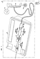
- Figure 1 shows a telephone set which includes a noise compensation system in accordance with an illustrative embodiment of the present invention.
- Figure 2 shows a system-level diagram of a broadband-based illustrative embodiment of a noise compensation system in accordance with the present invention.
- Figure 3 shows an illustrative implementation of the noise level estimation unit of the system of Figure 2.
- Figure 4 shows an illustrative implementation of the gain computation unit of the system of Figure 2.
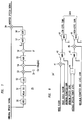
- Figure 5 is a graph which shows a compressor gain which may be applied to the original speech signal by the signal boost unit of the system of Figure 2 applying compressed amplification.
- Figure 6 is a graph of the corresponding transfer function for the illustrative signal boost unit which results from applying the gain shown in Figure 5.
- Figure 7 shows an illustrative implementation of the signal boost unit of an embodiment of the system of Figure 2 applying a compressed amplification as shown in the graphs of Figures 5 and 6.
- Figure 8 shows an alternative illustrative implementation of the gain computation unit of Figure 2 for use in an embodiment applying compressed amplification in an alternative manner.
- Figure 9 shows a system-level diagram of a multiband-based illustrative embodiment of the present invention in which noise compensation is performed in individual subbands.
- the present invention improves the signal-to-noise ratio (SNR) of a far-end speaker's speech in the near-end listener's ear when the near-end listener is using a telephone in a noisy environment.
- the level of the noise in the ear of the near-end listener can be estimated from the signal levels picked up by the transmitter (microphone) in the near-end listener's handset.
- the original speech signal generated by the far-end speaker may be modified within the telephone by being amplified by a variable gain factor so as to provide a more intelligible signal to the listener.
- This modification may advantageously also be a function of the level of the original speech signal itself.
- the speech power level i.e. , a "long-term" average level of the original speech signal
- relatively quiet signals may be boosted (i.e. , amplified) by a larger gain factor than relatively loud signals.
- the modification of the speech signal may comprise either a linear amplification or a non-linear, (illustratively) compressed, amplification.
- Compressed amplification in particular, boosts loud portions of the original speech signal by a lesser amount (i.e. , with a smaller gain factor) than quiet portions.
- Simple linear amplification by contrast, boosts all signal levels by an equal amount.
- Figure 1 shows telephone set 20 which includes a noise compensation system embodying the principles of the present invention.
- telephone set 20 of Figure 1 comprises a deskset 18 and a handset 13h (having microphone 13m and loudspeaker 13s ). Included within deskset 18 is noise compensation system 14 .
- the cord which connects handset 13h to deskset 18 is shown as emanating from the right side of deskset 18 , even though such cords most commonly emanate from the left side of a deskset.
- Deskset 18 further includes ideal hybrid 19 and side tone adder 21 .
- Ideal hybrid 19 converts between standard two-wire and four-wire telephone lines. It is ideal in that it substantially isolates the incoming signal from the outgoing signal on its four-wire side. In this manner, there is essentially no side tone component to the original speech signal which emanates from the four-wire side of the hybrid.
- Side tone adder 21 combines the signal from microphone 13m with the incoming (far- end) speech signal before it is provided to loudspeaker 13s . In particular, a reduced level of the signal from microphone 13m is mixed with the speech signal. Thus, a side tone is provided to the loudspeaker.
- Ideal hybrids and side tone adders are conventional components which may be found, for example, in certain electronic telephone sets. Other conventional components of a telephone set which are not relevant to the present invention are not shown.
- Noise compensation system 14 receives a noise-indicative signal from microphone 13m which is representative of the background noise (as illustrated as emanating from loudspeaker 17 ) as well as any speech provided to microphone 13m by the telephone user. Noise compensation system 14 also receives the original speech signal from a far-end speaker (whose telephone and the network connection thereto are not shown). Noise compensation system 14 determines the level of background noise from the noise-indicative signal, and boosts the original speech signal by a gain factor based on the background noise level to produce a modified speech signal. The side tone is then added to the modified speech signal by side tone adder 21 , and the resultant signal is then provided to loudspeaker 13s in handset 13h .
- the original speech signal as provided to noise compensation system 14 is substantially free of the background noise, since the side tone has not yet been added to the original (far-end) speech signal.
- the far-end speech is boosted without any simultaneous boost of the background noise in the side tone.
- Figure 2 shows a system-level diagram of a broadband-based illustrative embodiment of noise compensation system 14 .
- Inputs to the system include the original speech signal and the noise-indicative signal, which may further include speech provided by the near-end listener.
- the system produces a modified speech signal for improved intelligibility as output. All of the signals described with reference to the illustrative embodiment present herein are presumed to be in digital form.
- noise level estimation 22 determines the "noise floor” and outputs a signal representing that value.
- this signal represents the noise level over a first predetermined period of time.
- this first predetermined period e.g. , 250 milliseconds or less
- the noise floor signal represents a short-term (e.g. , 250 milliseconds) minimum value of an "exponentionally mapped past average” signal, and can be generated using known techniques.
- An illustrative implementation of noise level estimation 22 is shown in Figure 3 and described below.
- Gain computation 24 produces a gain signal, GAIN, whose value is proportional to the noise floor signal and inversely proportional to an average speech power level signal.
- This gain signal represents a gain factor (i.e., a multiplicative factor) by which the original speech signal may be amplified.
- the average speech power level signal is generated by speech power estimation 23 , and represents the average level of the original speech signal over a second predetermined period of time. That is, the average speech power level measures the "energy level of the speech signal. Providing such a gain dependence on the far-end speech level allows relatively quiet calls to receive a sufficient boost for a given background noise level, while preventing loud calls from being over-boosted.
- the second predetermined period By setting the second predetermined period to a relatively long value (e.g ., one second), it can more readily be determined whether the current far-end speech comprises a loud or soft segment of the call.
- the average speech power level signal represents a long-term average level.
- Speech power estimation 23 may be implemented by conventional signal energy estimation techniques. An illustrative implementation of gain computation 24 is shown in Figure 4 and described below.
- signal boost 25 which produces the modified speech signal.
- signal boost 25 may comprise a conventional amplifier (i.e. , a multiplier).
- the original speech signal is amplified by a gain factor equal to the value of the gain signal, GAIN.
- signal boost 25 may comprise circuitry (or procedural code) which amplifies the original speech signal by a gain factor less than or equal to the value of the gain signal, wherein the gain factor further depends on the level of the original speech signal itself. That is, the gain signal, GAIN, represents the maximum gain which will be applied by the "compressor.”
- An illustrative implementation of signal boost 25 providing compression is shown in Figure 7 and described below.
- Figure 3 shows an illustrative implementation of noise level estimation 22 of the system of Figure 2.
- HPF high pass filter
- HPF 31 removes DC from the input signal. It may be conventionally implemented as a first order recursive digital filter having a cutoff frequency of, for example, 20 Hz, and may be based on a standard telephony sampling frequency of 8 kHz.
- Absolute value block (ABS) 32 computes the magnitude of the sample and is also of conventional design.
- Low pass filter (LPF) 33 computes the exponentially mapped past average (EMP). As described above, the exponentially mapped past average comprises an exponentially weighted average value of the noise level.
- Minimum sample latch (MIN) 34 stores the minimum value of EMP over the first predetermined time period (e.g. , 250 milliseconds).
- the output signal of latch 34 MEMP, therefore represents the short-term minimum of the exponentionally mapped past average, and thus represents the short-term minimum value of the averaged noise-indicative signal.
- This signal is subsequently used to represent the noise floor over which far-end speech should be boosted.
- maximum sample latch (MAX) 35 stores the maximum value of EMP over the same predetermined period.
- the output signal of latch 35 , PEMP therefore represents the short-term peak of the exponentionally mapped past average, and thus represents the short-term peak value of the averaged noise-indicative signal.
- Latches 34 and 35 may be implemented by conventional digital comparators, selectors and storage devices, with the storage devices reset at the start of each cycle of the predetermined time period.
- Speech detector and noise floor estimator 36 generates the noise floor signal output based on signals MEMP and PEMP. Specifically, it performs two functions. First, it is determined whether the noise-indicative signal presently includes only noise or whether it presently includes speech as well. This question may be resolved by conventional techniques, such as those used in the implementation of conventional speakerphones. For example, the quotient of PEMP (representing the short-term peak value of the noise-indicative signal) divided by MEMP (representing the short- term minimum value of the noise-indicative signal) may be compared with a predetermined threshold. The larger this quotient, the larger the variability in the level of the input signal. If the level of the input signal is sufficiently variable within the first predetermined time period, it is presumed that speech is present. (Note that the variation in signal level of speech typically exceeds that of background noise.)
- speech detector and noise floor estimator 36 sets the output noise floor signal to a value which represents the estimated level of the noise floor. If it is determined that speech is not present, the noise floor signal is set to MEMP, the short-term minimum value of the noise-indicative signal. Otherwise, the noise floor signal remains unchanged -- that is, the previous value is maintained. In this manner, when the presence of speech makes it difficult to determine the actual present level of background noise, it is presumed that the noise level has not changed since the previous period.
- the value of PEMP alone may be compared with a predetermined threshold (rather than using the quotient of PEMP divided by MEMP), since speech is generally of a significantly higher intensity than is background noise.
- speech detection may be bypassed altogether, on the assumption that the far-end speaker will not be speaking at the same time that the near-end listener is speaking. In other words, we may not care what the "noise floor" is determined to be during periods when the near-end listener is speaking.
- maximum sample latch 35 and speech detector and noise floor estimator 36 may be removed from noise level estimation 22 of Figure 3, and the output of minimum sample latch 34 (i.e. , signal MEMP) may be used directly as the noise floor signal output of noise level estimation 22 .
- Figure 4 shows an illustrative implementation of gain computation 24 of the system of Figure 2.
- the gain signal is generated based on the noise floor signal from noise level estimation 22 and on the average speech power level signal from speech power estimation 23 .
- the computed gain is advantageously proportional to the noise floor and inversely proportional to the average speech power level.
- the gain is never less than one ( i.e. , the original speech signal is never attenuated) nor is it ever more than a maximum specified value.
- amplifier 41 multiplies the noise floor by a noise scale factor.
- This noise scale factor is set to an appropriate value so that the output signal of amplifier 41 , which is representative of a gain factor, is of the appropriate magnitude.
- the noise scale factor acts as a "sensitivity" control -- a smaller scale factor will result in more gain being applied for a given level of background noise.
- the magnitude of this signal may be advantageously set to that gain factor which will boost the lowest far-end speech levels by an appropriate amount to overcome the noise level.
- the noise scale factor may illustratively be set to a fractional value between zero and one, such as 0.4.
- minimizer (MIN) 42 compares the gain factor output by amplifier 41 to a maximum permitted gain factor to ensure that the system does not attempt to apply an excessive gain factor to the original speech signal.
- the maximum permitted gain factor may illustratively be set to 5.6 ( i.e. , 15 dB).
- Maximizer (MAX) 43 then ensures that the resultant gain factor is in no case less the one, so that the original speech signal is never attenuated.
- Divider 44 and minimizer (MIN) 45 determine an additional multiplicative factor to be incorporated in the gain computation so that the resultant gain will be inversely proportional to the average speech power level as provided by speech power estimation 23 .
- Divider 44 computes the quotient of a minimum far-end speech level divided by the average speech power level for use as this additional multiplicative factor.
- the minimum speech level represents the minimum level which is to be considered actual far-end speech, as distinguished from mere background noise during a period of silence by the far-end speaker.
- the minimum speech level may illustratively be set to a value representing -30 dBm.
- Minimizer 45 then ensures that this multiplicative factor does not exceed one. In this manner, the gain factor is not increased as the far-end speech level goes below the minimum, so that far-end background noise is not over-boosted ( i.e. , not boosted more than the quietest speech).
- Amplifier 46 multiplies the gain factor generated by amplifier 41 (through minimizer 42 and maximizer 43 ) by the additional multiplicative factor from divider 44 (through minimizer 45 ). Finally, maximizer (MAX) 47 ensures that the final gain factor is not less than one, so that the original speech signal is never attenuated.
- GAIN the resultant gain factor
- the technique of compressed amplification results in the application of more gain to lower energy signals than to higher energy signals. This helps to compensate for the listener's reduced dynamic range of hearing and undue growth of loudness which results from the presence of surrounding noise. Since lower energy signals tend to be masked by noise more than higher energy signals, the higher energy signals require less amplification. Moreover, this compression avoids distorting the speech by avoiding over-amplification of the high energy signals. Thus, the speech intelligibility is increased without the unwanted side effect of over-amplifying those sounds which are already sufficiently loud.
- Figure 5 is a graph which shows a compressor gain which may be applied to the original speech signal by the signal boost unit of an illustrative embodiment of the system of Figure 2 applying compressed amplification.
- Figure 6 is a graph which shows the corresponding transfer function for the illustrative signal boost unit which results from applying the gain shown in Figure 5.
- the gain (in decibels, or dB) to be applied varies from GL, a predetermined "low-level” gain which is applied to the lowest energy signals, down through GH, a "high-level” gain, to no gain at all ( i.e. , 0 dB) at the highest energy signals.
- the low-level gain, GL may be based on the output of gain computation 24 , GAIN, as shown in Figure 4 and described above.
- GAIN reflects a maximum gain factor
- GL reflects a gain in decibels
- the compressor "breakpoint,” BK is an original speech signal level threshold below which the gain applied remains constant. That is, signals below BK receive a linear boost while only those above BK are in fact compressed. By keeping the gain applied constant below this threshold, very low level signals, which likely represent only background noise at the far end (rather than actual far-end speech), will not be excessively amplified ( i.e. , will not be boosted more than the lowest level speech signals), while low level speech signals will still receive sufficient boost.
- P represents a point at which a high-level gain, GH, may be defined. Both the compressor breakpoint BK and the point P may be advantageously chosen so that most of the dynamic range of the original speech signal falls between BK and P.
- the low-level gain GL will be applied to the lowest level speech signals, while the high-level gain, GH, will be applied to the highest level speech signals.
- BK may be set at the minimum level which represents actual speech (as opposed to far-end background noise).
- P for example, may be set at a speech level which is exceeded only 10% of the time.
- either BK or P may be chosen as indicated above, and then the other parameter may be set 30 dB higher or lower, respectively.
- Figure 7 shows an illustrative implementation of the signal boost unit of the embodiment of the system of Figure 2 applying a compressed amplification as shown in the graphs of Figures 5 and 6.
- the illustrative implementation comprises absolute value block (ABS) 50 , peak detector 51 , logarithm block (LOG) 52 , multiplier 53 , adder 54 , minimizer (MIN) 55 , adder 56 , maximizer (MAX) 57 , exponentiator (EXP) 58 and multiplier 59 .
- ABS absolute value block
- LOG logarithm block
- MIN minimizer
- MAX maximizer
- EXP exponentiator
- absolute value block 50 computes the magnitude of the sample.
- Peak detector 51 controls the attack and release times of the compressor.
- peak detector 51 may be advantageously designed so as to provide instantaneous attack but syllabic release.
- An instantaneous attack time enables the compressor gain to be reduced instantaneously if the input signal level suddenly rises. Therefore, sudden, loud noises are prevented from being over-amplified, thus avoiding causing pain or injury to the listener's ear.
- the compressor gain increases, however, at a rate dependent on the release time constant.
- the release time constant may be set, for example, to 16 milliseconds (or less) to respond to the fast energy changes associated with the phonemes of spoken language.
- Logarithm block 52 converts the output signal of peak detector 51 into the logarithmic domain by taking the logarithm of the digital sample.
- Multiplier 53 , adder 54 and minimizer 55 compute the relative reduction in gain which is to result from the compression. That is, the amount by which the resultant gain will be reduced from the low-level gain, GL, (which represents the maximum gain) is calculated by these components.
- multiplier 53 multiplies the signal by the amount (k-1), where k is the reciprocal of the "compression ratio.”
- Adder 54 then adds the (negative) amount -(k-1) log (bk) to the result from multiplier 53 , where bk is the compressor breakpoint ( i.e. , BK) expressed as an absolute level on a linear scale.
- Minimizer 55 limits the result of the above computation to a value less than or equal to zero so that the final resultant compressed gain will never exceed the low-level gain, GL.
- Adder 56 adds in the amount gl, which is the logarithm of the gain which is introduced by the compressor at all levels less than bk ( i.e. , the low-level gain).
- Maximizer 57 ensures that the final result (as computed in the logarithmic domain) remains greater than or equal to zero to ensure that the original speech signal is never attenuated.
- Exponentiator 58 converts the computed compressed gain back out of the logarithmic domain to produce the final gain factor ( i.e. , the compressed gain).
- multiplier 59 applies this (multiplicative) gain factor to the original speech signal to produce the modified speech signal.
- FIG 8 shows an alternative illustrative implementation of the gain computation unit of Figure 2 for applying compressed amplification in a different manner than that described above.
- the low-level gain, GL, of the compressor of signal boost 25 is varied only as a function of the background noise level (and not based on the average speech power level), while the high-level gain, GH, is varied as a function of the average speech power level. That is, the low-level gain is proportional (only) to the noise floor, and the high-level gain is inversely proportional (only) to the average speech power level.
- GAIN output
- the result of this alternative implementation is that the effect of varying the low-level gain becomes essentially orthogonal to the effect of varying the high-level gain.
- varying the low-level gain will affect the intelligibility of the speech but the loudness will be relatively unaffected if the high-level gain remains constant.
- varying the high-level gain will affect the loudness of the speech but the intelligibility will be relatively unaffected if the low-level gain remains constant.
- the low-level gain becomes an intelligibility "control” and the high-level gain becomes a loudness "control.”
- the illustrative implementation described herein increases the low-level gain as the background noise increases, while it increases the high-level gain as the far-end speech level decreases.
- amplifier 41 , minimizer (MIN) 42 and maximizer (MAX) 43 produce a gain factor proportional to the noise floor in an analogous manner to the corresponding components of the implementation shown in Figure 4.
- the same parameters -- a noise scale factor and a maximum permitted gain factor -- are employed in the same manner.
- the resultant signal in this case, however, is the final low-level gain factor to be provided to the compressor of signal boost 25 .
- Divider 44 and minimizer (MIN) 45 determine an alternative gain factor (inversely proportional to the average speech power level), also in an analogous manner to the corresponding components of the implementation shown in Figure 4.
- Multiplier 48 then multiplies this factor (which is less than or equal to one) by a parameter representing the maximum permitted high-level gain factor to produce the high-level gain factor to be provided to the compressor of signal boost 25 .
- the maximum permitted high-level gain factor may advantageously be set to the low-level gain factor.
- Maximizer 49 like maximizer 43 , ensures that the resultant gain factor is at least one, so that the original speech signal is never attenuated.
- signal boost 25 may be implemented as shown in Figure 7 and described above.
- the compression ratio, CR may be readily computed as described above based on the low-level and high-level gain factors generated by gain computation 24' .
- the compressed gain may then be computed based on the values of k (1/CR), bk and gl (based in turn on the low-level gain factor) as described above.
- Figure 9 shows a system-level diagram of a multiband-based illustrative embodiment of the present invention in which noise compensation is performed in individual (frequency) subbands.
- noise compensation is performed in individual (frequency) subbands.
- the noise energy in one frequency band will not affect the gain applied to the original speech signal at other frequencies.
- high energy, low frequency components in the original speech signal will advantageously not affect the gain applied to the high frequency components of the signal.
- multiband-based noise compensation permits better adaptation to the spectral characteristics of the background noise.
- each of the processes performed by the broadband system of Figure 2 is performed by the multiband system of Figure 9 in a plurality of independent subbands.
- each of the four components shown in Figure 2 may be replaced by a plurality of corresponding "copies" of the given component, each of which operates on one of the n subbands into which each of the input signals is separated. Since subband-based processing of speech and audio signals is well known, the following description provides an overview of the multiband implementation of Figure 9.
- multiband noise compensation system 14' comprises analysis filter banks 61 and 62 , noise level estimation 22' , speech power estimation 23' , gain computation 24' , and signal boost 25' and adder 63 .
- Each of the two input signals -- the noise-indicative signal and the original speech signal -- are separated into a corresponding set of n subband signals by analysis filter banks 61 and 62 in a conventional manner.
- these two filter banks are identical so that the two signals are separated into corresponding sets of subband signals having exactly the same frequency band structure.
- Noise level estimation 22' comprises subband noise level estimation 22-1 ,. .. 22-n ; speech power estimation 23' comprises subband speech power estimation 23-1 ,... 23-n ; gain computation 24' comprises subband gain computation 24-1 ,. .. 24-n ; and signal boost 25' comprises subband signal boost 25-1 ,... 25-n .
- Each corresponding set of components 22-i , 23-i , 24-i and 25-i (corresponding to the i 'th subband) have a corresponding internal structure and operate in an analogous manner to components 22 , 23 , 24 and 25 of broadband noise compensation system 14 of Figure 2.
- speech power estimation is not performed in subbands.
- speech power estimation 23 of the broadband system of Figure 2 may be used in place of speech power estimation 23' , providing its output signal (average speech power level) to each of the subband gain computation components ( 24-1 ,... 24-n ). That is, this alternate embodiment provides gain factors in each subband which are inversely proportional to the overall speech power level of the original speech signal as a whole, rather than to the power level in each subband individually.
- the various parameters e.g. , the noise scale factor, the maximum permitted gain factor, the minimum speech level, etc.
- the various parameters e.g. , the noise scale factor, the maximum permitted gain factor, the minimum speech level, etc.
- the release time of peak detector 51 in a higher frequency band may be advantageously set lower than the release time for a corresponding peak detector in a lower frequency band.
- processors For clarity of explanation, the illustrative embodiment of the present invention is presented as comprising individual functional blocks. The functions these blocks represent may be provided through the use of either shared or dedicated hardware, including, but not limited to, hardware capable of executing software. For example, the functions of processors presented in the various figures may be provided by a single shared processor. (Use of the term "processor” should not be construed to refer exclusively to hardware capable of executing software.)
- Illustrative embodiments may comprise digital signal processor (DSP) hardware, read-only memory (ROM) for storing software performing the operations discussed below, and random access memory (RAM) for storing DSP results.
- DSP digital signal processor
- ROM read-only memory
- RAM random access memory
- VLSI Very large scale integration
Landscapes
- Engineering & Computer Science (AREA)
- Signal Processing (AREA)
- Tone Control, Compression And Expansion, Limiting Amplitude (AREA)
- Telephone Set Structure (AREA)
- Reduction Or Emphasis Of Bandwidth Of Signals (AREA)
- Telephone Function (AREA)
- Noise Elimination (AREA)
Applications Claiming Priority (2)
| Application Number | Priority Date | Filing Date | Title |
|---|---|---|---|
| US175038 | 1993-12-29 | ||
| US08/175,038 US5526419A (en) | 1993-12-29 | 1993-12-29 | Background noise compensation in a telephone set |
Publications (2)
| Publication Number | Publication Date |
|---|---|
| EP0661858A2 true EP0661858A2 (fr) | 1995-07-05 |
| EP0661858A3 EP0661858A3 (fr) | 1999-04-28 |
Family
ID=22638582
Family Applications (1)
| Application Number | Title | Priority Date | Filing Date |
|---|---|---|---|
| EP94309189A Ceased EP0661858A3 (fr) | 1993-12-29 | 1994-12-09 | Compensation du bruit de fond dans un poste téléphonique |
Country Status (5)
| Country | Link |
|---|---|
| US (2) | US5526419A (fr) |
| EP (1) | EP0661858A3 (fr) |
| JP (1) | JP4082745B2 (fr) |
| KR (1) | KR100323164B1 (fr) |
| CA (1) | CA2136365C (fr) |
Cited By (12)
| Publication number | Priority date | Publication date | Assignee | Title |
|---|---|---|---|---|
| DE19635878A1 (de) * | 1996-09-04 | 1998-03-05 | Deutsche Telekom Ag | Vorrichtung zur Verbesserung des Sendesignals einer Echoreduktionseinrichtung |
| US5734987A (en) * | 1994-04-26 | 1998-03-31 | Mitsubishi Denki Kabushiki Kaisha | Noise-controlled communication apparatus |
| EP0836310A1 (fr) * | 1996-10-10 | 1998-04-15 | Koninklijke Philips Electronics N.V. | Appareil telephonique muni de moyens de contrÔle automatique de gain |
| EP0717547A3 (fr) * | 1994-12-12 | 1998-05-27 | Nec Corporation | Circuit pour varier automatiquement le niveau d'un signal audio reçu dans un poste téléphonique |
| WO2000007344A1 (fr) * | 1998-07-29 | 2000-02-10 | Telefonaktiebolaget Lm Ericsson | Appareil telephonique avec reglage du volume |
| FR2783991A1 (fr) * | 1998-09-29 | 2000-03-31 | Philips Consumer Communication | Telephone avec moyens de rehaussement de l'impression subjective du signal en presence de bruit |
| WO2006125061A1 (fr) * | 2005-05-18 | 2006-11-23 | Bose Corporation | Reponse audiofrequence adaptee |
| WO2008134689A1 (fr) * | 2007-04-30 | 2008-11-06 | Qualcomm Incorporated | Ajustement de volume automatique et de portée dynamique pour des dispositifs audio mobiles |
| EP2066025A3 (fr) * | 2007-11-13 | 2010-03-17 | Sony Ericsson Mobile Communications Japan, Inc. | Appareil de traitement de signal audio, procédé de traitement de signal audio et terminal de communication |
| US8218783B2 (en) | 2008-12-23 | 2012-07-10 | Bose Corporation | Masking based gain control |
| US8229125B2 (en) | 2009-02-06 | 2012-07-24 | Bose Corporation | Adjusting dynamic range of an audio system |
| US8964997B2 (en) | 2005-05-18 | 2015-02-24 | Bose Corporation | Adapted audio masking |
Families Citing this family (45)
| Publication number | Priority date | Publication date | Assignee | Title |
|---|---|---|---|---|
| US5825671A (en) * | 1994-03-16 | 1998-10-20 | U.S. Philips Corporation | Signal-source characterization system |
| JPH0823373A (ja) * | 1994-07-08 | 1996-01-23 | Kokusai Electric Co Ltd | 通話器回路 |
| JP2606167B2 (ja) * | 1994-12-07 | 1997-04-30 | 日本電気株式会社 | 電話機 |
| FR2731123B1 (fr) * | 1995-02-27 | 1997-05-09 | Prescom Sarl | Correction de gain de haut-parleur pour un terminal telephonique mains-libres |
| JP3483695B2 (ja) * | 1996-03-14 | 2004-01-06 | 株式会社リコー | 音声通信装置 |
| US5892823A (en) | 1996-03-27 | 1999-04-06 | Hello Direct, Inc. | Smart interface technology |
| US6744882B1 (en) * | 1996-07-23 | 2004-06-01 | Qualcomm Inc. | Method and apparatus for automatically adjusting speaker and microphone gains within a mobile telephone |
| US6128370A (en) * | 1997-08-06 | 2000-10-03 | Lucent Technologies Inc. | Multiple tone detection using out-of-band background detector |
| US6505057B1 (en) | 1998-01-23 | 2003-01-07 | Digisonix Llc | Integrated vehicle voice enhancement system and hands-free cellular telephone system |
| US6807280B1 (en) * | 1998-01-26 | 2004-10-19 | Delphi Technologies, Inc. | Audio signal processing circuit for reducing noise in an audio signal |
| US6959176B1 (en) * | 1999-04-07 | 2005-10-25 | Siemens Aktiengesellschaft | Communications terminal |
| US6618701B2 (en) * | 1999-04-19 | 2003-09-09 | Motorola, Inc. | Method and system for noise suppression using external voice activity detection |
| EP1210765B1 (fr) | 1999-07-28 | 2007-03-07 | Clear Audio Ltd. | Regulation audio par banc de filtres dans un environnement bruyant |
| US6711259B1 (en) * | 1999-11-22 | 2004-03-23 | Lucent Technologies Inc | Method and apparatus for noise suppression and side-tone generation |
| US7558391B2 (en) * | 1999-11-29 | 2009-07-07 | Bizjak Karl L | Compander architecture and methods |
| US6366880B1 (en) * | 1999-11-30 | 2002-04-02 | Motorola, Inc. | Method and apparatus for suppressing acoustic background noise in a communication system by equaliztion of pre-and post-comb-filtered subband spectral energies |
| KR100343776B1 (ko) * | 1999-12-03 | 2002-07-20 | 한국전자통신연구원 | 디지털 전화 단말기에서 주변소음에 따른 신호음 및/또는수신음 크기 조절장치 및 방법 |
| ATE248497T1 (de) * | 1999-12-09 | 2003-09-15 | Frederick Johannes Bruwer | Sprachsverteilungssystem |
| US6760435B1 (en) | 2000-02-08 | 2004-07-06 | Lucent Technologies Inc. | Method and apparatus for network speech enhancement |
| US20040057586A1 (en) * | 2000-07-27 | 2004-03-25 | Zvi Licht | Voice enhancement system |
| JP2002152397A (ja) * | 2000-11-10 | 2002-05-24 | Honda Motor Co Ltd | 通話装置 |
| US6768795B2 (en) * | 2001-01-11 | 2004-07-27 | Telefonaktiebolaget Lm Ericsson (Publ) | Side-tone control within a telecommunication instrument |
| US6785382B2 (en) | 2001-02-12 | 2004-08-31 | Signalworks, Inc. | System and method for controlling a filter to enhance speakerphone performance |
| US20020172350A1 (en) * | 2001-05-15 | 2002-11-21 | Edwards Brent W. | Method for generating a final signal from a near-end signal and a far-end signal |
| US7274794B1 (en) | 2001-08-10 | 2007-09-25 | Sonic Innovations, Inc. | Sound processing system including forward filter that exhibits arbitrary directivity and gradient response in single wave sound environment |
| US6944474B2 (en) | 2001-09-20 | 2005-09-13 | Sound Id | Sound enhancement for mobile phones and other products producing personalized audio for users |
| US7010118B2 (en) | 2001-09-21 | 2006-03-07 | Agere Systems, Inc. | Noise compensation methods and systems for increasing the clarity of voice communications |
| US20030182000A1 (en) * | 2002-03-22 | 2003-09-25 | Sound Id | Alternative sound track for hearing-handicapped users and stressful environments |
| US20030223597A1 (en) * | 2002-05-29 | 2003-12-04 | Sunil Puria | Adapative noise compensation for dynamic signal enhancement |
| US7242763B2 (en) * | 2002-11-26 | 2007-07-10 | Lucent Technologies Inc. | Systems and methods for far-end noise reduction and near-end noise compensation in a mixed time-frequency domain compander to improve signal quality in communications systems |
| US7539614B2 (en) * | 2003-11-14 | 2009-05-26 | Nxp B.V. | System and method for audio signal processing using different gain factors for voiced and unvoiced phonemes |
| US8311230B2 (en) * | 2004-02-27 | 2012-11-13 | Thomson Licensing | Speaker systems and methods having amplitude and frequency response compensation |
| US9008319B2 (en) * | 2004-12-30 | 2015-04-14 | Plantronics, Inc. | Sound pressure level limiter with anti-startle feature |
| US20070032259A1 (en) * | 2005-08-05 | 2007-02-08 | George Gounaris | Method and apparatus for voice amplitude feedback in a communications device |
| US8849231B1 (en) * | 2007-08-08 | 2014-09-30 | Audience, Inc. | System and method for adaptive power control |
| DE102006032543A1 (de) * | 2006-07-13 | 2008-01-17 | Nokia Siemens Networks Gmbh & Co.Kg | Verfahren und System zur Reduzierung des Empfangs unerwünschter Nachrichten |
| JP2008197200A (ja) * | 2007-02-09 | 2008-08-28 | Ari Associates:Kk | 了解度自動調整装置及び了解度自動調整方法 |
| KR101361052B1 (ko) * | 2007-02-14 | 2014-02-10 | 삼성전자주식회사 | 휴대용 오디오 장치의 오디오 신호 출력 레벨 제어 방법 및그 장치 |
| US8831936B2 (en) * | 2008-05-29 | 2014-09-09 | Qualcomm Incorporated | Systems, methods, apparatus, and computer program products for speech signal processing using spectral contrast enhancement |
| US8538749B2 (en) | 2008-07-18 | 2013-09-17 | Qualcomm Incorporated | Systems, methods, apparatus, and computer program products for enhanced intelligibility |
| US9202456B2 (en) * | 2009-04-23 | 2015-12-01 | Qualcomm Incorporated | Systems, methods, apparatus, and computer-readable media for automatic control of active noise cancellation |
| US9053697B2 (en) | 2010-06-01 | 2015-06-09 | Qualcomm Incorporated | Systems, methods, devices, apparatus, and computer program products for audio equalization |
| US8965774B2 (en) * | 2011-08-23 | 2015-02-24 | Apple Inc. | Automatic detection of audio compression parameters |
| US8639294B2 (en) | 2012-05-01 | 2014-01-28 | Audyssey Laboratories, Inc. | System and method for performing automatic gain control in mobile phone environments |
| WO2020020043A1 (fr) * | 2018-07-25 | 2020-01-30 | Dolby Laboratories Licensing Corporation | Courbe cible de compresseur pour éviter un bruit d'amplification |
Family Cites Families (27)
| Publication number | Priority date | Publication date | Assignee | Title |
|---|---|---|---|---|
| US3963868A (en) * | 1974-06-27 | 1976-06-15 | Stromberg-Carlson Corporation | Loudspeaking telephone hysteresis and ambient noise control |
| US4048443A (en) * | 1975-12-12 | 1977-09-13 | Bell Telephone Laboratories, Incorporated | Digital speech communication system for minimizing quantizing noise |
| US4076968A (en) * | 1976-09-02 | 1978-02-28 | Bell Telephone Laboratories, Incorporated | Telephone ringer intensity control responsive to ambient noise |
| GB2029141A (en) * | 1978-08-26 | 1980-03-12 | Viva Co | Gain control arrangements |
| DE3426068A1 (de) * | 1983-09-22 | 1985-04-11 | Blaupunkt-Werke Gmbh, 3200 Hildesheim | Verfahren zum anpassen der lautstaerke eines lautsprechers an einen am lautsprecherort herrschenden stoergeraeuschpegel |
| JPS60148259A (ja) * | 1984-01-13 | 1985-08-05 | Nippo Tsushin Kogyo Kk | 側音減衰量自動調整機能を備えた電話機 |
| US4604501A (en) * | 1984-10-09 | 1986-08-05 | Moscow K. Richmond | Voice communication system |
| CA1233925A (fr) * | 1985-05-10 | 1988-03-08 | Gordon J. Reesor | Telephone numerique a haut-parleur |
| US4630305A (en) * | 1985-07-01 | 1986-12-16 | Motorola, Inc. | Automatic gain selector for a noise suppression system |
| US4715063A (en) * | 1985-08-20 | 1987-12-22 | Motorola, Inc. | Speakerphone for radio and landline telephones |
| EP0290952B1 (fr) * | 1987-05-15 | 1992-11-04 | Alcatel SEL Aktiengesellschaft | Montage pour commande de la parole pour un terminal de télécommunication |
| CA1291837C (fr) * | 1987-07-15 | 1991-11-05 | Juro Ohga | Poste telephonique a suppression du bruit |
| US4811404A (en) * | 1987-10-01 | 1989-03-07 | Motorola, Inc. | Noise suppression system |
| US4829565A (en) * | 1987-10-20 | 1989-05-09 | Goldberg Robert M | Telephone with background volume control |
| US4847897A (en) * | 1987-12-11 | 1989-07-11 | American Telephone And Telegraph Company | Adaptive expander for telephones |
| US4882762A (en) * | 1988-02-23 | 1989-11-21 | Resound Corporation | Multi-band programmable compression system |
| DE3808038A1 (de) * | 1988-03-10 | 1989-09-28 | Siemens Ag | Verfahren zur automatischen anpassung eines spracherkennungssystems |
| FI80173C (fi) * | 1988-05-26 | 1990-04-10 | Nokia Mobile Phones Ltd | Foerfarande foer daempning av stoerningar. |
| US5138664A (en) * | 1989-03-25 | 1992-08-11 | Sony Corporation | Noise reducing device |
| US5001763A (en) * | 1989-08-10 | 1991-03-19 | Mnc Inc. | Electroacoustic device for hearing needs including noise cancellation |
| US5117461A (en) * | 1989-08-10 | 1992-05-26 | Mnc, Inc. | Electroacoustic device for hearing needs including noise cancellation |
| US5134659A (en) * | 1990-07-10 | 1992-07-28 | Mnc, Inc. | Method and apparatus for performing noise cancelling and headphoning |
| US5138663A (en) * | 1989-08-10 | 1992-08-11 | Mnc, Inc. | Method and apparatus for performing noise cancelling and headphoning |
| GB2239971B (en) * | 1989-12-06 | 1993-09-29 | Ca Nat Research Council | System for separating speech from background noise |
| US5239578A (en) * | 1990-05-15 | 1993-08-24 | Plantronics, Inc. | Noise cancelling apparatus for a telephone handset |
| US5170430A (en) * | 1991-01-04 | 1992-12-08 | Schuh Peter O | Voice-switched handset receive amplifier |
| US5353376A (en) * | 1992-03-20 | 1994-10-04 | Texas Instruments Incorporated | System and method for improved speech acquisition for hands-free voice telecommunication in a noisy environment |
-
1993
- 1993-12-29 US US08/175,038 patent/US5526419A/en not_active Expired - Lifetime
-
1994
- 1994-11-22 CA CA002136365A patent/CA2136365C/fr not_active Expired - Lifetime
- 1994-12-09 EP EP94309189A patent/EP0661858A3/fr not_active Ceased
- 1994-12-27 KR KR1019940037385A patent/KR100323164B1/ko not_active Expired - Lifetime
- 1994-12-27 JP JP32436894A patent/JP4082745B2/ja not_active Expired - Lifetime
-
1995
- 1995-05-18 US US08/443,512 patent/US5553134A/en not_active Expired - Lifetime
Cited By (22)
| Publication number | Priority date | Publication date | Assignee | Title |
|---|---|---|---|---|
| US5734987A (en) * | 1994-04-26 | 1998-03-31 | Mitsubishi Denki Kabushiki Kaisha | Noise-controlled communication apparatus |
| GB2288959B (en) * | 1994-04-26 | 1999-03-31 | Mitsubishi Electric Corp | A noise-controlled communication apparatus |
| EP0717547A3 (fr) * | 1994-12-12 | 1998-05-27 | Nec Corporation | Circuit pour varier automatiquement le niveau d'un signal audio reçu dans un poste téléphonique |
| US5896450A (en) * | 1994-12-12 | 1999-04-20 | Nec Corporation | Automatically variable circuit of sound level of received voice signal in telephone |
| DE19635878A1 (de) * | 1996-09-04 | 1998-03-05 | Deutsche Telekom Ag | Vorrichtung zur Verbesserung des Sendesignals einer Echoreduktionseinrichtung |
| EP0836310A1 (fr) * | 1996-10-10 | 1998-04-15 | Koninklijke Philips Electronics N.V. | Appareil telephonique muni de moyens de contrÔle automatique de gain |
| FR2754663A1 (fr) * | 1996-10-10 | 1998-04-17 | Philips Electronics Nv | Appareil telephonique muni de moyens de controle automatique de gain |
| AU755132B2 (en) * | 1998-07-29 | 2002-12-05 | Telefonaktiebolaget Lm Ericsson (Publ) | Telephone apparatus with volume control |
| WO2000007344A1 (fr) * | 1998-07-29 | 2000-02-10 | Telefonaktiebolaget Lm Ericsson | Appareil telephonique avec reglage du volume |
| US6834107B1 (en) | 1998-07-29 | 2004-12-21 | Telefonaktiebolaget Lm Ericsson | Telephone apparatus |
| KR100760728B1 (ko) * | 1998-07-29 | 2007-09-21 | 텔레폰악티에볼라겟 엘엠 에릭슨(펍) | 전화기 |
| WO2000019686A1 (fr) * | 1998-09-29 | 2000-04-06 | Koninklijke Philips Electronics N.V. | Telephone avec dispositif permettant d'ameliorer l'impression de signal subjective en presence de bruit |
| FR2783991A1 (fr) * | 1998-09-29 | 2000-03-31 | Philips Consumer Communication | Telephone avec moyens de rehaussement de l'impression subjective du signal en presence de bruit |
| CN101208742B (zh) * | 2005-05-18 | 2013-01-02 | 伯斯有限公司 | 自适应的音频响应 |
| WO2006125061A1 (fr) * | 2005-05-18 | 2006-11-23 | Bose Corporation | Reponse audiofrequence adaptee |
| US8964997B2 (en) | 2005-05-18 | 2015-02-24 | Bose Corporation | Adapted audio masking |
| WO2008134689A1 (fr) * | 2007-04-30 | 2008-11-06 | Qualcomm Incorporated | Ajustement de volume automatique et de portée dynamique pour des dispositifs audio mobiles |
| US7742746B2 (en) | 2007-04-30 | 2010-06-22 | Qualcomm Incorporated | Automatic volume and dynamic range adjustment for mobile audio devices |
| US8364478B2 (en) | 2007-11-13 | 2013-01-29 | Sony Mobile Communicatins Japan, Inc. | Audio signal processing apparatus, audio signal processing method, and communication terminal |
| EP2066025A3 (fr) * | 2007-11-13 | 2010-03-17 | Sony Ericsson Mobile Communications Japan, Inc. | Appareil de traitement de signal audio, procédé de traitement de signal audio et terminal de communication |
| US8218783B2 (en) | 2008-12-23 | 2012-07-10 | Bose Corporation | Masking based gain control |
| US8229125B2 (en) | 2009-02-06 | 2012-07-24 | Bose Corporation | Adjusting dynamic range of an audio system |
Also Published As
| Publication number | Publication date |
|---|---|
| JP4082745B2 (ja) | 2008-04-30 |
| KR950022572A (ko) | 1995-07-28 |
| KR100323164B1 (ko) | 2002-06-20 |
| US5553134A (en) | 1996-09-03 |
| CA2136365A1 (fr) | 1995-06-30 |
| US5526419A (en) | 1996-06-11 |
| CA2136365C (fr) | 1999-04-20 |
| JPH07212435A (ja) | 1995-08-11 |
| EP0661858A3 (fr) | 1999-04-28 |
Similar Documents
| Publication | Publication Date | Title |
|---|---|---|
| US5526419A (en) | Background noise compensation in a telephone set | |
| US5524148A (en) | Background noise compensation in a telephone network | |
| US6904146B2 (en) | Full duplex echo cancelling circuit | |
| US7630887B2 (en) | Enhancing the intelligibility of received speech in a noisy environment | |
| US5365583A (en) | Method for fail-safe operation in a speaker phone system | |
| EP0763888B1 (fr) | Procédé et circuit pour le traitement de signaux audio | |
| EP1599992B1 (fr) | Amelioration de l'audibilite | |
| US9699554B1 (en) | Adaptive signal equalization | |
| US20020172350A1 (en) | Method for generating a final signal from a near-end signal and a far-end signal | |
| JPS63314943A (ja) | ボリュームレンジ制御回路 | |
| US6799062B1 (en) | Full-duplex hands-free transparency circuit and method therefor | |
| US6798881B2 (en) | Noise reduction circuit for telephones | |
| JP3342642B2 (ja) | 電話送受器インタフェース装置 | |
| KR20020011131A (ko) | 이동전화 스피커와 마이크로폰 이득을 자동으로 조정하는방법 및 장치 | |
| US5586180A (en) | Method of automatic speech direction reversal and circuit configuration for implementing the method | |
| US20020012429A1 (en) | Interference-signal-dependent adaptive echo suppression | |
| EP4362015A1 (fr) | Amélioration de l'intelligibilité de la parole à l'extrémité proche avec des artéfacts minimaux | |
| US20050213745A1 (en) | Voice activity detector for low S/N | |
| HK1086412B (en) | Audibility enhancement |
Legal Events
| Date | Code | Title | Description |
|---|---|---|---|
| PUAI | Public reference made under article 153(3) epc to a published international application that has entered the european phase |
Free format text: ORIGINAL CODE: 0009012 |
|
| AK | Designated contracting states |
Kind code of ref document: A2 Designated state(s): DE FR GB IT |
|
| PUAL | Search report despatched |
Free format text: ORIGINAL CODE: 0009013 |
|
| AK | Designated contracting states |
Kind code of ref document: A3 Designated state(s): DE FR GB IT |
|
| 17P | Request for examination filed |
Effective date: 19991013 |
|
| 17Q | First examination report despatched |
Effective date: 20010201 |
|
| STAA | Information on the status of an ep patent application or granted ep patent |
Free format text: STATUS: THE APPLICATION HAS BEEN REFUSED |
|
| 18R | Application refused |
Effective date: 20040220 |