EP0662047B1 - Vorrichtung zur variablen einstellung des neigungswinkels eines tastaturgehäuses - Google Patents
Vorrichtung zur variablen einstellung des neigungswinkels eines tastaturgehäuses Download PDFInfo
- Publication number
- EP0662047B1 EP0662047B1 EP93919008A EP93919008A EP0662047B1 EP 0662047 B1 EP0662047 B1 EP 0662047B1 EP 93919008 A EP93919008 A EP 93919008A EP 93919008 A EP93919008 A EP 93919008A EP 0662047 B1 EP0662047 B1 EP 0662047B1
- Authority
- EP
- European Patent Office
- Prior art keywords
- bearing element
- brackets
- bearing
- locking
- running
- Prior art date
- Legal status (The legal status is an assumption and is not a legal conclusion. Google has not performed a legal analysis and makes no representation as to the accuracy of the status listed.)
- Expired - Lifetime
Links
Images
Classifications
-
- B—PERFORMING OPERATIONS; TRANSPORTING
- B41—PRINTING; LINING MACHINES; TYPEWRITERS; STAMPS
- B41J—TYPEWRITERS; SELECTIVE PRINTING MECHANISMS, i.e. MECHANISMS PRINTING OTHERWISE THAN FROM A FORME; CORRECTION OF TYPOGRAPHICAL ERRORS
- B41J5/00—Devices or arrangements for controlling character selection
- B41J5/08—Character or syllable selected by means of keys or keyboards of the typewriter type
- B41J5/10—Arrangements of keyboards, e.g. key button disposition
-
- G—PHYSICS
- G06—COMPUTING OR CALCULATING; COUNTING
- G06F—ELECTRIC DIGITAL DATA PROCESSING
- G06F3/00—Input arrangements for transferring data to be processed into a form capable of being handled by the computer; Output arrangements for transferring data from processing unit to output unit, e.g. interface arrangements
- G06F3/01—Input arrangements or combined input and output arrangements for interaction between user and computer
- G06F3/02—Input arrangements using manually operated switches, e.g. using keyboards or dials
- G06F3/0202—Constructional details or processes of manufacture of the input device
- G06F3/0208—Arrangements for adjusting the tilt angle of a keyboard, e.g. pivoting legs
-
- B—PERFORMING OPERATIONS; TRANSPORTING
- B41—PRINTING; LINING MACHINES; TYPEWRITERS; STAMPS
- B41J—TYPEWRITERS; SELECTIVE PRINTING MECHANISMS, i.e. MECHANISMS PRINTING OTHERWISE THAN FROM A FORME; CORRECTION OF TYPOGRAPHICAL ERRORS
- B41J5/00—Devices or arrangements for controlling character selection
- B41J5/08—Character or syllable selected by means of keys or keyboards of the typewriter type
- B41J5/10—Arrangements of keyboards, e.g. key button disposition
- B41J5/105—Constructional details of keyboard frames, e.g. adjusting or fixation means
-
- H—ELECTRICITY
- H01—ELECTRIC ELEMENTS
- H01H—ELECTRIC SWITCHES; RELAYS; SELECTORS; EMERGENCY PROTECTIVE DEVICES
- H01H2217/00—Facilitation of operation; Human engineering
- H01H2217/028—Facilitation of operation; Human engineering on planes with different or alterable inclination, e.g. convex plane
Definitions
- the invention relates to a device according to the features of the preamble of claim 1.
- keyboards for operating devices have to meet ergonomic requirements aimed at ease of use, especially if, as with data processing systems, keyboards have to be operated for extended periods of time.
- the ergonomically offered designs of keyboards include the adjustability of the keyboard inclination in relation to a horizontally running work surface, and the physical condition of different operators and the dimensions of different locations for the keyboards in an appropriate manner.
- the present invention is based on the object of designing a device for adjusting the inclination angle of keyboard housings in such a way that structural interventions in the shape of the housing are not necessary.
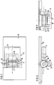
- the device shown in FIGS. 1 to 3 for adjusting the angle of inclination of a keyboard housing consists of two parts, a bearing element 1 and a base 2 which is pivotably attached to the bearing element 1.
- the bearing element 1 consists of a tubular body, on each of its two open ends a bearing journal 3, 4 of the base 2 is immersed and guided.
- the tubular bearing element 1 is arranged on the bottom surface of the keyboard housing lower part 5 and optionally embedded in a flat, circular-arc-shaped groove.
- the base 2, which is pivotally attached by means of the two bearing pins 3, 4, consists of two U-brackets 6, 7 of different lengths arranged in an L-shape.
- the part connecting the two U-legs is designed as a web running perpendicular to the U-legs, on the respective outer edge of which the base is supported, depending on the setting, on one of the two U-bars of different lengths in two different angles of inclination.
- the longer of the two U-brackets 7 has a tongue 8 clamped on one side on the web and running parallel to the U-legs, the free end of which engages in the bearing element 1 in a latching manner.
- the free tongue end which conforms as a circular arc segment to the lateral surface of the bearing element 1, has a latching element 9 in on the surface facing the bearing element 1 the shape of a wedge-shaped crosspiece, which, depending on the position of the base 2, engages in one of two locking notches 10, 11 offset from one another by 90 °.
- run-up bevels 12, 13 are provided at the two ends of the tubular bearing element 1, along which the journal 3, 4 of the pedestal 2 slide along during assembly, with the U-bracket 7 being slightly spread apart and ultimately dip into the two pipe ends.
Landscapes
- Engineering & Computer Science (AREA)
- General Engineering & Computer Science (AREA)
- Theoretical Computer Science (AREA)
- Human Computer Interaction (AREA)
- Physics & Mathematics (AREA)
- General Physics & Mathematics (AREA)
- Input From Keyboards Or The Like (AREA)
- Record Information Processing For Printing (AREA)
- Pivots And Pivotal Connections (AREA)
- Electrophonic Musical Instruments (AREA)
- Switches With Compound Operations (AREA)
Abstract
Description
- Die Erfindung betrifft eine Vorrichtung nach den Merkmalen des Oberbegriffs des Anspruchs 1.
- Tastaturen zur Bedienung von Geräten haben auf den Bedienungskomfort gerichtete ergonomische Anforderungen zu erfüllen, insbesondere wenn, wie bei Datenverarbeitungsanlagen, Tastaturen über längere Zeiträume zu betätigen sind. Zu den ergonomisch gebotenen Ausgestaltungen von Tasturen gehört die Verstellbarkeit der Tastaturneigung gegenüber einer horizontal verlaufenden Arbeitsfläche, und der körperlichen Beschaffenheit unterschiedlicher Bedienpersonen und den Abmessungen unterschiedlicher Einsatzorte für die Tastaruren in angemessener Weise gerecht zu werden.
- Vorrichtungen zur Neigungswinkeleinstellung von Tastaturgehäusen sind beispielsweise aus EP B 0 216 274 und "IBM Technical Disclosure Bulletin, Vol. 26, No. 7A, Dezember 1983, Seiten 3277 - 3278 bekannt. In beiden Vorrichtungen sind die für die Befestigung der ausschwenkbaren Standfüße vorgesehenen Lagerelemente relativ aufwendig gestaltet, so daß für das die Lagerelemente aufnehmende Tastaturgehäuse ein erheblicher konstruktiver und fertigungstechnischer Mehraufwand erforderlich ist.
- Der vorliegenden Erfindung liegt nun die Aufgabe zugrunde, eine Vorrichtung zur Einstellung des Nueigungswinkels von Tastaturgehäusen so zu gestalten, daß konstruktive Eingriffe in die Form des Gehäuses nicht erforderlich sind.
- Die Lösung dieser Aufgabe ergibt sich erfindungsgemäß durch die Merkmale des Anspruchs 1. Vorteilhafte Weiterbildungen der Erfindung sind in den Unteransprüchen angegeben.
- Ein Ausführungsbeispiel der Erfindung wird im folgenden anhand der Zeichnung näher erläutert. Dabei zeigen:
- Figur 1, 2, 3, eine erfindungsgemäße Vorrichtung in Drauf-, Seiten- und Vorderansicht.
- Die in Figuren 1 bis 3 dargestellte Vorrichtung zur Neigungswinkeleinstellung eines Tastaturgehäuses besteht aus zwei Teilen, einem Lagerelement 1 und einem am Lagerelement 1 schwenkbar befestigten Standfuß 2. Das Lagerelement 1 besteht aus einem rohrförmigen Körper, an dessen beiden offenen Enden je ein Lagerzapfen 3, 4 des Standfußes 2 eintaucht und geführt ist. Das rohrförmige Lagerelement 1 ist an der Bodenfläche des Tastaturgehäuseunterteils 5 angeordnet und gegebenenfalls in einer flachen kreisbogenförmig geformten Rille eingebettet. Der mittels der beiden Lagerzapfen 3, 4 schwenkbar befestigte Standfuß 2 besteht aus zwei in L-Form angeordneten U-Bügeln 6, 7 unterschiedlicher Länge. Der jeweils die beiden U-Schenkel verbindende Teil ist als senkrecht zu den U-Schenkeln verlaufender Steg ausgebildet, an dessen jeweiliger Außenkante sich der Standfuß je nach Einstellung auf einen der beiden unterschiedlich langen U-Bügel in zwei verschiedenen Neigungswinkelstellungen abstützt.
- Vorzugsweise der längere der beiden U-Bügel 7 weist eine am Steg einseitig eingespannte und parallel zu den U-Schenkeln verlaufende Zunge 8 auf, deren freies Ende rastend in das Lagerelement 1 eingreift. Zu diesem Zweck weist das freie Zungenende, das sich als Kreisbogensegment an die Mantelfläche des Lagerelements 1 anschmiegt, an der dem Lagerelement 1 zugewandten Fläche ein Rastelement 9 in der Form eines keilförmigen Quersteges auf, das je nach Stellung des Standfußes 2 in eine von zwei um 90° Grad gegeneinander versetzte Rastkerben 10, 11 eingreift. Zur erleichterten Montage des Standfußes 2 am Lagerelement 1 sind an den beiden Enden des rohrförmigen Lagerelements 1 quer zur Rohrachse verlaufende Auflaufschrägen 12, 13 vorgesehen, an denen die Lagerzapfen 3, 4 des Standfußes 2 bei der Montage unter leichter Aufspreizung des U-Bügels 7 entlanggleiten und letztlich in die beiden Rohrenden eintauchen.
Claims (6)
- Vorrichtung zur variablen Einstellung des Neigungswinkels eines auf einer ebenen Stellfläche aufliegenden rechteckigen Tastaturgehäuses unter Verwendung von im Bereich der beiden hinteren Gehäuseecken schwenkbar gelagerten Standfüssen, die in wenigstens zwei verschiedenen Neigungswinkelstellungen fixierbar sind,
dadurch gekennzeichnet,
daß am Gehäuseboden ein rohrförmiges, an beiden Enden offenes Lagerelement (1) befestigt ist, daß an diesem Lagerelement (1) ein an beiden Rohrenden mittels je eines Lagerzapfens (3, 4) geführter Standfuß (2) befestigt ist, der aus zwei in L-Form angeordneten, jeweils von den Lagerzapfen abstehenden U-Bügeln (6, 7) unterschiedlicher Länge besteht und daß an wenigstens einem der beiden U-Bügel (7) ein in das Lagerelement (1) eingreifendes Rastelement vorgesehen ist. - Vorrichtung nach Anspruch 1,
dadurch gekennzeichnet,
daß der jeweils die beiden U-Schenkel verbindende Teil der beiden U-Bügel (6, 7) als streifenförmiger, rechtwinklig zu den U-Schenkeln verlaufender Steg ausgebildet ist. - Vorrichtung nach Anspruch 1 oder 2,
dadurch gekennzeichnet,
daß bei wenigstens einem der beiden U-Bügel (6, 7) eine parallel zu den U-Schenkeln verlaufende, einseitig am U-Bügel eingespannte Zunge (8) verläuft, deren freies Ende rastend in das Lagerelement (1) eingreift. - Vorrichtung nach Anspruch 3,
dadurch gekennzeichnet,
daß an der Außenfläche des rohrförmigen Lagerelements wenigstens zwei jeweils parallel zur Rohrachse verlaufende nutartige Rastkerben (10, 11) vorgesehen sind. - Vorrichtung nach Anspruch 3 oder 4,
dadurch gekennzeichnet,
daß das freie Ende-der Zunge (8) eine der Außenfläche des Lagerelements angepaßte kreisbogensegmentförmige Gestalt aufweist und daß das in die Rastkerben (10, 11) des Lagerelements (1) eingreifende Rastelement (9) an der Innenfläche des Kreisbogensegments angeordnet ist. - Vorrichtung nach einem der vorhergehenden Ansprüche,
dadurch gekennzeichnet,
daß an den beiden Enden des rohrförmigen Lagerelements (1) quer zur Rohrachse verlaufende Auflaufschrägen (12, 13) vorgesehen sind, an denen die Lagerzapfen (3, 4) des Standfußes (2) bei der Montage unter leichter Aufspreizung der U-Bügel (6, 7) entlanggleiten und letztlich in die beiden Rohrenden eintauchen.
Applications Claiming Priority (3)
| Application Number | Priority Date | Filing Date | Title |
|---|---|---|---|
| DE4232483 | 1992-09-28 | ||
| DE4232483 | 1992-09-28 | ||
| PCT/DE1993/000872 WO1994007701A1 (de) | 1992-09-28 | 1993-09-16 | Vorrichtung zur variablen einstellung des neigungswinkels eines tastaturgehäuses |
Publications (2)
| Publication Number | Publication Date |
|---|---|
| EP0662047A1 EP0662047A1 (de) | 1995-07-12 |
| EP0662047B1 true EP0662047B1 (de) | 1997-01-02 |
Family
ID=6469035
Family Applications (1)
| Application Number | Title | Priority Date | Filing Date |
|---|---|---|---|
| EP93919008A Expired - Lifetime EP0662047B1 (de) | 1992-09-28 | 1993-09-16 | Vorrichtung zur variablen einstellung des neigungswinkels eines tastaturgehäuses |
Country Status (8)
| Country | Link |
|---|---|
| US (1) | US5546271A (de) |
| EP (1) | EP0662047B1 (de) |
| JP (1) | JP2755824B2 (de) |
| KR (1) | KR100229959B1 (de) |
| DE (2) | DE9218453U1 (de) |
| ES (1) | ES2096322T3 (de) |
| TW (1) | TW371487U (de) |
| WO (1) | WO1994007701A1 (de) |
Families Citing this family (47)
| Publication number | Priority date | Publication date | Assignee | Title |
|---|---|---|---|---|
| US6296408B1 (en) * | 1993-08-05 | 2001-10-02 | Stephen F. Larkin | Programmed motion work station |
| JP2001290577A (ja) | 2000-04-06 | 2001-10-19 | Alps Electric Co Ltd | キーボード装置 |
| US6279861B1 (en) | 2000-09-08 | 2001-08-28 | William B. Nolan | Elevator clips for portable computer |
| JP2003141811A (ja) * | 2001-11-01 | 2003-05-16 | Matsushita Electric Ind Co Ltd | 光ディスク記録再生装置 |
| US6880796B2 (en) * | 2003-09-16 | 2005-04-19 | Inventec Multimedia & Telecom Corporation | Angle adjustment structure for electronic apparatus having display unit |
| US7113393B2 (en) * | 2003-11-18 | 2006-09-26 | 3M Innovative Properties Company | Adjustable keyboard support assembly |
| US6938866B2 (en) * | 2003-11-18 | 2005-09-06 | 3M Innovative Properties Company | Adjustable keyboard support assembly method of use |
| GB2420968A (en) * | 2004-12-10 | 2006-06-14 | David Charles Hamilton | Adjustable Keyboard supports |
| US20060291946A1 (en) * | 2005-06-24 | 2006-12-28 | Microsoft Corporation | Ergonomic apparatus for keyboard |
| JP5184977B2 (ja) * | 2008-06-05 | 2013-04-17 | パナソニック株式会社 | 携帯機器 |
| US9354748B2 (en) | 2012-02-13 | 2016-05-31 | Microsoft Technology Licensing, Llc | Optical stylus interaction |
| US9426905B2 (en) | 2012-03-02 | 2016-08-23 | Microsoft Technology Licensing, Llc | Connection device for computing devices |
| US8873227B2 (en) | 2012-03-02 | 2014-10-28 | Microsoft Corporation | Flexible hinge support layer |
| US8935774B2 (en) | 2012-03-02 | 2015-01-13 | Microsoft Corporation | Accessory device authentication |
| US9870066B2 (en) | 2012-03-02 | 2018-01-16 | Microsoft Technology Licensing, Llc | Method of manufacturing an input device |
| US9360893B2 (en) | 2012-03-02 | 2016-06-07 | Microsoft Technology Licensing, Llc | Input device writing surface |
| US9075566B2 (en) | 2012-03-02 | 2015-07-07 | Microsoft Technoogy Licensing, LLC | Flexible hinge spine |
| USRE48963E1 (en) | 2012-03-02 | 2022-03-08 | Microsoft Technology Licensing, Llc | Connection device for computing devices |
| US9134807B2 (en) | 2012-03-02 | 2015-09-15 | Microsoft Technology Licensing, Llc | Pressure sensitive key normalization |
| US9064654B2 (en) | 2012-03-02 | 2015-06-23 | Microsoft Technology Licensing, Llc | Method of manufacturing an input device |
| US20130300590A1 (en) | 2012-05-14 | 2013-11-14 | Paul Henry Dietz | Audio Feedback |
| US10031556B2 (en) | 2012-06-08 | 2018-07-24 | Microsoft Technology Licensing, Llc | User experience adaptation |
| US9019615B2 (en) | 2012-06-12 | 2015-04-28 | Microsoft Technology Licensing, Llc | Wide field-of-view virtual image projector |
| US9684382B2 (en) | 2012-06-13 | 2017-06-20 | Microsoft Technology Licensing, Llc | Input device configuration having capacitive and pressure sensors |
| US9459160B2 (en) | 2012-06-13 | 2016-10-04 | Microsoft Technology Licensing, Llc | Input device sensor configuration |
| US8964379B2 (en) | 2012-08-20 | 2015-02-24 | Microsoft Corporation | Switchable magnetic lock |
| US8654030B1 (en) | 2012-10-16 | 2014-02-18 | Microsoft Corporation | Antenna placement |
| CN104870123B (zh) | 2012-10-17 | 2016-12-14 | 微软技术许可有限责任公司 | 金属合金注射成型突起 |
| US8786767B2 (en) | 2012-11-02 | 2014-07-22 | Microsoft Corporation | Rapid synchronized lighting and shuttering |
| US10578499B2 (en) | 2013-02-17 | 2020-03-03 | Microsoft Technology Licensing, Llc | Piezo-actuated virtual buttons for touch surfaces |
| US9304549B2 (en) | 2013-03-28 | 2016-04-05 | Microsoft Technology Licensing, Llc | Hinge mechanism for rotatable component attachment |
| CN103218052A (zh) * | 2013-05-02 | 2013-07-24 | 孔凡文 | 一种带旋转支架键盘 |
| US9552777B2 (en) | 2013-05-10 | 2017-01-24 | Microsoft Technology Licensing, Llc | Phase control backlight |
| US9448631B2 (en) | 2013-12-31 | 2016-09-20 | Microsoft Technology Licensing, Llc | Input device haptics and pressure sensing |
| US9317072B2 (en) | 2014-01-28 | 2016-04-19 | Microsoft Technology Licensing, Llc | Hinge mechanism with preset positions |
| US9759854B2 (en) | 2014-02-17 | 2017-09-12 | Microsoft Technology Licensing, Llc | Input device outer layer and backlighting |
| US10120420B2 (en) | 2014-03-21 | 2018-11-06 | Microsoft Technology Licensing, Llc | Lockable display and techniques enabling use of lockable displays |
| US10324733B2 (en) | 2014-07-30 | 2019-06-18 | Microsoft Technology Licensing, Llc | Shutdown notifications |
| US9424048B2 (en) | 2014-09-15 | 2016-08-23 | Microsoft Technology Licensing, Llc | Inductive peripheral retention device |
| US9447620B2 (en) | 2014-09-30 | 2016-09-20 | Microsoft Technology Licensing, Llc | Hinge mechanism with multiple preset positions |
| US10416799B2 (en) | 2015-06-03 | 2019-09-17 | Microsoft Technology Licensing, Llc | Force sensing and inadvertent input control of an input device |
| US10222889B2 (en) | 2015-06-03 | 2019-03-05 | Microsoft Technology Licensing, Llc | Force inputs and cursor control |
| US9752361B2 (en) | 2015-06-18 | 2017-09-05 | Microsoft Technology Licensing, Llc | Multistage hinge |
| US9864415B2 (en) | 2015-06-30 | 2018-01-09 | Microsoft Technology Licensing, Llc | Multistage friction hinge |
| US10061385B2 (en) | 2016-01-22 | 2018-08-28 | Microsoft Technology Licensing, Llc | Haptic feedback for a touch input device |
| US10344797B2 (en) | 2016-04-05 | 2019-07-09 | Microsoft Technology Licensing, Llc | Hinge with multiple preset positions |
| US10037057B2 (en) | 2016-09-22 | 2018-07-31 | Microsoft Technology Licensing, Llc | Friction hinge |
Family Cites Families (4)
| Publication number | Priority date | Publication date | Assignee | Title |
|---|---|---|---|---|
| IT1144971B (it) * | 1981-10-21 | 1986-10-29 | Olivetti & Co Spa | Tastiera a contatti |
| DE3518026A1 (de) * | 1985-05-20 | 1986-11-20 | Eberhard v. der 2000 Hamburg Osten-Sacken | Sicherungsvorrichtung |
| EP0216274B1 (de) * | 1985-09-27 | 1990-08-08 | Siemens Aktiengesellschaft | Vorrichtung zur Neigungswinkeleinstellung von Tastaturgehäusen |
| JP2560388Y2 (ja) * | 1991-09-20 | 1998-01-21 | ソニー株式会社 | 情報入力装置の傾斜機構 |
-
1992
- 1992-09-28 DE DE9218453U patent/DE9218453U1/de not_active Expired - Lifetime
-
1993
- 1993-09-16 JP JP6508572A patent/JP2755824B2/ja not_active Expired - Fee Related
- 1993-09-16 DE DE59305004T patent/DE59305004D1/de not_active Expired - Lifetime
- 1993-09-16 WO PCT/DE1993/000872 patent/WO1994007701A1/de not_active Ceased
- 1993-09-16 KR KR1019950701121A patent/KR100229959B1/ko not_active Expired - Fee Related
- 1993-09-16 US US08/407,010 patent/US5546271A/en not_active Expired - Lifetime
- 1993-09-16 EP EP93919008A patent/EP0662047B1/de not_active Expired - Lifetime
- 1993-09-16 ES ES93919008T patent/ES2096322T3/es not_active Expired - Lifetime
- 1993-10-05 TW TW084214514U patent/TW371487U/zh unknown
Also Published As
| Publication number | Publication date |
|---|---|
| US5546271A (en) | 1996-08-13 |
| DE59305004D1 (de) | 1997-02-13 |
| EP0662047A1 (de) | 1995-07-12 |
| JP2755824B2 (ja) | 1998-05-25 |
| JPH07507511A (ja) | 1995-08-24 |
| WO1994007701A1 (de) | 1994-04-14 |
| DE9218453U1 (de) | 1994-04-07 |
| ES2096322T3 (es) | 1997-03-01 |
| KR100229959B1 (ko) | 1999-11-15 |
| TW371487U (en) | 1999-10-01 |
| KR950703452A (ko) | 1995-09-20 |
Similar Documents
| Publication | Publication Date | Title |
|---|---|---|
| EP0662047B1 (de) | Vorrichtung zur variablen einstellung des neigungswinkels eines tastaturgehäuses | |
| DE19615077C2 (de) | Ständer für eine Computer-Tastatur | |
| WO2004097349A1 (de) | Waage mit anzeige und bedieneinheit | |
| DE3925302C2 (de) | ||
| DE3409992A1 (de) | Vorrichtung zum abhaengen einer zwischendecke | |
| EP0140058B1 (de) | Halter für eine Deckeneinbauleuchte | |
| DE60214108T2 (de) | Grundrahmen zur Verwendung in einer Basisstation für mobile Kommunikation | |
| DE3301467C2 (de) | Trägeranordnung für ein Datensichtgerät | |
| DE60101899T2 (de) | Kabelrinnenelement | |
| DE9012349U1 (de) | Deckeneinbaudose | |
| EP0546462B1 (de) | Wechsel-Wandtafelsystem zur visuellen Kommunikation | |
| EP1084656A1 (de) | Befestigungsanordnung | |
| DE2919170A1 (de) | Stativ fuer projektionsleinwaende | |
| DE19531119A1 (de) | Höhenverstellbare und verschwenkbare Ablagefläche | |
| DE19745073A1 (de) | Verbindungselement für Möbelsysteme | |
| DE69717547T2 (de) | Verbesserungen an oder in Bezug auf Möbel | |
| AT393726B (de) | Transporteinrichtung mit raedern fuer stative | |
| EP0892184B1 (de) | Pendelauflage | |
| DE2810572A1 (de) | Baugruppentraeger formstabilen profils mit einer verriegelungs-/beschriftungsschiene | |
| DE29720976U1 (de) | Arbeitsmöbel | |
| DE3641163A1 (de) | Befestigungsvorrichtung | |
| DE3150630A1 (de) | Abfangkonsole | |
| DE8913840U1 (de) | Abdeckvorrichtung | |
| DE29921304U1 (de) | Stapelanordnung zum lösbaren Verbinden von Spleißkassetten | |
| DE102020106841A1 (de) | Strahleranordnung |
Legal Events
| Date | Code | Title | Description |
|---|---|---|---|
| PUAI | Public reference made under article 153(3) epc to a published international application that has entered the european phase |
Free format text: ORIGINAL CODE: 0009012 |
|
| 17P | Request for examination filed |
Effective date: 19941216 |
|
| AK | Designated contracting states |
Kind code of ref document: A1 Designated state(s): DE ES FR GB IT NL SE |
|
| GRAG | Despatch of communication of intention to grant |
Free format text: ORIGINAL CODE: EPIDOS AGRA |
|
| GRAH | Despatch of communication of intention to grant a patent |
Free format text: ORIGINAL CODE: EPIDOS IGRA |
|
| 17Q | First examination report despatched |
Effective date: 19960417 |
|
| GRAH | Despatch of communication of intention to grant a patent |
Free format text: ORIGINAL CODE: EPIDOS IGRA |
|
| GRAA | (expected) grant |
Free format text: ORIGINAL CODE: 0009210 |
|
| AK | Designated contracting states |
Kind code of ref document: B1 Designated state(s): DE ES FR GB IT NL SE |
|
| REF | Corresponds to: |
Ref document number: 59305004 Country of ref document: DE Date of ref document: 19970213 |
|
| ET | Fr: translation filed | ||
| REG | Reference to a national code |
Ref country code: ES Ref legal event code: FG2A Ref document number: 2096322 Country of ref document: ES Kind code of ref document: T3 |
|
| GBT | Gb: translation of ep patent filed (gb section 77(6)(a)/1977) |
Effective date: 19970305 |
|
| ITF | It: translation for a ep patent filed | ||
| PLBE | No opposition filed within time limit |
Free format text: ORIGINAL CODE: 0009261 |
|
| STAA | Information on the status of an ep patent application or granted ep patent |
Free format text: STATUS: NO OPPOSITION FILED WITHIN TIME LIMIT |
|
| 26N | No opposition filed | ||
| REG | Reference to a national code |
Ref country code: FR Ref legal event code: TP |
|
| REG | Reference to a national code |
Ref country code: GB Ref legal event code: 732E |
|
| REG | Reference to a national code |
Ref country code: GB Ref legal event code: IF02 |
|
| PGFP | Annual fee paid to national office [announced via postgrant information from national office to epo] |
Ref country code: NL Payment date: 20030909 Year of fee payment: 11 |
|
| PGFP | Annual fee paid to national office [announced via postgrant information from national office to epo] |
Ref country code: SE Payment date: 20030919 Year of fee payment: 11 |
|
| PGFP | Annual fee paid to national office [announced via postgrant information from national office to epo] |
Ref country code: ES Payment date: 20031008 Year of fee payment: 11 |
|
| PG25 | Lapsed in a contracting state [announced via postgrant information from national office to epo] |
Ref country code: SE Free format text: LAPSE BECAUSE OF NON-PAYMENT OF DUE FEES Effective date: 20040917 Ref country code: ES Free format text: LAPSE BECAUSE OF NON-PAYMENT OF DUE FEES Effective date: 20040917 |
|
| PG25 | Lapsed in a contracting state [announced via postgrant information from national office to epo] |
Ref country code: NL Free format text: LAPSE BECAUSE OF NON-PAYMENT OF DUE FEES Effective date: 20050401 |
|
| EUG | Se: european patent has lapsed | ||
| NLV4 | Nl: lapsed or anulled due to non-payment of the annual fee |
Effective date: 20050401 |
|
| PG25 | Lapsed in a contracting state [announced via postgrant information from national office to epo] |
Ref country code: IT Free format text: LAPSE BECAUSE OF NON-PAYMENT OF DUE FEES;WARNING: LAPSES OF ITALIAN PATENTS WITH EFFECTIVE DATE BEFORE 2007 MAY HAVE OCCURRED AT ANY TIME BEFORE 2007. THE CORRECT EFFECTIVE DATE MAY BE DIFFERENT FROM THE ONE RECORDED. Effective date: 20050916 |
|
| REG | Reference to a national code |
Ref country code: ES Ref legal event code: FD2A Effective date: 20040917 |
|
| PGFP | Annual fee paid to national office [announced via postgrant information from national office to epo] |
Ref country code: FR Payment date: 20100930 Year of fee payment: 18 |
|
| PGFP | Annual fee paid to national office [announced via postgrant information from national office to epo] |
Ref country code: GB Payment date: 20100927 Year of fee payment: 18 |
|
| PGFP | Annual fee paid to national office [announced via postgrant information from national office to epo] |
Ref country code: DE Payment date: 20100916 Year of fee payment: 18 |
|
| GBPC | Gb: european patent ceased through non-payment of renewal fee |
Effective date: 20110916 |
|
| REG | Reference to a national code |
Ref country code: FR Ref legal event code: ST Effective date: 20120531 |
|
| REG | Reference to a national code |
Ref country code: DE Ref legal event code: R119 Ref document number: 59305004 Country of ref document: DE Effective date: 20120403 |
|
| PG25 | Lapsed in a contracting state [announced via postgrant information from national office to epo] |
Ref country code: DE Free format text: LAPSE BECAUSE OF NON-PAYMENT OF DUE FEES Effective date: 20120403 |
|
| PG25 | Lapsed in a contracting state [announced via postgrant information from national office to epo] |
Ref country code: GB Free format text: LAPSE BECAUSE OF NON-PAYMENT OF DUE FEES Effective date: 20110916 Ref country code: FR Free format text: LAPSE BECAUSE OF NON-PAYMENT OF DUE FEES Effective date: 20110930 |