EP0662389A2 - Verfahren zum Verschweissen von rohrförmigen Teilen - Google Patents
Verfahren zum Verschweissen von rohrförmigen Teilen Download PDFInfo
- Publication number
- EP0662389A2 EP0662389A2 EP94309840A EP94309840A EP0662389A2 EP 0662389 A2 EP0662389 A2 EP 0662389A2 EP 94309840 A EP94309840 A EP 94309840A EP 94309840 A EP94309840 A EP 94309840A EP 0662389 A2 EP0662389 A2 EP 0662389A2
- Authority
- EP
- European Patent Office
- Prior art keywords
- welding method
- face
- inner circumferential
- condition
- tubular members
- Prior art date
- Legal status (The legal status is an assumption and is not a legal conclusion. Google has not performed a legal analysis and makes no representation as to the accuracy of the status listed.)
- Withdrawn
Links
Images


Classifications
-
- B—PERFORMING OPERATIONS; TRANSPORTING
- B29—WORKING OF PLASTICS; WORKING OF SUBSTANCES IN A PLASTIC STATE IN GENERAL
- B29C—SHAPING OR JOINING OF PLASTICS; SHAPING OF MATERIAL IN A PLASTIC STATE, NOT OTHERWISE PROVIDED FOR; AFTER-TREATMENT OF THE SHAPED PRODUCTS, e.g. REPAIRING
- B29C66/00—General aspects of processes or apparatus for joining preformed parts
- B29C66/01—General aspects dealing with the joint area or with the area to be joined
- B29C66/05—Particular design of joint configurations
- B29C66/10—Particular design of joint configurations particular design of the joint cross-sections
- B29C66/11—Joint cross-sections comprising a single joint-segment, i.e. one of the parts to be joined comprising a single joint-segment in the joint cross-section
- B29C66/114—Single butt joints
- B29C66/1142—Single butt to butt joints
-
- B—PERFORMING OPERATIONS; TRANSPORTING
- B29—WORKING OF PLASTICS; WORKING OF SUBSTANCES IN A PLASTIC STATE IN GENERAL
- B29C—SHAPING OR JOINING OF PLASTICS; SHAPING OF MATERIAL IN A PLASTIC STATE, NOT OTHERWISE PROVIDED FOR; AFTER-TREATMENT OF THE SHAPED PRODUCTS, e.g. REPAIRING
- B29C65/00—Joining or sealing of preformed parts, e.g. welding of plastics materials; Apparatus therefor
- B29C65/02—Joining or sealing of preformed parts, e.g. welding of plastics materials; Apparatus therefor by heating, with or without pressure
- B29C65/18—Joining or sealing of preformed parts, e.g. welding of plastics materials; Apparatus therefor by heating, with or without pressure using heated tools
- B29C65/20—Joining or sealing of preformed parts, e.g. welding of plastics materials; Apparatus therefor by heating, with or without pressure using heated tools with direct contact, e.g. using "mirror"
-
- B—PERFORMING OPERATIONS; TRANSPORTING
- B29—WORKING OF PLASTICS; WORKING OF SUBSTANCES IN A PLASTIC STATE IN GENERAL
- B29C—SHAPING OR JOINING OF PLASTICS; SHAPING OF MATERIAL IN A PLASTIC STATE, NOT OTHERWISE PROVIDED FOR; AFTER-TREATMENT OF THE SHAPED PRODUCTS, e.g. REPAIRING
- B29C65/00—Joining or sealing of preformed parts, e.g. welding of plastics materials; Apparatus therefor
- B29C65/02—Joining or sealing of preformed parts, e.g. welding of plastics materials; Apparatus therefor by heating, with or without pressure
- B29C65/18—Joining or sealing of preformed parts, e.g. welding of plastics materials; Apparatus therefor by heating, with or without pressure using heated tools
- B29C65/24—Joining or sealing of preformed parts, e.g. welding of plastics materials; Apparatus therefor by heating, with or without pressure using heated tools characterised by the means for heating the tool
- B29C65/245—Joining or sealing of preformed parts, e.g. welding of plastics materials; Apparatus therefor by heating, with or without pressure using heated tools characterised by the means for heating the tool the heat transfer being achieved contactless, e.g. by radiation
-
- B—PERFORMING OPERATIONS; TRANSPORTING
- B29—WORKING OF PLASTICS; WORKING OF SUBSTANCES IN A PLASTIC STATE IN GENERAL
- B29C—SHAPING OR JOINING OF PLASTICS; SHAPING OF MATERIAL IN A PLASTIC STATE, NOT OTHERWISE PROVIDED FOR; AFTER-TREATMENT OF THE SHAPED PRODUCTS, e.g. REPAIRING
- B29C66/00—General aspects of processes or apparatus for joining preformed parts
- B29C66/01—General aspects dealing with the joint area or with the area to be joined
- B29C66/32—Measures for keeping the burr form under control; Avoiding burr formation; Shaping the burr
- B29C66/322—Providing cavities in the joined article to collect the burr
-
- B—PERFORMING OPERATIONS; TRANSPORTING
- B29—WORKING OF PLASTICS; WORKING OF SUBSTANCES IN A PLASTIC STATE IN GENERAL
- B29C—SHAPING OR JOINING OF PLASTICS; SHAPING OF MATERIAL IN A PLASTIC STATE, NOT OTHERWISE PROVIDED FOR; AFTER-TREATMENT OF THE SHAPED PRODUCTS, e.g. REPAIRING
- B29C66/00—General aspects of processes or apparatus for joining preformed parts
- B29C66/50—General aspects of joining tubular articles; General aspects of joining long products, i.e. bars or profiled elements; General aspects of joining single elements to tubular articles, hollow articles or bars; General aspects of joining several hollow-preforms to form hollow or tubular articles
- B29C66/51—Joining tubular articles, profiled elements or bars; Joining single elements to tubular articles, hollow articles or bars; Joining several hollow-preforms to form hollow or tubular articles
- B29C66/52—Joining tubular articles, bars or profiled elements
- B29C66/522—Joining tubular articles
- B29C66/5221—Joining tubular articles for forming coaxial connections, i.e. the tubular articles to be joined forming a zero angle relative to each other
-
- B—PERFORMING OPERATIONS; TRANSPORTING
- B29—WORKING OF PLASTICS; WORKING OF SUBSTANCES IN A PLASTIC STATE IN GENERAL
- B29C—SHAPING OR JOINING OF PLASTICS; SHAPING OF MATERIAL IN A PLASTIC STATE, NOT OTHERWISE PROVIDED FOR; AFTER-TREATMENT OF THE SHAPED PRODUCTS, e.g. REPAIRING
- B29C66/00—General aspects of processes or apparatus for joining preformed parts
- B29C66/90—Measuring or controlling the joining process
- B29C66/91—Measuring or controlling the joining process by measuring or controlling the temperature, the heat or the thermal flux
- B29C66/914—Measuring or controlling the joining process by measuring or controlling the temperature, the heat or the thermal flux by controlling or regulating the temperature, the heat or the thermal flux
- B29C66/9141—Measuring or controlling the joining process by measuring or controlling the temperature, the heat or the thermal flux by controlling or regulating the temperature, the heat or the thermal flux by controlling or regulating the temperature
- B29C66/91421—Measuring or controlling the joining process by measuring or controlling the temperature, the heat or the thermal flux by controlling or regulating the temperature, the heat or the thermal flux by controlling or regulating the temperature of the joining tools
-
- B—PERFORMING OPERATIONS; TRANSPORTING
- B29—WORKING OF PLASTICS; WORKING OF SUBSTANCES IN A PLASTIC STATE IN GENERAL
- B29C—SHAPING OR JOINING OF PLASTICS; SHAPING OF MATERIAL IN A PLASTIC STATE, NOT OTHERWISE PROVIDED FOR; AFTER-TREATMENT OF THE SHAPED PRODUCTS, e.g. REPAIRING
- B29C66/00—General aspects of processes or apparatus for joining preformed parts
- B29C66/90—Measuring or controlling the joining process
- B29C66/91—Measuring or controlling the joining process by measuring or controlling the temperature, the heat or the thermal flux
- B29C66/919—Measuring or controlling the joining process by measuring or controlling the temperature, the heat or the thermal flux characterised by specific temperature, heat or thermal flux values or ranges
-
- B—PERFORMING OPERATIONS; TRANSPORTING
- B29—WORKING OF PLASTICS; WORKING OF SUBSTANCES IN A PLASTIC STATE IN GENERAL
- B29C—SHAPING OR JOINING OF PLASTICS; SHAPING OF MATERIAL IN A PLASTIC STATE, NOT OTHERWISE PROVIDED FOR; AFTER-TREATMENT OF THE SHAPED PRODUCTS, e.g. REPAIRING
- B29C65/00—Joining or sealing of preformed parts, e.g. welding of plastics materials; Apparatus therefor
- B29C65/02—Joining or sealing of preformed parts, e.g. welding of plastics materials; Apparatus therefor by heating, with or without pressure
- B29C65/14—Joining or sealing of preformed parts, e.g. welding of plastics materials; Apparatus therefor by heating, with or without pressure using wave energy, i.e. electromagnetic radiation, or particle radiation
-
- B—PERFORMING OPERATIONS; TRANSPORTING
- B29—WORKING OF PLASTICS; WORKING OF SUBSTANCES IN A PLASTIC STATE IN GENERAL
- B29C—SHAPING OR JOINING OF PLASTICS; SHAPING OF MATERIAL IN A PLASTIC STATE, NOT OTHERWISE PROVIDED FOR; AFTER-TREATMENT OF THE SHAPED PRODUCTS, e.g. REPAIRING
- B29C65/00—Joining or sealing of preformed parts, e.g. welding of plastics materials; Apparatus therefor
- B29C65/02—Joining or sealing of preformed parts, e.g. welding of plastics materials; Apparatus therefor by heating, with or without pressure
- B29C65/14—Joining or sealing of preformed parts, e.g. welding of plastics materials; Apparatus therefor by heating, with or without pressure using wave energy, i.e. electromagnetic radiation, or particle radiation
- B29C65/1403—Joining or sealing of preformed parts, e.g. welding of plastics materials; Apparatus therefor by heating, with or without pressure using wave energy, i.e. electromagnetic radiation, or particle radiation characterised by the type of electromagnetic or particle radiation
- B29C65/1412—Infrared [IR] radiation
-
- B—PERFORMING OPERATIONS; TRANSPORTING
- B29—WORKING OF PLASTICS; WORKING OF SUBSTANCES IN A PLASTIC STATE IN GENERAL
- B29C—SHAPING OR JOINING OF PLASTICS; SHAPING OF MATERIAL IN A PLASTIC STATE, NOT OTHERWISE PROVIDED FOR; AFTER-TREATMENT OF THE SHAPED PRODUCTS, e.g. REPAIRING
- B29C66/00—General aspects of processes or apparatus for joining preformed parts
- B29C66/70—General aspects of processes or apparatus for joining preformed parts characterised by the composition, physical properties or the structure of the material of the parts to be joined; Joining with non-plastics material
- B29C66/71—General aspects of processes or apparatus for joining preformed parts characterised by the composition, physical properties or the structure of the material of the parts to be joined; Joining with non-plastics material characterised by the composition of the plastics material of the parts to be joined
-
- B—PERFORMING OPERATIONS; TRANSPORTING
- B29—WORKING OF PLASTICS; WORKING OF SUBSTANCES IN A PLASTIC STATE IN GENERAL
- B29C—SHAPING OR JOINING OF PLASTICS; SHAPING OF MATERIAL IN A PLASTIC STATE, NOT OTHERWISE PROVIDED FOR; AFTER-TREATMENT OF THE SHAPED PRODUCTS, e.g. REPAIRING
- B29C66/00—General aspects of processes or apparatus for joining preformed parts
- B29C66/90—Measuring or controlling the joining process
- B29C66/92—Measuring or controlling the joining process by measuring or controlling the pressure, the force, the mechanical power or the displacement of the joining tools
- B29C66/929—Measuring or controlling the joining process by measuring or controlling the pressure, the force, the mechanical power or the displacement of the joining tools characterized by specific pressure, force, mechanical power or displacement values or ranges
-
- B—PERFORMING OPERATIONS; TRANSPORTING
- B29—WORKING OF PLASTICS; WORKING OF SUBSTANCES IN A PLASTIC STATE IN GENERAL
- B29C—SHAPING OR JOINING OF PLASTICS; SHAPING OF MATERIAL IN A PLASTIC STATE, NOT OTHERWISE PROVIDED FOR; AFTER-TREATMENT OF THE SHAPED PRODUCTS, e.g. REPAIRING
- B29C66/00—General aspects of processes or apparatus for joining preformed parts
- B29C66/90—Measuring or controlling the joining process
- B29C66/94—Measuring or controlling the joining process by measuring or controlling the time
- B29C66/949—Measuring or controlling the joining process by measuring or controlling the time characterised by specific time values or ranges
-
- B—PERFORMING OPERATIONS; TRANSPORTING
- B29—WORKING OF PLASTICS; WORKING OF SUBSTANCES IN A PLASTIC STATE IN GENERAL
- B29K—INDEXING SCHEME ASSOCIATED WITH SUBCLASSES B29B, B29C OR B29D, RELATING TO MOULDING MATERIALS OR TO MATERIALS FOR MOULDS, REINFORCEMENTS, FILLERS OR PREFORMED PARTS, e.g. INSERTS
- B29K2027/00—Use of polyvinylhalogenides or derivatives thereof as moulding material
- B29K2027/12—Use of polyvinylhalogenides or derivatives thereof as moulding material containing fluorine
-
- B—PERFORMING OPERATIONS; TRANSPORTING
- B29—WORKING OF PLASTICS; WORKING OF SUBSTANCES IN A PLASTIC STATE IN GENERAL
- B29K—INDEXING SCHEME ASSOCIATED WITH SUBCLASSES B29B, B29C OR B29D, RELATING TO MOULDING MATERIALS OR TO MATERIALS FOR MOULDS, REINFORCEMENTS, FILLERS OR PREFORMED PARTS, e.g. INSERTS
- B29K2071/00—Use of polyethers, e.g. PEEK, i.e. polyether-etherketone or PEK, i.e. polyetherketone or derivatives thereof, as moulding material
-
- B—PERFORMING OPERATIONS; TRANSPORTING
- B29—WORKING OF PLASTICS; WORKING OF SUBSTANCES IN A PLASTIC STATE IN GENERAL
- B29K—INDEXING SCHEME ASSOCIATED WITH SUBCLASSES B29B, B29C OR B29D, RELATING TO MOULDING MATERIALS OR TO MATERIALS FOR MOULDS, REINFORCEMENTS, FILLERS OR PREFORMED PARTS, e.g. INSERTS
- B29K2081/00—Use of polymers having sulfur, with or without nitrogen, oxygen or carbon only, in the main chain, as moulding material
- B29K2081/04—Polysulfides, e.g. PPS, i.e. polyphenylene sulfide or derivatives thereof
-
- B—PERFORMING OPERATIONS; TRANSPORTING
- B29—WORKING OF PLASTICS; WORKING OF SUBSTANCES IN A PLASTIC STATE IN GENERAL
- B29K—INDEXING SCHEME ASSOCIATED WITH SUBCLASSES B29B, B29C OR B29D, RELATING TO MOULDING MATERIALS OR TO MATERIALS FOR MOULDS, REINFORCEMENTS, FILLERS OR PREFORMED PARTS, e.g. INSERTS
- B29K2101/00—Use of unspecified macromolecular compounds as moulding material
- B29K2101/12—Thermoplastic materials
Definitions
- the present invention relates to a butt welding method or butt fusion method, more particularly, a method for connecting a pair of tubular members made of a thermoplastic resin by heating end faces thereof and then pressing them together.
- Tubular members made of a variety of synthetic resins are conventionally used in various applications.
- tubular members formed of a general-purpose thermoplastic resin such as polyvinyl chloride, polypropylene, etc. are popularly used as distributing water pipes in houses or plants, etc., pipes for chemicals, etc.
- tubular members made of a thermoplastic resin excellent in heat resistance and solvent resistance such as polyether ether ketone or polyphenylene sulfide, etc. are used as pipes for ultrapure water, in fabrication of electronic devices such as LSI, etc.
- the molten resin is pushed out radially inwardly and outwardly by the pressure upon welding, so that a projection called generally a "bead" is possibly formed on an inner circumferential surface or on an outer circumferential surface of the weld portion between the tubular members.
- a bead formed on an inner circumferential surface of tube would cause a pressure loss of fluid flowing therein. Also, because a flow of fluid stagnates or is disturbed near the bead, microorganisms or fine particles could stay there. It is needless to mention that a pipe having a bead where microorganisms etc. could stay is not suitable particularly for use as a pipe for ultrapure water.
- Japanese Laid-open Patent Applications No. 1-110128 and No. 2-106325 describe a method in which inner edges of end faces to be welded are tapered so that when the end faces of tubular members are made to abut each other, cross sections thereof make a space of isosceles triangle, a so-called V-shape groove or bevel.
- V-shape groove When a pair of tubular members are pressed against each other to be joined, in the case of such a V-shape groove, the pressing force pushes out a molten resin in the weld portion, whereby the molten resin advances radially inward along the taper faces of the tubular members forming the groove so as to fill the groove. Accordingly, properly setting the size of the groove, the bead would be enough to fill the groove but not too much. Thus, an amount of projection from the inner surface of tube becomes smaller than in the case of no groove.
- an object of the invention to provide a welding method by which a size-limited bead is formed and a high weld strength can be attained.
- the present invention is characterized by a welding method for tubular members in which end faces to be welded, of a pair of tubular members made of a thermoplastic resin are melted by heat of a heater, comprising a step of, prior to the melting of the end faces of the tubular members, processing each of the end faces into a shape comprising a flat, annular, inner portion which is normal to a center axis of the corresponding tubular member, and a flat, annular, outer portion arranged coaxially outside the inner portion, located at a position outside the inner portion along the center axis, and being normal to the center axis.
- tubular members include tube connectors, profiles and nozzles, etc., and tubular portions of meters or devices such as valves as well as the pipes and tubes.
- the welding method of tubular members according to the following embodiments is of the so-called non-contact type, and the tubular members applied are formed by extrusion molding of a thermoplastic synthetic resins, for example, fluororesins such as perfluoroalkoxy resins polyether ether ketone, and polyphenelene sulfide
- Fig. 1 shows a welding apparatus 10 applicable to the non-contact-type welding method according to the present invention.
- This welding apparatus 10 is well known, and is provided with clamps 14a, 14b for holding a pair of tubular members 12a, 12b, respectively, on a same axis.
- One clamp 14a is set on a base 16 of welding apparatus 10 so as to be movable toward or away from the other clamp 14b.
- a heater 18 for heating to melt opposed end faces 20a, 20b of the tubular members 12a, 12b is set between the clamps 14a, 14b, being arranged as capable of receding from a movement path of the tubular member 12a.
- the heater 18 is preferably one consisting of a brass heating plate 19 and a rod heater (not shown) provided in the heating plate 19, but there is no specific restriction on the material for the heating plate 19.
- the material for the heating plate 19 may be a metal selected from aluminum, brass, iron and copper.
- the heating plate 19 may be subjected to a surface treatment such as coating or surface finishing, if necessary.
- the heater may be a nichrome wire etc. cast in the heating plate 19.
- the tubular members 12a, 12b are first held by the corresponding clamps 14a, 14b.
- the tubular members 12a, 12b are set on a same axis, and the end faces 20a, 20b to be welded are set as opposed to each other with a predetermined distance between the end faces.
- the heater 18 is disposed between the end faces 20a, 20b of tubular members 12a, 12b, and a current is supplied to the rod heater in the heater 18.
- the heater 18 is moved to a receding position and one movable clamp 14a is moved toward the other clamp 14b.
- the end faces 20a, 20b are urged against each other under a predetermined pressure for a predetermined time, thereby joining the tubular members 12a, 12b.
- Fig. 2 is a cross-sectional view to show an enlarged shape of an end face to be welded, of one tubular member.
- the other tubular member is also subjected to the same processing, but for simplicity the description concerns only one tubular member.
- the end face 20 of tubular member 12 is stepped and is composed of an annular outer portion 22 and an annular inner portion 24 arranged coaxially and radially inside the outer portion 22.
- Each of the outer portion 22 and inner portion 24 is substantially a flat surface, which makes right angles with the center axis of tubular member 12.
- the outer portion 22 projects outwardly from the inner portion 24 along the center axis with a predetermined distance between them.
- a boundary surface 26 formed between an inner circumferential edge of the outer portion 22 and an outer circumferential edge of the inner portion 24 is a cylindrical surface or a conical surface.
- This end face shape may be formed on the face 20 of tubular member 12 from the beginning of molding, or may be formed in situ of welding by an appropriate cutting or grinding apparatus.
- T be a wall thickness of the tubular member 12, more specifically a wall thickness of an end portion adjacent to the end face 20 to be welded
- t1 be a distance along the radial direction from the inner circumferential edge of the outer portion 22 to the inner circumferential surface of the tubular member 12
- D be a distance along the direction of the axis between the outer portion 22 and the inner portion 24
- ⁇ 1 be an angle between the face formed by the outer portion 22 and the generatrix or generant of the boundary surface 26
- t1 is normally set in the range of 0.1T ⁇ t1 ⁇ 0.8T, preferably in the range of 0.15T ⁇ t1 ⁇ 7T, more preferably in the range of 0.2T ⁇ t1 ⁇ 0.6T. If t1 is smaller than 0.1T, or if it is larger than 0.8T, it is substantially the same as the non-processed end face 20. If welding is performed by the welding apparatus 10 under such a condition, i.e. t1 ⁇ 0.1T or t1 > 0.8T, a large bead is formed on the inner circumferential surface of the tube.
- the distance D is independent of the thickness T insofar as the welding conditions are not greatly affected by a change of thickness T of tubular member 12 to be welded.
- the distance D is normally set in the range of 0.1 mm ⁇ D ⁇ 1.5 mm, preferably in the range of 0.2 mm ⁇ D ⁇ 1.25 mm, more preferably in the range of 0.3 mm ⁇ D ⁇ 1.0 mm. If D is smaller than 0.1 mm, there is no substantial difference from the non-processed end face 20, forming a large bead on the inner circumference of tube.
- ⁇ 1 is normally set in the range of 45° ⁇ ⁇ 1 ⁇ 90°, preferably in the range of 45° ⁇ ⁇ 1 ⁇ 85°. If ⁇ 1 is smaller than 45°, an area of the inner portion 24 decreases so as to form a large bead on the inner circumference of tube. If ⁇ 1 is greater than 90°, an angle between the generatrix of the boundary surface 26 and the outer portion 22 becomes acute, so that the inner circumferential edge of the outer portion 22 comes to be located radially inward of the outer circumferential edge of the inner portion 24.
- the tubular members 12a, 12b to be welded are processed or machined so as to satisfy the above conditions, the tubular members 12a, 12b are welded using the welding apparatus 10 as described above, rarely forming a bead on the inner circumferential surface in the weld portion of tubular members 12a, 12b. Even if a bead is formed, the amount of projection thereof is very small.
- the inner portions 24 of end faces 20a, 20b which are in parallel with each other come to contact together, thus forming no recess on the inner circumferential surface in the weld portion, either.
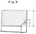
- the shape of the inner portion 24 of end face 20 is a flat surface in the above embodiment, but, as shown in Fig. 3, the inner circumferential edge of the inner portion 24 may be chamfered in a taper shape.
- t2 be a distance along the radial direction from a border line between this taper face 28 and the other part (main part) of the inner portion 24 to the inner circumference of the tubular member 12, and ⁇ 2 be an angle between a face formed by the other part of the inner portion 24 and the generatrix of the taper face 28.
- This distance t2 is dependent on the distance t1 as described above, and is set normally in the range of 0.05t1 ⁇ t2 ⁇ 0.5t1, preferably in the range of 0.1t1 ⁇ t2 ⁇ 0.4t1. Further, ⁇ 2 is set normally in the range of 10° ⁇ ⁇ 2 ⁇ 75°, preferably in the range of 20° ⁇ ⁇ 2 ⁇ 60°, more preferably in the range of 30° ⁇ ⁇ 2 ⁇ 45°. These are conditions which were obtained by experiments.
- step faces 30, 32 may be formed by cutting or grinding in the portion adjacent to the inner circumferential edge of the inner portion 24 in the end face 20 of tubular member 12.
- the area of these step faces 30, 32 is determined as considerably smaller than the other portion of the inner portion 24.
- these step faces 30, 32 are perpendicular to the center axis of tubular member 12. When such step faces 30, 32 are formed, the amount of projection of the bead also becomes very small.
- polyphenylene sulfide pipes 25A manufactured by Kureha Kagaku Kogyo: wall thickness 2.4 mm
- End faces of the pipes were processed in the shape shown in Fig. 2. This time, the end faces were processed so that the above t1 became 1.2 mm, D 0.3 mm, and ⁇ 1 75°.
- the non-contact-type welding apparatus having the heater composed of the brass heating plate and rod heater, welding was carried out under such conditions that the surface temperature of the heating plate was 470 °C, the distance from the end face of each pipe to the opposed heating plate 1 mm, the heating time 30 seconds, the press contact time 120 seconds, and the press contact pressure 600 kPa. As a result, a bead formed on the inner surface of the welded pipes was projected 0.5 mm from the inner circumference, having substantially a uniform shape in the circumferential direction. Also, the weld strength obtained according to JIS K6776 was 60 MPa.
- the welding apparatus is not limited to the illustrated apparatus insofar as it can be applied to the non-contact-type welding method.
- the heater comprising the heating plate as a heating method can be replaced by a heater of the infrared heating type.
- the present invention can apply to the contact-type welding method.
- the present invention can solve or relieve the problems of pressure loss of fluid due to the bead and collection of microorganisms etc.
Landscapes
- Engineering & Computer Science (AREA)
- Mechanical Engineering (AREA)
- Physics & Mathematics (AREA)
- Thermal Sciences (AREA)
- Lining Or Joining Of Plastics Or The Like (AREA)
Applications Claiming Priority (2)
| Application Number | Priority Date | Filing Date | Title |
|---|---|---|---|
| JP35009693 | 1993-12-28 | ||
| JP350096/93 | 1993-12-28 |
Publications (2)
| Publication Number | Publication Date |
|---|---|
| EP0662389A2 true EP0662389A2 (de) | 1995-07-12 |
| EP0662389A3 EP0662389A3 (de) | 1996-08-21 |
Family
ID=18408211
Family Applications (1)
| Application Number | Title | Priority Date | Filing Date |
|---|---|---|---|
| EP94309840A Withdrawn EP0662389A3 (de) | 1993-12-28 | 1994-12-28 | Verfahren zum Verschweissen von rohrförmigen Teilen. |
Country Status (1)
| Country | Link |
|---|---|
| EP (1) | EP0662389A3 (de) |
Cited By (4)
| Publication number | Priority date | Publication date | Assignee | Title |
|---|---|---|---|---|
| EP1859919A3 (de) * | 2006-05-24 | 2010-03-03 | Heateflex Corporation | Geschweisste Rohrfittings mit Schweisswulstabdeckung |
| US7681924B2 (en) * | 2002-03-08 | 2010-03-23 | Fast Fusion, Llc | Fused butt joint for plastic pipe |
| DE102015109183A1 (de) | 2015-06-10 | 2016-12-15 | Fachhochschule Schmalkalden | Verfahren zum Verbinden von zwei Fügepartnern aus Kunststoff |
| BE1027487B1 (nl) * | 2019-12-20 | 2021-03-03 | Brouwerij De Halve Maan | Bierpijpleiding, buizensysteem en werkwijze voor het brouwen van bier |
Family Cites Families (9)
| Publication number | Priority date | Publication date | Assignee | Title |
|---|---|---|---|---|
| FR1416625A (fr) * | 1964-10-21 | 1965-11-05 | Shell Int Research | Procédé pour le soudage en bout d'éléments thermoplastiques, éléments thermoplastiques prévus pour être soudés en bout par ce procédé et joint thermoplastiquesoudé en bout produit par ce procédé |
| DE1779103A1 (de) * | 1968-07-06 | 1971-08-19 | Ver Deutsche Metallwerke Ag | Verfahren zum Schweissen von Kunststoffkoerpern und dadurch gebildete Schweissnaht |
| JPS58199119A (ja) * | 1982-05-17 | 1983-11-19 | Dainichi Nippon Cables Ltd | 水架橋性ポリオレフインパイプの接続方法 |
| DE3510552A1 (de) * | 1985-03-22 | 1986-09-25 | Verlinden, Marius A. J., Antwerpen | Anschweissbare kunststofformteile |
| DE8612217U1 (de) * | 1986-05-03 | 1986-08-21 | HR Plastik-Beratungsbüro GmbH, 4459 Ringe | Kunststoffplatte mit einer Schweißkante |
| DE3634793A1 (de) * | 1986-10-11 | 1988-04-14 | Urban Maschinenbau | Verfahren zum verschweissen von kunststoffprofilen |
| DE3708705A1 (de) * | 1987-03-18 | 1988-10-06 | Gruber Alois & Sohn Agru | Verfahren und vorrichtung zum verschweissen rohrfoermiger kunststoffteile |
| JPH02106325A (ja) * | 1988-10-14 | 1990-04-18 | Takiron Co Ltd | 合成樹脂パイプの接合方法並びにその接合装置 |
| US5328541A (en) * | 1991-12-11 | 1994-07-12 | Kureha Kagaku Kogyo Kabushiki Kaisha | Method of welding tubular products of polyarylene sulfide and welded tubular structure |
-
1994
- 1994-12-28 EP EP94309840A patent/EP0662389A3/de not_active Withdrawn
Cited By (6)
| Publication number | Priority date | Publication date | Assignee | Title |
|---|---|---|---|---|
| US7681924B2 (en) * | 2002-03-08 | 2010-03-23 | Fast Fusion, Llc | Fused butt joint for plastic pipe |
| EP1859919A3 (de) * | 2006-05-24 | 2010-03-03 | Heateflex Corporation | Geschweisste Rohrfittings mit Schweisswulstabdeckung |
| US8349122B2 (en) | 2006-05-24 | 2013-01-08 | Heateflex Corporation | Fusion welding fittings with weld bead cover |
| US10281077B2 (en) | 2006-05-24 | 2019-05-07 | Heateflex Corporation | Fusion welding fittings with weld bead cover |
| DE102015109183A1 (de) | 2015-06-10 | 2016-12-15 | Fachhochschule Schmalkalden | Verfahren zum Verbinden von zwei Fügepartnern aus Kunststoff |
| BE1027487B1 (nl) * | 2019-12-20 | 2021-03-03 | Brouwerij De Halve Maan | Bierpijpleiding, buizensysteem en werkwijze voor het brouwen van bier |
Also Published As
| Publication number | Publication date |
|---|---|
| EP0662389A3 (de) | 1996-08-21 |
Similar Documents
| Publication | Publication Date | Title |
|---|---|---|
| US3788928A (en) | Method of forming a lap joint between tubular articles of thermoplastic material | |
| CA1163412A (en) | Method for joining together thermoplastics pipes and pipe fittings | |
| US6131954A (en) | Weldable couple for electrofusion coupling of profile wall thermoplastic pipes without a separate coupler | |
| US4176274A (en) | Method of coupling plastic pipes by welding and a connection piece for coupling same | |
| US5820720A (en) | Method of and apparatus for electrofusion coupling of thermoplastic pipes | |
| DE69416921T2 (de) | Verfahren und Vorrichtung zum Verbinden von Kunststoffrohren | |
| JP2719583B2 (ja) | 強化熱可塑性パイプを接合する方法 | |
| EP0186168B1 (de) | Verfahren zum Verbinden von Kunststoffrohren | |
| US4396213A (en) | Method of joining pipe ends and joint formed thereby | |
| US3286341A (en) | Method of making a tubular joint | |
| US5730189A (en) | Internally and externally enhanced wielded tube | |
| US20010048223A1 (en) | Method of and joint for coupling thermoplastic pipes | |
| US20030168771A1 (en) | Beveled cutter | |
| US5188697A (en) | Process and device for welding of tubular plastic parts | |
| US6521072B1 (en) | Method of coupling profile wall thermoplastic pipes | |
| US4288266A (en) | Method for heated tool butt welding of tube and pipe of thermoplastic materials | |
| JP3261531B2 (ja) | 中空プラスチック部材の溶融接合方法 | |
| JP2548374B2 (ja) | 容器及びその製造装置 | |
| JPH07232379A (ja) | 管状部材の溶着方法 | |
| HK1006956B (en) | Method of joining hollow plastics members by fusion | |
| EP1752699A2 (de) | Leitungsverbund zwischen einem Fitting und einem Verbundrohr sowie ein Verfahren zur Herstellung des Leitungsverbundes | |
| TWI736767B (zh) | 樹脂製管構件、樹脂製管構件之製造方法、樹脂製管接頭及樹脂製配管 | |
| GB2025556A (en) | Joining together pipe ends of thermoplasticmaterial | |
| AU659109B2 (en) | Welding apparatus | |
| GB2194915A (en) | Induction welding of plastics components |
Legal Events
| Date | Code | Title | Description |
|---|---|---|---|
| PUAI | Public reference made under article 153(3) epc to a published international application that has entered the european phase |
Free format text: ORIGINAL CODE: 0009012 |
|
| AK | Designated contracting states |
Kind code of ref document: A2 Designated state(s): AT DE FR GB |
|
| PUAL | Search report despatched |
Free format text: ORIGINAL CODE: 0009013 |
|
| AK | Designated contracting states |
Kind code of ref document: A3 Designated state(s): AT DE FR GB |
|
| STAA | Information on the status of an ep patent application or granted ep patent |
Free format text: STATUS: THE APPLICATION IS DEEMED TO BE WITHDRAWN |
|
| 18D | Application deemed to be withdrawn |
Effective date: 19970222 |