EP0662408B2 - Aufroller für ein Gurtschloss - Google Patents
Aufroller für ein Gurtschloss Download PDFInfo
- Publication number
- EP0662408B2 EP0662408B2 EP94120488A EP94120488A EP0662408B2 EP 0662408 B2 EP0662408 B2 EP 0662408B2 EP 94120488 A EP94120488 A EP 94120488A EP 94120488 A EP94120488 A EP 94120488A EP 0662408 B2 EP0662408 B2 EP 0662408B2
- Authority
- EP
- European Patent Office
- Prior art keywords
- seat belt
- diameter pulley
- drive source
- elongated member
- stroke
- Prior art date
- Legal status (The legal status is an assumption and is not a legal conclusion. Google has not performed a legal analysis and makes no representation as to the accuracy of the status listed.)
- Expired - Lifetime
Links
- 230000005540 biological transmission Effects 0.000 claims description 6
- 239000002360 explosive Substances 0.000 claims 1
- 238000004804 winding Methods 0.000 claims 1
- 230000001133 acceleration Effects 0.000 description 3
- 230000006835 compression Effects 0.000 description 3
- 238000007906 compression Methods 0.000 description 3
- 238000010276 construction Methods 0.000 description 3
Images


Classifications
-
- B—PERFORMING OPERATIONS; TRANSPORTING
- B60—VEHICLES IN GENERAL
- B60R—VEHICLES, VEHICLE FITTINGS, OR VEHICLE PARTS, NOT OTHERWISE PROVIDED FOR
- B60R22/00—Safety belts or body harnesses in vehicles
- B60R22/18—Anchoring devices
- B60R22/195—Anchoring devices with means to tension the belt in an emergency, e.g. means of the through-anchor or splitted reel type
- B60R22/1952—Transmission of tensioning power by cable; Return motion locking means therefor
Definitions
- the present invention relates to a tensioner according to the preamble of claim 1.
- a tensioner according to the preamble of claim 1 is known from DE-C-1 933 872.
- the problem to be solved is to modify the known device for use besides a seat and in combination with a seat belt buckle.
- a mechanical buckle retractor which retracts, toward a lower side of a vehicle body, a buckle engaged with a tongue plate which is mounted at an intermediate portion of the webbing.
- a lock plate 76 is connected to an anchor portion 74 of a buckle 72.
- One end of a wire 80 is mounted at a lower end portion of the lock plate 76 via a connecting piece 78.
- An intermediate portion of the wire 80 is wound around a pulley 82 provided at a front side of a direction in which the buckle 72 is retracted, and the other end of the wire 80 is connected to a piston 86 disposed within a cylinder 84.
- the cylinder 84 is equipped with a gas generator 88 which operates at the time of a sudden deceleration of a vehicle so as to generate a large amount of gas.
- the piston 86 moves within the cylinder 84 and applies tension to the wire 80, so that the wire 80 is forcibly pulled in and the lock plate 76 is retracted together with the buckle 72.
- the present invention was developed in light of the above circumstances and it is an object of the present invention to provide a buckle retractor which can sufficiently maintain a space for the amount by which the buckle is retracted and which is of a small size so that a large configuration space is not required.
- a tensioner known from DE 41 13 094 A1
- the drive is equipped with a piston which is movably guided within a cylinder. Said piston is disengaged from the cylinder at a time of a sudden deceleration of a vehicle. The disengagement of the piston is transferred to the seat belt by virtue of transmission means.
- DE 41 27 957 A1 defines a solution how to embody a transmission between a reversion tensioner and a webbing device.
- a structure can be used in which wires respectively wound around a pulley having a small diameter portion and a large diameter portion are connected to the drive source and the seat belt, respectively, the small diameter portion is rotated by a driving force from the drive source, and the wire connected to the seat belt is wound around the large diameter portion.
- various stroke increasing means can also be used: one of them is that a pair of gear wheels which mesh each other and have different pitch diameters are used, the small diameter gear being driven and the large diameter gear pulling a seat belt; another is that a link having different lengths from a center line of rotation is used, a short turning radius portion being driven and a long turning radius portion pulling a seat belt; and still other is that a cam is used.
- Fig. 1 is a partially broken front view illustrating an overall construction of a buckle retractor according to an embodiment of the present invention.
- Fig. 2 is a front view corresponding to Fig. 1 and illustrating a state in which the buckle retractor according to the embodiment of the present invention is being actuated.
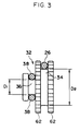
- Fig. 3 is a side view illustrating a large diameter portion and a small diameter portion of a pulley of the buckle retractor according to the embodiment of the present invention.
- Fig. 4 is a cross-sectional view illustrating an overall construction of a conventional buckle retractor.
- arrows "FR" and “UP” shown in the accompanying drawings respectively represent the forward direction of a vehicle and the upward direction thereof.
- Fig. 1 shows a partially broken front view of an overall construction of a buckle retractor 10 according to an embodiment of the present invention.
- a main body portion 12 of the buckle retractor 10 is mounted to a side surface of an unillustrated occupant's seat by a bolt 14.
- An elongated rectangular guide portion 16 is formed at an end portion of the main body portion 12 at a rear side of a vehicle.
- a plate 18 is accommodated within the guide portion 16 so as to be movable.
- An anchor portion 24 of a buckle 22 is connected to an upper end portion of the plate 18 via a stepped bolt 20, so that the buckle 22 can be moved together with the plate 18.
- one end of a wire 26 as a first wire is connected to a lower end portion of the plate 18 via a connecting piece 28, while the other end of the wire 26 is connected to a pulley 32 via a connecting piece 30.
- the pulley 32 is formed into a two-step structure in which, as shown in Fig. 3, a large diameter portion 34 and a small diameter portion 36 are integrally provided.
- the pulley 32 is mounted to the main body portion 12 below the guide portion 16 so as to be rotatable.
- the above-described other end of the wire 26 is connected to the large diameter portion 34 of the pulley 32 via the connecting piece 30. Accordingly, when the pulley 32 rotates, the large diameter portion 34 can wind up the wire 26.
- one end of a wire 38 as a second wire is connected to the small diameter portion 36 of the pulley 32 via a connecting piece 40. Further, one proximal end portion of the wire 38 is wound around the small diameter portion 36 by a predetermined length. Accordingly, when the wire 38 is pulled and the portion of the wire 38 being wound is pulled out, the pulley 32 is rotated.
- the other end of the wire 38 wound around the small diameter portion 36 of the pulley 32 is connected to a piston 44 via a connecting piece 42.
- the piston 44 is accommodated within a cylinder 46 fixed to a portion of the main body portion 12 at a front side of the vehicle, and can be moved together with the wire 38 within the cylinder 46.
- a gas generator 48 is disposed above the cylinder 46 at a rear-side lateral end portion of the vehicle. Accommodated within the gas generator 48 are an acceleration sensor 50 which senses a vehicle acceleration, and an inflator 54 with a detonator 52.
- the inflator 54 communicates with a space of the cylinder 46 at a back side of the piston 44 via a passage 56.
- a ratchet wheel 58 which forms a rotation preventing means is provided so as to be integrated with the outside of the above-described pulley 32.
- a fastening pawl 60 is mounted to the main body portion 12 in the vicinity of the ratchet wheel 58 so as to face the ratchet wheel 58.
- Sawtoothed external teeth 62 are formed around the ratchet wheel 58.
- the fastening pawl 60 engages with one of these external teeth 62. Namely, by causing the fastening pawl 60 to engage with these external teeth 62, only rotation of the ratchet wheel 58 (i.e., pulley 32) in a direction in which the wire 26 is retracted and a direction in which the wire 38 is withdrawn or pulled out (i.e., the direction of arrow A) is allowed, and the rotation thereof in a direction in which the wire 26 is pulled out and in a direction in which the wire 38 is retracted (i.e., the direction of arrow B) is prevented.
- a compression spring 66 is interposed between the fastening pawl 60 and a bracket 64 of the main body portion 12 so that the fastening pawl 60 is constantly urged toward the external teeth 62 of the ratchet wheel 58.
- the gas generator 48 is in a non-operating state and the fastening pawl 60 urged by the compression spring 66 engages with the external teeth 62 of the ratchet wheel 58.
- the ratchet wheel 58 i.e., pulley 32, is prevented from rotating in the direction in which the wire 26 is pulled out and the direction in which the wire 38 is retracted (i.e., the direction of arrow B).
- an occupant is reliably restrained by a webbing fastened to the buckle 22 via a tongue plate.
- an elastic member such as a plate spring may be provided between the plate 18 and the guide portion 16, or the plate 18 may be mounted to the main body portion 12 via a pin which is to be sheared off by a large load.
- the acceleration sensor 50 of the gas generator 48 operates so that the detonator 52 is ignited and a large amount of gas is generated from the inflator 54.
- the large amount of gas flows into the cylinder 46 at the back side of the piston 44 via the passage 56.
- the piston 44 disposed within the cylinder 46 is moved together with the wire 38.
- the movement of the piston 44 causes tension to be applied to the wire 38, and the pulley 32 is rotated (the direction of arrow A).
- tension is applied to the wire 26 and the plate 18 is moved along the guide plate 16 so that the buckle 22 is retracted. Accordingly, the webbing fastened to the buckle 22 via the tongue plate is applied closely to the occupant so that the occupant is reliably restrained.
- the fastening pawl 60 urged by the compression spring 66 engages with the external teeth 62 of the ratchet wheel 58, and the ratchet wheel 58, i.e., pulley 32, is prevented from rotating in the direction in which the wire 26 is pulled out and the direction in which the wire 38 is retracted (i.e., the direction of arrow B). For this reason, there is no possibility that the buckle 22 be pulled out again.
- the buckle 22 is connected to the large diameter portion 34 of the pulley 32 via the wire 26 and the piston 44 is connected to the small diameter portion 36 of the pulley 32 via the wire 38.
- the moving stroke of the piston 44 is extended in accordance with the dimensional ratio of the small diameter portion 36 and the large diameter portion 34 and is transmitted to the buckle 22.
- it is sufficient that the moving stroke of the piston 44 for maintaining the amount by which the buckle 22 is retracted is markedly small.
- the moving stroke of the piston 44 for maintaining the amount by which the buckle 22 is retracted is small in accordance with the dimensional ratio of the small diameter portion 36 and the large diameter portion 34 of the pulley 32. Namely, even if the moving stroke of the piston 44 is small, the amount by which the buckle 22 is retracted can be sufficiently maintained. Accordingly, it becomes possible that the overall length of the cylinder 46 be shortened, and the present apparatus can be made small so that a large configuration space is not required.
- the amount by which the buckle 22 is retracted can be sufficiently maintained and the small-size retractor can be realized so that the large configuration space is not required. Moreover, assembling efficiency does not deteriorate and the present retractor can also be used even in a small-size vehicle, so that an applicable range also extends.
- tension of the piston 44 may be transmitted to the pulley 32 via the rack.
Landscapes
- Engineering & Computer Science (AREA)
- Mechanical Engineering (AREA)
- Automotive Seat Belt Assembly (AREA)
Claims (9)
- Straffervorrichtung, die bei einem Sitzgurt zu einem Zeitpunkt plötzlicher Verzögerung eines Fahrzeugs eine Zugspannung bewirkt, mit einem Antrieb, der zum Zeitpunkt einer plötzlichen Verzögerung des Fahrzeugs betätigt wird, und mit Übertragungsmitteln (26, 38), die eine Antriebskraft des Antriebs auf einen Bereich (22) des Sitzgurtes bringen und so eine Zugspannung auf den Sitzgurt ausüben, wobei der Antrieb (48) ein langgestrecktes Element (38, 26), das als Übertragungsmittel dient, durch eine Sprengkraft zieht und dass das langgestreckte Element (38, 26) die Zugspannung auf ein Gurtschloss (22) des Sitzgurtes überträgt, wobei die Straffervorrichtung ein Hubverlängerungsmittel (32) aufweist, das einen Antriebshub vom Antrieb (48) verlängert und den Sitzgurt um einen Antriebshub, der größer als der Antriebshub vom Antrieb ist, zieht, um so einen großen den Sitzgurt ziehenden Hub auch dann zu erreichen, wenn der Antriebshub des Antriebs klein ist, und wobei das langgestreckte Element um eine durchmesserkleine Seilscheibe (36) und eine durchmessergroße Seilscheibe (34) gewunden ist, und wenn diese Seilscheiben (36, 34) miteinander verbunden sind, der Antriebshub des Antriebs verlängert und auf den Sitzgurt (22) übertragen wird,
dadurch gekennzeichnet, dass die Zugspannung auf ein Gurtschloss (22) des Sitzgurtes übertragen wird, das Übertragungsmittel (26, 38) zwei Seilteile (38, 26) aufweist, wobei das eine Seilteil (38) mit dem Antrieb (48) verbunden ist und das andere Seilteil (26) mit dem Sitzgurtschloss (22) verbunden ist, wobei die durchmesserkleine Seilscheibe (36) und die durchmessergroße Seilscheibe (34) koaxial miteinander verbunden sind. - Straffervorrichtung nach Anspruch 1, dadurch gekennzeichnet, dass das langgestreckte Element (38, 26) flexibel ist und dass ein Zwischenbereich des langgestreckten Elementes um ein Wickelelement (32) gewunden ist, so dass die Richtung, in welcher das langgestreckte Element gezogen wird, geändert ist.
- Straffervorrichtung nach Anspruch 1, dadurch gekennzeichnet, dass das langgestreckte Element (38, 26) flexibel ist und dass ein Zwischenbereich des langgestreckten Elementes um eine Seilscheibe (32) gewunden ist, die als Hubverlängerungsmittel dient.
- Straffervorrichtung nach einem der vorhergehenden Ansprüche, dadurch gekennzeichnet, dass ein Ende des Seils (38) mit der durchmesserkleinen Seilscheibe (36) nach der Wicklung um die durchmesserkleine Seilscheibe fest verbunden ist und ein Ende des anderen Seiles (26) mit der durchmessergroßen Seilscheibe (34) fest verbunden ist.
- Straffervorrichtung nach einem der vorhergehenden Ansprüche, dadurch gekennzeichnet, dass die einen Endbereiche der beiden Seilteile (38, 26) um die koaxiale durchmesserkleine Seilscheibe (36) bzw. um die durchmessergroße Seilscheibe (34) in entgegengesetzten Richtungen gewunden sind und dass dann, wenn ein Seil (26) aus der durchmesserkleinen Seilscheibe herausgezogen ist, ein anderes Seil (38) um die durchmessergroße Seilscheibe gewunden ist.
- Straffervorrichtung nach einem der vorhergehenden Ansprüche, dadurch gekennzeichnet, dass sie ferner ein Rotationsumkehrungsverhinderungsmittel (60) aufweist, das verhindert, dass die Seile (38, 26) in eine Richtung, die derjenigen der Zugspannung des Antriebs entgegengerichtet ist, zurückgezogen werden.
- Straffervorrichtung nach Anspruch 6, dadurch gekennzeichnet, dass das Rotationsumkehrungsverhinderungsmittel (60) eine Rotation der Seilscheiben (32) verhindert.
- Straffervorrichtung nach Anspruch 6, dadurch gekennzeichnet, dass das Rotationsumkehrungsverhinderungsmittel (60) derart aufgebaut ist, dass eine Halteklinke (60) mit den Seilscheiben (32) in Eingriff kommt und so die Rotation der Seilscheiben verhindert.
- Straffervorrichtung nach Anspruch 6, dadurch gekennzeichnet, dass das Rotationsumkehrungsverhinderungsmittel eine Rotation der Seilscheiben (32) nur in eine Richtung dadurch ermöglicht, dass eine Sperrklinke (60) mit einem Sperrklinkenrad (58), das am Außenumfang der Seilscheiben vorgesehen ist, durch eine auf ein elastisches Element wirkende Druckkraft in Eingriff bringbar ist.
Applications Claiming Priority (3)
| Application Number | Priority Date | Filing Date | Title |
|---|---|---|---|
| JP6001289A JP2981393B2 (ja) | 1994-01-11 | 1994-01-11 | バックル引込み装置 |
| JP128994 | 1994-01-11 | ||
| JP1289/94 | 1994-01-11 |
Publications (3)
| Publication Number | Publication Date |
|---|---|
| EP0662408A1 EP0662408A1 (de) | 1995-07-12 |
| EP0662408B1 EP0662408B1 (de) | 1997-04-23 |
| EP0662408B2 true EP0662408B2 (de) | 2000-09-06 |
Family
ID=11497303
Family Applications (1)
| Application Number | Title | Priority Date | Filing Date |
|---|---|---|---|
| EP94120488A Expired - Lifetime EP0662408B2 (de) | 1994-01-11 | 1994-12-23 | Aufroller für ein Gurtschloss |
Country Status (4)
| Country | Link |
|---|---|
| US (1) | US5634690A (de) |
| EP (1) | EP0662408B2 (de) |
| JP (1) | JP2981393B2 (de) |
| DE (1) | DE69402817T3 (de) |
Families Citing this family (28)
| Publication number | Priority date | Publication date | Assignee | Title |
|---|---|---|---|---|
| US5788025A (en) * | 1994-12-22 | 1998-08-04 | Kabushiki Kaisha Tokai-Rika-Denki-Seisakusho | Reversing preventing device |
| DE19546280C2 (de) * | 1995-12-12 | 2000-07-27 | Autolive Dev Ab Vargarda | Strammeinrichtung für Sicherheitsgurte mit einer Exzenterverriegelung |
| DE29605818U1 (de) * | 1996-03-28 | 1996-07-25 | Trw Occupant Restraint Systems Gmbh, 73551 Alfdorf | Fahrzeuginsassen-Rückhaltesystem mit einem Gurtstraffer |
| JP2963883B2 (ja) * | 1996-04-23 | 1999-10-18 | ティーアールダブリュ オキュパント リストレイント システムズ ゲゼルシャフト ミット ベシュレンクテル ハフツング | 一体化されたベルトテンショナーを備えている車両シート |
| FR2755924B1 (fr) * | 1996-11-18 | 1998-12-18 | Renault | Caisse de vehicule automobile a rideau separant le poste de conduite de l'espace chargement |
| GB2323769B (en) * | 1997-04-04 | 2001-05-30 | Autoliv Dev | Improvements in or relating to a vehicle seat belt pretensioner |
| GB2330334A (en) * | 1997-06-02 | 1999-04-21 | Alliedsignal Ltd | Buckle pretensioner for a vehicle |
| US5906327A (en) * | 1998-02-17 | 1999-05-25 | Breed Automotive Technology, Inc. | Pretensioner or belt tightener |
| GB9808610D0 (en) * | 1998-04-22 | 1998-06-24 | Breed Automotive Tech | Pretensioner |
| DE29821272U1 (de) * | 1998-11-27 | 1999-03-25 | TRW Occupant Restraint Systems GmbH & Co. KG, 73553 Alfdorf | Gurtsystem zum Zurückhalten eines Fahrzeuginsassen |
| US6264281B1 (en) * | 1999-08-25 | 2001-07-24 | Daimlerchrysler Corporation | Seat belt buckle pretensioner mounting mechanism |
| DE20111638U1 (de) * | 2001-07-12 | 2001-09-27 | Breed Automotive Technology, Inc., Lakeland, Fla. | Linearstrafferantrieb zum Straffen eines Fahrzeugsicherheitsgurtes |
| US7188868B2 (en) | 2001-08-23 | 2007-03-13 | Nhk Spring Co., Ltd. | Seat belt pretensioner |
| DE50303917D1 (de) * | 2002-09-04 | 2006-08-03 | Takata Petri Gmbh Ulm | Gurtschlossstraffer |
| DE10310019A1 (de) * | 2003-02-28 | 2004-09-09 | Takata-Petri (Ulm) Gmbh | Gurtaufroller für einen Sicherheitsgurt |
| JP4854657B2 (ja) * | 2004-04-22 | 2012-01-18 | オートリブ ディヴェロプメント アクチボラゲット | 二重ケーブル取入れ口を備えるケーブル引締め装置 |
| JP4425065B2 (ja) * | 2004-06-08 | 2010-03-03 | 株式会社東海理化電機製作所 | バックルプリテンショナ装置 |
| US7380832B2 (en) * | 2005-04-05 | 2008-06-03 | Takata Seat Belts, Inc. | Pretensioner with integrated gas generator |
| JP5182843B2 (ja) * | 2007-02-15 | 2013-04-17 | テイ・エス テック株式会社 | 車両用シート |
| US7784831B2 (en) * | 2008-06-27 | 2010-08-31 | Gm Global Technology Operations, Inc. | Seat belt load limiting device |
| KR100968829B1 (ko) * | 2008-08-29 | 2010-07-08 | 현대자동차주식회사 | 시트벨트 프리텐셔너 |
| US9346429B2 (en) * | 2014-03-06 | 2016-05-24 | Disney Enterprises, Inc. | Passenger restraint pawl and ratchet assembly with positive engagement |
| US9827947B2 (en) | 2016-02-10 | 2017-11-28 | Ford Global Technologies, Llc | Load limiting seat belt buckle assemblies |
| JP2018034550A (ja) * | 2016-08-29 | 2018-03-08 | 株式会社東海理化電機製作所 | バックル装置 |
| JP6516794B2 (ja) * | 2017-06-28 | 2019-05-22 | 株式会社タチエス | 車両用シート |
| US11390244B2 (en) * | 2019-12-10 | 2022-07-19 | GM Global Technology Operations LLC | Cam based seat belt pretensioner |
| JP7365229B2 (ja) * | 2019-12-27 | 2023-10-19 | 株式会社Subaru | シートベルト装置 |
| DE102021103334A1 (de) * | 2021-02-12 | 2022-08-18 | Bayerische Motoren Werke Aktiengesellschaft | Sicherheitsgurtschlosseinheit |
Citations (3)
| Publication number | Priority date | Publication date | Assignee | Title |
|---|---|---|---|---|
| DE1933872C (de) † | 1968-07-16 | 1973-03-29 | Pacific Scientific Co., Commerce City, Calif. (V.StA.) | Aufwickelvorrichtung für Sicherheitsgurte |
| DE4113094A1 (de) † | 1990-04-23 | 1991-11-07 | Takata Corp | Gurtstraffer fuer einen sicherheitsgurt in einem fahrzeug |
| DE4127957A1 (de) † | 1991-08-23 | 1993-02-25 | Hs Tech & Design | Kupplung zum uebertragen der auf ein zugseil wirkenden rueckstrafferbewegung auf eine gurtbandspule eines sicherheitsgurtautomaten |
Family Cites Families (24)
| Publication number | Priority date | Publication date | Assignee | Title |
|---|---|---|---|---|
| US3043093A (en) * | 1960-03-08 | 1962-07-10 | Albert M Stott | Cable coupled actuator |
| JPS56141637U (de) * | 1980-03-03 | 1981-10-26 | ||
| DE3131637C2 (de) * | 1980-10-06 | 1986-10-02 | TRW Repa GmbH, 7077 Alfdorf | Rückstrammer für Sicherheitsgurtautomaten |
| DE3329687A1 (de) * | 1983-08-17 | 1985-03-07 | Volkswagenwerk Ag, 3180 Wolfsburg | Vorrichtung zur sicherheitsgurt-straffung |
| US4932283A (en) * | 1987-11-04 | 1990-06-12 | Kabushiki Kaisha Tokai-Rika-Denki-Seisakusho | Locking apparatus for shift lever |
| JPH01257642A (ja) * | 1988-04-08 | 1989-10-13 | Honda Motor Co Ltd | シートベルトのプリローダ装置 |
| WO1990000236A1 (en) * | 1988-06-28 | 1990-01-11 | A.O. Smith Corporation | Composite thread coupling for reinforced pipe |
| JPH0262760A (ja) * | 1988-08-30 | 1990-03-02 | Matsushita Electric Ind Co Ltd | 記録再生装置 |
| US5004178A (en) * | 1988-10-17 | 1991-04-02 | Jidosha Denki Kogyo K.K. | Seat belt apparatus |
| DE3842333C1 (de) * | 1988-12-16 | 1990-04-12 | Daimler-Benz Aktiengesellschaft, 7000 Stuttgart, De | |
| SE463406B (sv) * | 1989-04-06 | 1990-11-19 | Karlo Smit | Foerfarande och anordning foer kraftavlastning medelst saekerhetsbaelten vid kraftiga retardationer |
| JPH03121947A (ja) * | 1989-10-04 | 1991-05-23 | Seiyoo Denshi Kk | 事故現場記録装置 |
| US5058462A (en) * | 1990-01-22 | 1991-10-22 | Teleflex Incorporated | Parklock cable lock box |
| US5031737A (en) * | 1990-01-29 | 1991-07-16 | General Motors Corporation | Transmission/brake interlock |
| JPH03292239A (ja) * | 1990-04-06 | 1991-12-24 | Honda Lock Mfg Co Ltd | シートベルト緊張装置 |
| JPH04103453A (ja) * | 1990-08-24 | 1992-04-06 | Takata Kk | バネ式プリテンショナーのトリガー |
| JP2770563B2 (ja) * | 1990-09-18 | 1998-07-02 | 日産自動車株式会社 | 車両乗員保護装置 |
| JP2933239B2 (ja) * | 1990-11-21 | 1999-08-09 | タカタ株式会社 | リトラクタ軸回転式プリテンショナ |
| JPH0554117A (ja) * | 1991-08-23 | 1993-03-05 | Fujitsu General Ltd | 画像処理装置 |
| DE4136623A1 (de) * | 1991-11-07 | 1993-05-13 | Trw Repa Gmbh | Gurtstraffer fuer fahrzeug-sicherheitsgurtsysteme |
| DE4226083C2 (de) * | 1992-08-06 | 2000-08-31 | Hs Tech & Design | Vorrichtung zur Übertragung der Antriebskraft eines Gurtstraffers eines Sicherheitsgurtes |
| JP3234016B2 (ja) * | 1992-12-17 | 2001-12-04 | 津田工業株式会社 | 自動変速機用シフトロック装置 |
| JP3109319B2 (ja) * | 1993-02-26 | 2000-11-13 | スズキ株式会社 | ケーブルの位置調整構造 |
| US5423598A (en) * | 1993-06-11 | 1995-06-13 | Trw Vehicle Safety Systems Inc. | Safety apparatus |
-
1994
- 1994-01-11 JP JP6001289A patent/JP2981393B2/ja not_active Expired - Fee Related
- 1994-12-22 US US08/362,115 patent/US5634690A/en not_active Expired - Fee Related
- 1994-12-23 EP EP94120488A patent/EP0662408B2/de not_active Expired - Lifetime
- 1994-12-23 DE DE69402817T patent/DE69402817T3/de not_active Expired - Fee Related
Patent Citations (3)
| Publication number | Priority date | Publication date | Assignee | Title |
|---|---|---|---|---|
| DE1933872C (de) † | 1968-07-16 | 1973-03-29 | Pacific Scientific Co., Commerce City, Calif. (V.StA.) | Aufwickelvorrichtung für Sicherheitsgurte |
| DE4113094A1 (de) † | 1990-04-23 | 1991-11-07 | Takata Corp | Gurtstraffer fuer einen sicherheitsgurt in einem fahrzeug |
| DE4127957A1 (de) † | 1991-08-23 | 1993-02-25 | Hs Tech & Design | Kupplung zum uebertragen der auf ein zugseil wirkenden rueckstrafferbewegung auf eine gurtbandspule eines sicherheitsgurtautomaten |
Also Published As
| Publication number | Publication date |
|---|---|
| JP2981393B2 (ja) | 1999-11-22 |
| JPH07196009A (ja) | 1995-08-01 |
| DE69402817T2 (de) | 1997-12-18 |
| US5634690A (en) | 1997-06-03 |
| EP0662408A1 (de) | 1995-07-12 |
| DE69402817T3 (de) | 2000-11-23 |
| DE69402817D1 (de) | 1997-05-28 |
| EP0662408B1 (de) | 1997-04-23 |
Similar Documents
| Publication | Publication Date | Title |
|---|---|---|
| EP0662408B2 (de) | Aufroller für ein Gurtschloss | |
| EP0796180B1 (de) | Sekundärverriegelungseinrichtung für einen aufroller mit strammvorrichtung | |
| CN100402353C (zh) | 安全带收缩器 | |
| JP2500192B2 (ja) | 自動車安全ベルトのベルトリトラクタ― | |
| US20020074441A1 (en) | Pretensioner drive | |
| US5839686A (en) | Chain driven pretensioner and retractor | |
| EP0641691A1 (de) | Sicherheitsgurt-Strammvorrichtung | |
| US6966518B2 (en) | Clutch for tension reducer | |
| US5697571A (en) | Chain link rack pretensioner | |
| EP1024064A2 (de) | Bobine d'enrouleur | |
| JP4662214B2 (ja) | シートベルトリトラクタ | |
| US5782423A (en) | Spiral tube compact pretensioner and retractor | |
| JP3135685B2 (ja) | シートベルト装置のバックルプリテンショナ | |
| KR100254853B1 (ko) | 벨트인장기 | |
| US20030019969A1 (en) | Selectable load limiting seat restraint retractor | |
| CA2316510A1 (en) | Pretensioner integrated with a force transferring apparatus of a seat belt retractor | |
| JPH08198055A (ja) | 逆戻り防止装置 | |
| KR100850922B1 (ko) | 안전벨트 리트랙터의 토션 바 지지 구조 | |
| EP1121277A1 (de) | Mehrpunkt-straffersystem | |
| KR20230038536A (ko) | 벨트 리트랙터 | |
| EP1201513B1 (de) | Weich-Start- Betätigungskolben | |
| US6520443B2 (en) | Pretensioner drive | |
| US20050284976A1 (en) | Method for operating a belt retractor and a belt retractor for a safety belt | |
| US20020140278A1 (en) | Seat restraint tensioner | |
| RU2116902C1 (ru) | Устройство для упреждающего натяжения лямки ремня безопасности транспортного средства |
Legal Events
| Date | Code | Title | Description |
|---|---|---|---|
| PUAI | Public reference made under article 153(3) epc to a published international application that has entered the european phase |
Free format text: ORIGINAL CODE: 0009012 |
|
| AK | Designated contracting states |
Kind code of ref document: A1 Designated state(s): DE FR GB |
|
| 17P | Request for examination filed |
Effective date: 19950701 |
|
| GRAG | Despatch of communication of intention to grant |
Free format text: ORIGINAL CODE: EPIDOS AGRA |
|
| 17Q | First examination report despatched |
Effective date: 19960813 |
|
| GRAH | Despatch of communication of intention to grant a patent |
Free format text: ORIGINAL CODE: EPIDOS IGRA |
|
| GRAH | Despatch of communication of intention to grant a patent |
Free format text: ORIGINAL CODE: EPIDOS IGRA |
|
| GRAA | (expected) grant |
Free format text: ORIGINAL CODE: 0009210 |
|
| AK | Designated contracting states |
Kind code of ref document: B1 Designated state(s): DE FR GB |
|
| REF | Corresponds to: |
Ref document number: 69402817 Country of ref document: DE Date of ref document: 19970528 |
|
| ET | Fr: translation filed | ||
| PLBQ | Unpublished change to opponent data |
Free format text: ORIGINAL CODE: EPIDOS OPPO |
|
| PLBI | Opposition filed |
Free format text: ORIGINAL CODE: 0009260 |
|
| PLBF | Reply of patent proprietor to notice(s) of opposition |
Free format text: ORIGINAL CODE: EPIDOS OBSO |
|
| 26 | Opposition filed |
Opponent name: AUTOLIV DEVELOPMENT AB Effective date: 19980122 |
|
| PLBF | Reply of patent proprietor to notice(s) of opposition |
Free format text: ORIGINAL CODE: EPIDOS OBSO |
|
| PLBF | Reply of patent proprietor to notice(s) of opposition |
Free format text: ORIGINAL CODE: EPIDOS OBSO |
|
| PLBF | Reply of patent proprietor to notice(s) of opposition |
Free format text: ORIGINAL CODE: EPIDOS OBSO |
|
| PLBF | Reply of patent proprietor to notice(s) of opposition |
Free format text: ORIGINAL CODE: EPIDOS OBSO |
|
| PLAW | Interlocutory decision in opposition |
Free format text: ORIGINAL CODE: EPIDOS IDOP |
|
| PLAW | Interlocutory decision in opposition |
Free format text: ORIGINAL CODE: EPIDOS IDOP |
|
| PUAH | Patent maintained in amended form |
Free format text: ORIGINAL CODE: 0009272 |
|
| STAA | Information on the status of an ep patent application or granted ep patent |
Free format text: STATUS: PATENT MAINTAINED AS AMENDED |
|
| 27A | Patent maintained in amended form |
Effective date: 20000906 |
|
| AK | Designated contracting states |
Kind code of ref document: B2 Designated state(s): DE FR GB |
|
| ET3 | Fr: translation filed ** decision concerning opposition | ||
| REG | Reference to a national code |
Ref country code: GB Ref legal event code: IF02 |
|
| PGFP | Annual fee paid to national office [announced via postgrant information from national office to epo] |
Ref country code: GB Payment date: 20071219 Year of fee payment: 14 Ref country code: FR Payment date: 20071210 Year of fee payment: 14 |
|
| PGFP | Annual fee paid to national office [announced via postgrant information from national office to epo] |
Ref country code: DE Payment date: 20071220 Year of fee payment: 14 |
|
| GBPC | Gb: european patent ceased through non-payment of renewal fee |
Effective date: 20081223 |
|
| REG | Reference to a national code |
Ref country code: FR Ref legal event code: ST Effective date: 20090831 |
|
| PG25 | Lapsed in a contracting state [announced via postgrant information from national office to epo] |
Ref country code: DE Free format text: LAPSE BECAUSE OF NON-PAYMENT OF DUE FEES Effective date: 20090701 |
|
| PG25 | Lapsed in a contracting state [announced via postgrant information from national office to epo] |
Ref country code: GB Free format text: LAPSE BECAUSE OF NON-PAYMENT OF DUE FEES Effective date: 20081223 |
|
| PG25 | Lapsed in a contracting state [announced via postgrant information from national office to epo] |
Ref country code: FR Free format text: LAPSE BECAUSE OF NON-PAYMENT OF DUE FEES Effective date: 20081231 |