EP0662555A2 - Ensemble de poignée de porte - Google Patents
Ensemble de poignée de porte Download PDFInfo
- Publication number
- EP0662555A2 EP0662555A2 EP94309690A EP94309690A EP0662555A2 EP 0662555 A2 EP0662555 A2 EP 0662555A2 EP 94309690 A EP94309690 A EP 94309690A EP 94309690 A EP94309690 A EP 94309690A EP 0662555 A2 EP0662555 A2 EP 0662555A2
- Authority
- EP
- European Patent Office
- Prior art keywords
- slider
- cam
- door
- assembly
- stop plate
- Prior art date
- Legal status (The legal status is an assumption and is not a legal conclusion. Google has not performed a legal analysis and makes no representation as to the accuracy of the status listed.)
- Granted
Links
Images



Classifications
-
- E—FIXED CONSTRUCTIONS
- E05—LOCKS; KEYS; WINDOW OR DOOR FITTINGS; SAFES
- E05C—BOLTS OR FASTENING DEVICES FOR WINGS, SPECIALLY FOR DOORS OR WINDOWS
- E05C9/00—Arrangements of simultaneously actuated bolts or other securing devices at well-separated positions on the same wing
- E05C9/04—Arrangements of simultaneously actuated bolts or other securing devices at well-separated positions on the same wing with two sliding bars moved in opposite directions when fastening or unfastening
-
- E—FIXED CONSTRUCTIONS
- E05—LOCKS; KEYS; WINDOW OR DOOR FITTINGS; SAFES
- E05B—LOCKS; ACCESSORIES THEREFOR; HANDCUFFS
- E05B13/00—Devices preventing the key or the handle or both from being used
- E05B13/005—Disconnecting the handle
-
- E—FIXED CONSTRUCTIONS
- E05—LOCKS; KEYS; WINDOW OR DOOR FITTINGS; SAFES
- E05B—LOCKS; ACCESSORIES THEREFOR; HANDCUFFS
- E05B17/00—Accessories in connection with locks
- E05B17/0054—Fraction or shear lines; Slip-clutches, resilient parts or the like for preventing damage when forced or slammed
- E05B17/0058—Fraction or shear lines; Slip-clutches, resilient parts or the like for preventing damage when forced or slammed with non-destructive disengagement
-
- E—FIXED CONSTRUCTIONS
- E05—LOCKS; KEYS; WINDOW OR DOOR FITTINGS; SAFES
- E05C—BOLTS OR FASTENING DEVICES FOR WINGS, SPECIALLY FOR DOORS OR WINDOWS
- E05C9/00—Arrangements of simultaneously actuated bolts or other securing devices at well-separated positions on the same wing
- E05C9/04—Arrangements of simultaneously actuated bolts or other securing devices at well-separated positions on the same wing with two sliding bars moved in opposite directions when fastening or unfastening
- E05C9/047—Arrangements of simultaneously actuated bolts or other securing devices at well-separated positions on the same wing with two sliding bars moved in opposite directions when fastening or unfastening comprising key-operated locks, e.g. a lock cylinder to drive auxiliary deadbolts or latch bolts
-
- E—FIXED CONSTRUCTIONS
- E05—LOCKS; KEYS; WINDOW OR DOOR FITTINGS; SAFES
- E05B—LOCKS; ACCESSORIES THEREFOR; HANDCUFFS
- E05B15/00—Other details of locks; Parts for engagement by bolts of fastening devices
- E05B15/04—Spring arrangements in locks
- E05B2015/0403—Wound springs
- E05B2015/0406—Wound springs wound in a cylindrical shape
- E05B2015/0413—Wound springs wound in a cylindrical shape loaded by compression
-
- Y—GENERAL TAGGING OF NEW TECHNOLOGICAL DEVELOPMENTS; GENERAL TAGGING OF CROSS-SECTIONAL TECHNOLOGIES SPANNING OVER SEVERAL SECTIONS OF THE IPC; TECHNICAL SUBJECTS COVERED BY FORMER USPC CROSS-REFERENCE ART COLLECTIONS [XRACs] AND DIGESTS
- Y10—TECHNICAL SUBJECTS COVERED BY FORMER USPC
- Y10S—TECHNICAL SUBJECTS COVERED BY FORMER USPC CROSS-REFERENCE ART COLLECTIONS [XRACs] AND DIGESTS
- Y10S292/00—Closure fasteners
- Y10S292/27—Disconnectable handle
-
- Y—GENERAL TAGGING OF NEW TECHNOLOGICAL DEVELOPMENTS; GENERAL TAGGING OF CROSS-SECTIONAL TECHNOLOGIES SPANNING OVER SEVERAL SECTIONS OF THE IPC; TECHNICAL SUBJECTS COVERED BY FORMER USPC CROSS-REFERENCE ART COLLECTIONS [XRACs] AND DIGESTS
- Y10—TECHNICAL SUBJECTS COVERED BY FORMER USPC
- Y10T—TECHNICAL SUBJECTS COVERED BY FORMER US CLASSIFICATION
- Y10T292/00—Closure fasteners
- Y10T292/57—Operators with knobs or handles
-
- Y—GENERAL TAGGING OF NEW TECHNOLOGICAL DEVELOPMENTS; GENERAL TAGGING OF CROSS-SECTIONAL TECHNOLOGIES SPANNING OVER SEVERAL SECTIONS OF THE IPC; TECHNICAL SUBJECTS COVERED BY FORMER USPC CROSS-REFERENCE ART COLLECTIONS [XRACs] AND DIGESTS
- Y10—TECHNICAL SUBJECTS COVERED BY FORMER USPC
- Y10T—TECHNICAL SUBJECTS COVERED BY FORMER US CLASSIFICATION
- Y10T70/00—Locks
- Y10T70/70—Operating mechanism
- Y10T70/7441—Key
- Y10T70/7915—Tampering prevention or attack defeating
- Y10T70/7949—Yielding or frangible connections
Definitions
- This invention relates to a door lever assembly that resists vandalism and breakage and more specifically to a single or double door lever assembly having a breakaway door handle rotatably connected to a cam propelled slider for operating a door latch, and a key cylinder lock mechanism for blocking operation of the slider.
- a conventional door lever typically has a trim housing configured to accommodate a key cylinder lock above a rotatable lever handle that is operably connected to a door latch mechanism.
- the lever handle is permanently pinned to a shaft that extends inward to engage an eccentrically configured cam.
- the cam can be rotated to upwardly move a slider plate that is in turn connected to a lift arm. Movement of the lift arm in turn causes movement of vertically directed rods that are connected to retract a door latch. Locking this assembly simply requires rotation of the key cylinder to engage a blocking slide known as a trim lock tumbler that prevents movement of the lift arm, and consequently fixes the slider, cam, shaft and door lever in a fixed and locked position.
- a lever assembly for a latchable door having a latch assembly positionable in both a locked and an unlocked position
- the lever assembly comprising a trim housing to accommodate a rotatable lever handle, a rotatable key cylinder, and a stop plate; a slider movable in relation to the trim housing; an elastomeric element positionable between the stop plate and the slider; means for moving the slider in response to rotation of the lever handle; and a lift arm connected to the slider; characterised by a selectively compressible element connected between the slider and the lift arm, with the selectively compressible element biased to transmit motion of the slider to the lift arm to move the lift arm and the connected latch assembly when the latchable door is in its unlocked position, and with the selectively compressible element compressing in response to slider movement when movement of the lift arm is blocked when the latchable door is in its locked position; and a pivot configured to prevent engagement of the elastomeric element, the slider and the stop plate when the latch assembly is in an
- a door lever assembly for disengaging an unlocked latch of a lockable door latch assembly, the door latch assembly having an unlocked and a locked position
- the lever assembly comprising a lever handle operably connected to the latch of the lockable door latch assembly; a cam positioned to rotate in response to rotation of the lever handle; a stop plate; a slider movable in relation to the stop plate in response to rotation of the cam; and an elastomeric element attached to at least one of the slider or the stop plate; characterised by a pivot rotatable to a position preventing contact between the slider, elastomeric element, and stop plate when the door latch assembly is in an unlocked position, the pivot being rotatable to a position allowing contact between the slider, elastomeric element and stop plate when the door latch assembly is in a locked position; and a shaft extending in fixed attachment between the lever handle and the cam with a shear pin attaching the shaft to the cam, said shear pin being configured to break
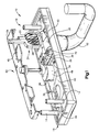
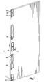
- a door lever assembly 10 for use in single (as shown in Figure 7) or double door applications includes a lever handle 12 and mounting studs 14 for a trim housing 16. Turning the lever handle 12 results in movement of a lift arm 24, which is engaged to move connected vertical rods 62 that operate retraction or extension of door latches 61.
- the lever handle 12 is of conventional design.
- the trim housing 16 can be attached to a door by engagement with mounting studs 14, which are typically threaded to allow easy screw attachment or disengagement.
- the trim housing 16 supports on its interior permanently attached weld studs 44.
- the weld studs 44 retain a plate 40 that defines therethrough two door lock apertures 38.
- a key cylinder 46 for locking the door can be attached to extend through the trim housing 16 to engage and control positioning of a blocking slide 45 of a door latch lock control assembly 60.
- the door latch lock control assembly 60 includes vertically directed rods 62 movably connected between latches 61 and lift arm 24.
- the blocking slide 45 is moved upward or downward by rotation of key cylinder 46.
- the lift arm 24 typically is constructed from a single integral piece of metal to have a flat lock engaging portion 26 and a flat spring engaging portion 28 joined by a curved intermediary portion.
- a short extension of the lift arm 24 also includes a pivot block 29.
- the lock engaging portion 26 engages the blocking slide 45 of the door latch lock control assembly when the blocking slide 45 is positioned in its locked position.
- the spring engaging portion 28 of the lift arm is conformably attached to an over-ride assembly 18 that includes and over-ride spring 20.
- the over-ride spring 20 is typically configured to have a high spring constant, and under normal operating torque is essentially inelastic. In addition, a preload of approximately 70 pounds is commonly imparted to the spring to result in an initial lever torque of about 10 foot-pounds. However, when sufficiently high forces are exerted the preload force will be overcome and the spring 20 will begin to compress.
- the exact spring material and configuration can be varied, and it is even possible to use elastomeric materials in place of coiled springs as necessary.
- the spring engaging portion 28 of the lift arm 24 is also attached to a vertically movable slider 30.
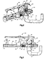
- the slider 30 is a generally flat plate that is vertically movable with the trim housing 16. Rotation of an eccentrically configured cam 42 causes a cam wing 43 to upwardly push the slider 30, which in turn upwardly impels the lift arm 24.
- the slider 30 has an attached elastomer 36 for engagement with a stop plate 34 defined by the lower edge of the plate 40.
- Use of a compressible elastomer is important for operation, since the elastomer can be slightly compressed if the cam 42 continues to rotate. This provides sufficient room for the cam wing 43 to slip underneath the slider 30, effectively disengaging the cam 42 from the slider 30.
- dual lift springs 32 are attached at opposite edges between the slider 30 and plate 40.
- the lift springs 32 are biased to normally push the slider 30 downward, which in turn acts to rotate the cam 42 and return the lever to a horizontal position.
- these lift springs 32 are ineffective if the cam 42 has been rotated to slip the cam wing 43 past the slider 30.
- the door lever handle 12 (not indicated in the Figure for clarity) can be connected by a pin (not shown) to a lever connection site 47 defined at one end of a shaft 48.
- a shear pin 49 having a plurality of flat edges 50 is attached.
- the shear pin 49 fits into a shear pin connection site 51 having matching flat edged walls 52 defined by the cam 42.
- the shear pin 49 extends outward in one direction for engagement with the cam 42. As long as torque is maintained with predefined limits, rotation of the door lever handle 12 results in rotation of the shaft 48, and consequent rotation of the shear pin connected cam 42.
- the pivot 70 is has a first lobe 72 separated from a second lobe 74 by a narrow waist 76.
- the pivot is typically constructed from a durable metal configured to withstand substantial compressive and shear forces without deformation.
- the bias of the lift springs 32 maintains the door lever handle 12 in a substantially horizontal position to allow easy grasping of the handle by a user desiring to open a door.
- the handle 12 is rotated downward, consequently rotating the shaft 48 and shear pin 49 connected cam 42. Rotation of the eccentrically configured cam 42 is converted into upward, linearly directed movement of the slider 30 as the wing 43 of the cam engages and impels the slider 30 upward against the biasing force exerted by the lift springs 32.
- Operation of the lever handle is altered when the blocking slide is moved downward into a locking position.
- the blocking slide 45 prevents upward movement of the lift arm 24. Since movement of the lift arm 24 is prevented, the pivot 70 is free to rotate, with its first lobe 72 rotating back toward the slider 30 to permit direct contact between the elastomer 36 and stop plate 34. In addition, movement of the connected slider, cam, shaft, and door lever handle is inhibited. Someone trying to open the door would realize from the resistance to movement of the door lever handle that the door is locked.
- the preload force on the over-ride spring can be overcome and the door handle will rotate to a downwardly directed position.
- the lift arm does not move upward. Instead, against increasingly greater resistance the cam 42 can be forced to rotate.
- the slider 30 moves upward, compressing the over-ride spring 20, but not causing movement of the lift arm 24.
- the elastomer 36 engages the stop plate 34.
- a pivot can be designed to be actively pulled into a new position as the lift arm retracts.
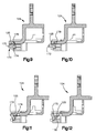
- This is illustrated in connection with Figures 9 through 12, which sequentially illustrate a lift arm 124 having a lift hook 125 that pulls pivot arm 178.
- the pivot arm 178 is integrally formed extension of a pivot 170, and as illustrated in Figures 9 to 12 is pulled by the lift hook 125 to rotate a first lobe 172 out of blocking position.
- the embodiment illustrated in these Figures 9 to 12, as well as the embodiment illustrated in Figure 8, act in substantially the same manner as that described in connection with Figures 1 to 7. The only functional difference between these embodiments is an insensitivity to gravitational direction, and improved pivoting reliability.
- all embodiments allow the normal operation and use of a door lever assembly that is substantially identical to conventional door lever assemblies when normal forces are exerted.
- the present mechanism disengages the lever from the cam by breakage of the shear pin when to prevent damage to the door lever assembly.
- the door lever assembly absorbs blows (by the over-ride spring) and then disengages to prevent damage. Because of the use of the over-ride spring and the elastomer/stop plate interaction, in single door applications there will be typically no need to rely on shear pin failure to prevent damage to the locked door lever assembly.
- shear pin failure is still needed as a last resort should excessive forces be applied to an unlocked door.
- the improved shear pin design and placement make shear pin failure both easier to rely upon and easier to replace.
Landscapes
- Engineering & Computer Science (AREA)
- Mechanical Engineering (AREA)
- Lock And Its Accessories (AREA)
Applications Claiming Priority (2)
| Application Number | Priority Date | Filing Date | Title |
|---|---|---|---|
| US173282 | 1993-12-27 | ||
| US08/173,282 US5570916A (en) | 1993-12-27 | 1993-12-27 | Breakaway lever clutch with vertical lift trim |
Publications (3)
| Publication Number | Publication Date |
|---|---|
| EP0662555A2 true EP0662555A2 (fr) | 1995-07-12 |
| EP0662555A3 EP0662555A3 (fr) | 1996-04-17 |
| EP0662555B1 EP0662555B1 (fr) | 1999-04-07 |
Family
ID=22631309
Family Applications (1)
| Application Number | Title | Priority Date | Filing Date |
|---|---|---|---|
| EP94309690A Expired - Lifetime EP0662555B1 (fr) | 1993-12-27 | 1994-12-22 | Ensemble de poignée de porte |
Country Status (5)
| Country | Link |
|---|---|
| US (1) | US5570916A (fr) |
| EP (1) | EP0662555B1 (fr) |
| CA (1) | CA2138444A1 (fr) |
| DE (1) | DE69417711T2 (fr) |
| NZ (1) | NZ270231A (fr) |
Cited By (5)
| Publication number | Priority date | Publication date | Assignee | Title |
|---|---|---|---|---|
| EP0662552A3 (fr) * | 1994-01-10 | 1996-04-17 | Von Duprin Inc | Ensemble de poignée de porte. |
| GB2325020A (en) * | 1997-05-05 | 1998-11-11 | Adams Rite Mfg | Door latch actuators with lost motion |
| EP2987928A1 (fr) * | 2014-07-24 | 2016-02-24 | ASSA ABLOY Nederland B.V. | Ensemble serrure à mortaise |
| CN111980488A (zh) * | 2020-08-11 | 2020-11-24 | 济南和知创信息科技有限公司 | 一种系统窗用执手 |
| US20240125151A1 (en) * | 2020-04-28 | 2024-04-18 | Schlage Lock Company Llc | Rotation converter |
Families Citing this family (10)
| Publication number | Priority date | Publication date | Assignee | Title |
|---|---|---|---|---|
| US6178795B1 (en) * | 2000-03-08 | 2001-01-30 | Taiwan Fu Hsing Industrial Co., Ltd. | Lockable structure for a big-handle lock |
| US6802546B2 (en) * | 2001-02-23 | 2004-10-12 | Schlage Lock Company | Convertible door lock latch mechanism |
| US6540274B2 (en) | 2001-02-23 | 2003-04-01 | Schlage Lock Company | Slide |
| US6893059B2 (en) * | 2002-11-25 | 2005-05-17 | Shen Mu-Lin | Cylindrical lock with improved resistance to torque |
| US8267440B2 (en) * | 2008-09-17 | 2012-09-18 | I-Tek Metal Mfg. Co., Ltd. | Connecting device for concealed-type top or bottom latch for panic exit door lock |
| US8011702B2 (en) * | 2008-11-04 | 2011-09-06 | I-Tek Metal Mfg. Co., Ltd. | Outer operational device for panic exit door lock |
| US8267442B2 (en) * | 2008-12-10 | 2012-09-18 | I-Tek Metal Mfg. Co., Ltd. | Outer operational device for panic exit door lock |
| US7634927B1 (en) | 2009-02-04 | 2009-12-22 | I-Tek Metal Mfg. Co., Ltd. | Panic exit door lock allowing locking on both sides |
| US8267441B2 (en) * | 2010-02-09 | 2012-09-18 | I-Tek Metal Mfg. Co., Ltd. | Operating device for lock |
| CA3183917C (fr) * | 2017-08-08 | 2025-07-08 | Schlage Lock Company Llc | Réduction et évaluation de bruit de matériel pour porte |
Family Cites Families (13)
| Publication number | Priority date | Publication date | Assignee | Title |
|---|---|---|---|---|
| US2961866A (en) * | 1958-06-18 | 1960-11-29 | Nat Lock Co | Combination screen door latch and lock assembly |
| US3545799A (en) * | 1969-12-01 | 1970-12-08 | Abraham Gertsfeld | Multiple bolt mechanism |
| US3881331A (en) * | 1973-10-02 | 1975-05-06 | Gkn Stenman Ab | Locking device incorporating a lock case, an escutcheon and a door handle |
| US3999411A (en) * | 1975-10-24 | 1976-12-28 | Folger Adam Co., Division Of Telkee, Inc. | Lock knob control mechanism |
| GB2045337B (en) * | 1979-03-23 | 1983-03-23 | Chubb & Sons Lock & Safe Co | Bolt mechanisms |
| US4321812A (en) * | 1979-12-28 | 1982-03-30 | The Eastern Company | Paddle lock with pivotally mounted handle disconnect member |
| US4520736A (en) * | 1983-05-06 | 1985-06-04 | Thomas A. James | Lightweight safe and door mechanism therefor |
| JPS6141762U (ja) * | 1984-08-21 | 1986-03-17 | 俊彦 山下 | 錠前 |
| US4754715A (en) * | 1984-12-10 | 1988-07-05 | Squires William D | Toggle-type safe door locking mechanism |
| US4982986A (en) * | 1988-12-19 | 1991-01-08 | Adams Rite Manufacturing Company | Lever/knob actuated entry mechanism |
| US5290077A (en) * | 1992-01-14 | 1994-03-01 | W&F Manufacturing, Inc. | Multipoint door lock assembly |
| US5149152A (en) * | 1992-02-06 | 1992-09-22 | Flambeau Products Corporation | Lockable latch assembly with flexible band locking member surrounding a cam surface |
| US5445423A (en) * | 1993-07-01 | 1995-08-29 | Von Duprin, Inc. | Breakaway lever clutch |
-
1993
- 1993-12-27 US US08/173,282 patent/US5570916A/en not_active Expired - Lifetime
-
1994
- 1994-12-19 CA CA002138444A patent/CA2138444A1/fr not_active Abandoned
- 1994-12-21 NZ NZ270231A patent/NZ270231A/en not_active IP Right Cessation
- 1994-12-22 DE DE69417711T patent/DE69417711T2/de not_active Expired - Fee Related
- 1994-12-22 EP EP94309690A patent/EP0662555B1/fr not_active Expired - Lifetime
Cited By (7)
| Publication number | Priority date | Publication date | Assignee | Title |
|---|---|---|---|---|
| EP0662552A3 (fr) * | 1994-01-10 | 1996-04-17 | Von Duprin Inc | Ensemble de poignée de porte. |
| GB2325020A (en) * | 1997-05-05 | 1998-11-11 | Adams Rite Mfg | Door latch actuators with lost motion |
| EP2987928A1 (fr) * | 2014-07-24 | 2016-02-24 | ASSA ABLOY Nederland B.V. | Ensemble serrure à mortaise |
| NL2013248B1 (en) * | 2014-07-24 | 2016-09-20 | Assa Abloy Nederland B V | Mortise lock assembly. |
| US20240125151A1 (en) * | 2020-04-28 | 2024-04-18 | Schlage Lock Company Llc | Rotation converter |
| US12559986B2 (en) * | 2020-04-28 | 2026-02-24 | Schlage Lock Company Llc | Rotation converter |
| CN111980488A (zh) * | 2020-08-11 | 2020-11-24 | 济南和知创信息科技有限公司 | 一种系统窗用执手 |
Also Published As
| Publication number | Publication date |
|---|---|
| US5570916A (en) | 1996-11-05 |
| EP0662555B1 (fr) | 1999-04-07 |
| NZ270231A (en) | 1996-08-27 |
| DE69417711T2 (de) | 1999-09-09 |
| CA2138444A1 (fr) | 1995-06-28 |
| DE69417711D1 (de) | 1999-05-12 |
| EP0662555A3 (fr) | 1996-04-17 |
Similar Documents
| Publication | Publication Date | Title |
|---|---|---|
| EP0633372B1 (fr) | Ensemble de poignée de porte | |
| EP0662554B1 (fr) | Ensemble de poignée de porte | |
| EP0662555B1 (fr) | Ensemble de poignée de porte | |
| US7523968B2 (en) | Reach out lock | |
| US4529234A (en) | Electrical operating means for door lock mechanisms | |
| EP1845224B1 (fr) | Verrouillage de boulon à oeil motorisé | |
| CA3074062C (fr) | Surpassement cle pour appareil de verrouillage multipoint electromecanique | |
| WO2007000763A1 (fr) | Serrure a mortaise | |
| US5564760A (en) | Door lever assembly having non-machined fastenerless trim | |
| CA3052497A1 (fr) | Ensemble verrou a pene dormant a deploiement automatique | |
| US5484179A (en) | Failsafe electric locking lever trim | |
| KR910005293B1 (ko) | 개량된 보울트 작동장치를 갖춘 래치보울트 작동 조립체 | |
| EP1495202B1 (fr) | Verrou de porte commande electriquement | |
| US6543820B2 (en) | Latching device and method | |
| US5516161A (en) | Breakaway lever clutch with cam drive pin | |
| EP4575153A1 (fr) | Verrou pour élément de fermeture coulissant et système de fermeture le comprenant | |
| AU2020204253B2 (en) | Double door lock assembly | |
| AU2019210627B1 (en) | A latch assembly | |
| EP1522662B1 (fr) | Barre de poussée anti-panique pour serrures encastrées | |
| AU5352900A (en) | A lock for a moveable wing | |
| JPS5925063B2 (ja) | ドア錠用非常開放受け金具アセンブリ |
Legal Events
| Date | Code | Title | Description |
|---|---|---|---|
| PUAI | Public reference made under article 153(3) epc to a published international application that has entered the european phase |
Free format text: ORIGINAL CODE: 0009012 |
|
| AK | Designated contracting states |
Kind code of ref document: A2 Designated state(s): DE FR GB IT |
|
| PUAL | Search report despatched |
Free format text: ORIGINAL CODE: 0009013 |
|
| AK | Designated contracting states |
Kind code of ref document: A3 Designated state(s): DE FR GB IT |
|
| 17P | Request for examination filed |
Effective date: 19961011 |
|
| 17Q | First examination report despatched |
Effective date: 19970606 |
|
| GRAG | Despatch of communication of intention to grant |
Free format text: ORIGINAL CODE: EPIDOS AGRA |
|
| GRAG | Despatch of communication of intention to grant |
Free format text: ORIGINAL CODE: EPIDOS AGRA |
|
| GRAH | Despatch of communication of intention to grant a patent |
Free format text: ORIGINAL CODE: EPIDOS IGRA |
|
| GRAH | Despatch of communication of intention to grant a patent |
Free format text: ORIGINAL CODE: EPIDOS IGRA |
|
| GRAA | (expected) grant |
Free format text: ORIGINAL CODE: 0009210 |
|
| AK | Designated contracting states |
Kind code of ref document: B1 Designated state(s): DE FR GB IT |
|
| ITF | It: translation for a ep patent filed | ||
| REF | Corresponds to: |
Ref document number: 69417711 Country of ref document: DE Date of ref document: 19990512 |
|
| ET | Fr: translation filed | ||
| PG25 | Lapsed in a contracting state [announced via postgrant information from national office to epo] |
Ref country code: GB Free format text: LAPSE BECAUSE OF NON-PAYMENT OF DUE FEES Effective date: 19991222 |
|
| PLBE | No opposition filed within time limit |
Free format text: ORIGINAL CODE: 0009261 |
|
| STAA | Information on the status of an ep patent application or granted ep patent |
Free format text: STATUS: NO OPPOSITION FILED WITHIN TIME LIMIT |
|
| 26N | No opposition filed | ||
| GBPC | Gb: european patent ceased through non-payment of renewal fee |
Effective date: 19991222 |
|
| PG25 | Lapsed in a contracting state [announced via postgrant information from national office to epo] |
Ref country code: FR Free format text: LAPSE BECAUSE OF NON-PAYMENT OF DUE FEES Effective date: 20000831 |
|
| PG25 | Lapsed in a contracting state [announced via postgrant information from national office to epo] |
Ref country code: DE Free format text: LAPSE BECAUSE OF NON-PAYMENT OF DUE FEES Effective date: 20001003 |
|
| REG | Reference to a national code |
Ref country code: FR Ref legal event code: ST |
|
| PG25 | Lapsed in a contracting state [announced via postgrant information from national office to epo] |
Ref country code: IT Free format text: LAPSE BECAUSE OF NON-PAYMENT OF DUE FEES;WARNING: LAPSES OF ITALIAN PATENTS WITH EFFECTIVE DATE BEFORE 2007 MAY HAVE OCCURRED AT ANY TIME BEFORE 2007. THE CORRECT EFFECTIVE DATE MAY BE DIFFERENT FROM THE ONE RECORDED. Effective date: 20051222 |