EP0662701A2 - Schalter mit Fähigkeit zur Bestimmung dessen Lebensende - Google Patents
Schalter mit Fähigkeit zur Bestimmung dessen Lebensende Download PDFInfo
- Publication number
- EP0662701A2 EP0662701A2 EP95300152A EP95300152A EP0662701A2 EP 0662701 A2 EP0662701 A2 EP 0662701A2 EP 95300152 A EP95300152 A EP 95300152A EP 95300152 A EP95300152 A EP 95300152A EP 0662701 A2 EP0662701 A2 EP 0662701A2
- Authority
- EP
- European Patent Office
- Prior art keywords
- switch
- count
- actuations
- elapsed time
- predetermined magnitude
- Prior art date
- Legal status (The legal status is an assumption and is not a legal conclusion. Google has not performed a legal analysis and makes no representation as to the accuracy of the status listed.)
- Granted
Links
Images


Classifications
-
- G—PHYSICS
- G08—SIGNALLING
- G08B—SIGNALLING SYSTEMS, e.g. PERSONAL CALLING SYSTEMS; ORDER TELEGRAPHS; ALARM SYSTEMS
- G08B21/00—Alarms responsive to a single specified undesired or abnormal condition and not otherwise provided for
- G08B21/18—Status alarms
- G08B21/182—Level alarms, e.g. alarms responsive to variables exceeding a threshold
-
- H—ELECTRICITY
- H01—ELECTRIC ELEMENTS
- H01H—ELECTRIC SWITCHES; RELAYS; SELECTORS; EMERGENCY PROTECTIVE DEVICES
- H01H1/00—Contacts
- H01H1/0015—Means for testing or for inspecting contacts, e.g. wear indicator
Definitions
- the present invention relates generally to a device which is able to monitor its own number of actuations and predict its own end of life and, more particularly, it relates to a limit switch which is able to count its own actuation and store the value in a way which reduces the number of lost actuations while working within the capabilities of its constituent components.
- limit switch In many applications, devices are used to control the operation of machinery, assembly lines or other types of equipment.
- a typical example of this type of device is the limit switch which is very well known to those skilled in the art.
- the limit switch In operation, the limit switch is typically located proximate the path of an object being manipulated by the equipment or, alternatively, proximate the path of a portion of the equipment. When the limit switch is actuated, it typically makes or breaks electrical power between two preselected locations.
- limit switches can be used to provide a signal to a controller that a preselected event has occurred.
- limit switches Like most mechanical devices, limit switches have a certain lifetime after which it can be expected that the switch will fail for some mechanical reason. For example, components within the limit switch can wear out due to normal frictional effects. In addition, components may fail because of repeated flexing such as when a spring is cycled. Another possible cause for a switch failure is contact erosion that occurs between a moveable contact and a stationary contact. These and other causes can lead to the failure of a switch after a certain number of operations. Empirical studies can determine the expected life of a device based on statistical information obtained from many thousands of devices.
- a means for counting the actuations of a device such as a limit switch
- the number of actuations performed during the life of the switch can then be used as a criterion for determining when the device should be replaced as part of a preventative maintenance program.
- previous attempts to monitor the number of actuations of devices have proven to be difficult and counterproductive.
- the number of operations of a limit switch can be counted by another mechanical device, but that device will also experience the normal reasons for failure, such as frictional wear. Therefore, the device used to count the operations of the limit switch may fail before the limit switch itself.
- Electronic means can be used to count the actuations of a limit switch, but this technique also exhibits certain inherent problems.
- a power failure can cause the stored information to be lost.
- the number of data storage operations is often limited to a certain maximum limit and the permitted number of storage operations may, in fact, be less than the expected lifetime of the switch that is being monitored.
- Another problem related to the monitoring of switch actuations is the costs. In some situations, the costs of monitoring the number of operations of a limit switch can exceed the costs of the switch itself and therefore make the effort counterproductive. In addition, when devices such as limit switches are monitored to maintain a count of their actuations, it is necessary to determine the number of actuations in order to decide on when preventive maintenance replacement should occur. It is sometimes difficult to determine the precise count stored in the limit switch and inform the user of the number of actuations. The replacement of the switch is sometimes less expensive than the determination of the number of counts stored at any given time.
- the present invention provides a switch characterised by: means for measuring elapsed time; means, responsive to an actuator of said switch, for recording a first counting value of the number of actuations of said switch subsequent to a preselected event; means for detecting a first occurrence of either (a) said first counting value being equal to a first predetermined magnitude or (b) a lapse of a preselected period of said elapsed time subsequent to said preselected event, whichever occurs first; means for resetting said first counting value and said elapsed time measuring means upon said first occurrence; means for adding said first counting value to a second counting value in response to said detecting means; and means for providing a signal when said second counting value exceeds a second predetermined magnitude.
- the present invention provides a means for counting the number of actuations of a device, such as a limit switch, and storing the count in a manner which is easily accessible by external equipment or by an operator.
- the present invention performs this function in a way which does not risk the loss of important stored data and does not exceed the capacity of electronic storage media used for these purposes.
- a switch, or other mechanically actuated device, made in accordance with the present invention comprises a means for measuring a preselected period of time.
- This measuring means can be a clock or other timing device that is capable of recording the duration of elapsed time between two preselected events.
- the present invention further comprises a first means for recording the count of the number of actuations of the switch during a preselected period of time.
- This first recording means can be the volatile random access memory of a microprocessor.
- the first recording means is responsive to an actuator of the switch.
- the present invention also comprises a second means for recording the occurrence when the recorded count is equal to a predetermined magnitude. In addition, the second recording means also monitors the passage of a preselected period of time.
- the second recording means can react to the count equaling or exceeding 250 actuations.
- the second recording means can also react to the passage of a preselected period of time.
- the programmable period may be equal to one hour since the preceding occurrence of either the lapse of the period of time or the count being equal to the predetermined magnitude of actuations.
- the second recording means could be initiated in response to a power failure. In operation, this second recording means could be nonvolatile memory and would store the count currently maintained by the first recording means when the count reaches a predetermined number, such as 256. Even if the count in the first storing means does not reach the magnitude of 256, the second recording means would react to the passage of eight hours if that occurred first.
- the second recording means also comprises a means for resetting the count and the clock upon the first occurrence.
- the present invention also comprises a means for counting the number of the first occurrences described above.
- it comprises a means for comparing the number of first occurrences to a predetermined programmable value. For example, if the number of first occurrences represents a total number of actuations that equals 20 million, the comparison by the comparing means would compare the value that represents the 20 million actuations to a predetermined value that represents the expected lifetime of the switch.
- the present invention comprises a means for providing a signal when the number of first occurrences exceeds the predetermined value. When this occurs, it is assumed that the switch has been actuated, either actually or effectively a sufficient number of times for the switch to be replaced in anticipation of its end of life.
- the limit switch Upon the exceedance of the predetermined value by the number of stored occurrences, several actions can be taken.
- One action would be for the limit switch to provide an operator detectable signal, such as a flashing light emitting diode.
- Another action could involve the transmission of a signal onto a signal bus for receipt by a central controller.
- the flashing light emitting diode is especially advantageous in situations where the limit switch is a stand alone application.
- the communication to a central controller would be most appropriate in a situation in which the limit switch is connected to a signal bus for coordinated operation with a plurality of other switches.
- FIG 1 illustrates a device, such as a limit switch, which is provided with the ability to monitor its usage and determine the imminence of its own end of life.
- the device 10 comprises a clock 12 which serves as a means for measuring a preselected period of time.
- the clock as is well known to those skilled in the art, can comprise a crystal oscillator or other means for measuring elapsed time.
- One embodiment of the present invention utilizes a Controller Area Network (CAN), such as that developed by Robert Bosch GmbH and commercially available from Motorola, Inc., which comprises a microprocessor. This is shown schematically in Figure 1 as a CAN integrated circuit 14.
- the microprocessor capability of the CAN integrated circuit 14 allows it to function as a temporary data storage apparatus that is responsive to an actuator of the device 10.
- the actuator is schematically illustrated as the switch 16.
- the first recording means which is the microprocessor of the CAN integrated circuit 14, is responsive to the switch 16 and serves as the first means for recording the count of the number of actuations of the switch 16 during a preselected period of time that is measured by the clock 12.
- the microprocessor portion 50 (shown in Figure 4) of the CAN integrated circuit 14 provides a second means for recording the first occurrence of the count, described above, being equal to a predetermined magnitude.
- the microprocessor maintains a count which is incremented each time the switch 16 is actuated. It also stores a reference magnitude with which the increasing count can be compared.
- the microprocessor reacts to this occurrence by storing a value in the nonvolatile random access memory (NOVRAM) 18.
- NOVRAM nonvolatile random access memory
- the value stored in the nonvolatile random access memory unit 18 can be incremented upon the occurrence of either of two alternative events, whichever occurs first.
- the first event is the number of actuations of switch 16 being equal to a predetermined threshold magnitude stored in the volatile memory of a CAN integrated circuit microprocessor.
- the second event is the passage of a predetermined period of time measured by the clock 12. The first of these two events to occur will result in the microprocessor in the CAN integrated circuit recording the first occurrence in the nonvolatile memory unit 18.
- the microprocessor 50 of the present invention is also used as a means for comparing the number of first occurrences, which are stored in the nonvolatile memory unit, with a predetermined programmable reference value stored in the nonvolatile memory unit. This is also stored in the NOVRAM and is programmable by the user. When the number of occurrences stored in the nonvolatile memory is equal to the predetermined reference value, this is indicative that the switch has experienced a sufficient number of actuations to conclude that it has reached its predicted time for replacement.
- nonvolatile random access memory unit 18 have a limited number of writes to their memory that can be executed without exceeding the capability of the memory device.
- one type of nonvolatile random access memory is specified to be able to experience over 100 thousand write cycles at a minimum.
- One problem that occurs is that the expected life of the switch 16, measured in actuations, greatly exceeds the permissible number of write cycles of the nonvolatile random access memory unit 18.
- the microprocessor 50 of the CAN integrated circuit 14 is provided with volatile memory that is capable of operating to maintain the count of a very high number of switch actuations, the volatility of its memory limits its usefulness for the purpose of storing the very large number necessary to maintain an ongoing count of the total actuations experienced by the switch 16.
- the present invention advantageously combines the attributes of the volatile memory 52 associated with the microprocessor 50 in the CAN integrated circuit 14 and the nonvolatile memory provided by the random access memory unit 18.
- Figure 1 also shows a regulator 20 which is used to provide regulated power to the CAN integrated circuit, the clock 12 and the nonvolatile random access memory unit 18.
- the communication circuit 22 permits the CAN integrated circuit 14 to communicate with a bus 26.
- the bus 26 is illustrated schematically in Figure 1 to represent any means for transmitting signals between the device 10 and other devices that are also connected to the bus 26.
- One possible bus configuration is the sensor actuator bus which is described in United States Patent Application Serial No. 07/993,831 and United States Patent Application Serial No. 07/993,180 that were filed on 18 December 1992 by Hans Sitte and assigned Honeywell Inc. However, it should be understood that other types of buses can be used in association with the present invention.
- the present invention can be utilized in a stand alone application without being connected to a bus.
- the communication circuit 22 is used to transmit the information stored in the nonvolatile random access memory unit 18 to the bus according to the proper protocol as determined by the CAN integrated circuit's microprocessor 50.
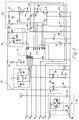
- Figure 2 illustrates a more detailed version of the circuit that is schematically shown in Figure 1.
- the type or value of the component shown in Figure 1 are identified in Table I shown below.
- Circuit P7 is maintained at a regulated 5 volts by the regulator 20.
- Circuit point P6 is connected to a normally open contact of a switch and a circuit point P5 is connected to the normally closed contact of the switch.
- Circuit point P4 is connected to the communication line (low) and circuit point P3 is connected to the communication line (high).
- Circuit point P2 is connected to a nine to twenty-five volt source and circuit P1 is an electrical ground.
- connection points P6 and P5 permit the microprocessor 50 to monitor the actuations of an associated switch, such as a limit switch.
- the microprocessor 50 continually monitors contacts P6 and P5 and also monitors an input provided by the clock 12. If either of two predefined events occur, the occurrence is recorded in the nonvolatile random access memory unit 18. The first event is a predetermined number of actuations of the associated switch.
- the microprocessor 50 can be programmed to recognize the occurrence of 256 actuations of the switch and, in response to this occurrence, change the count stored by the random access memory 52.
- the microprocessor 50 can also be programmed to monitor the lapse of time measured by the clock 12.
- the microprocessor can react to that passage of time regardless of the number of switch actuations that have occurred since the preceding change of the count stored by the nonvolatile memory.
- the microprocessor changes the count stored by the nonvolatile random access memory unit 18 and clears both the clock count and the switch actuation count. This begins a new cycle during which the microprocessor 50 will again monitor the number of switch actuations and the passage of time to determine if either of the two events occurs.
- the time limit used by the microprocessor to monitor the passage of time measured by the clock 12 and the actuation limit used by the microprocessor to monitor the number of actuations that have occurred with respect to the switch 16 should be chosen wisely to make sure that the number of actuations used as a threshold by the microprocessor 50 is approximately the number of actuations expected during the time period used by the microprocessor to monitor the clock. A significant mismatch between these two values will result in an inefficient usage of the present invention.
- the nonvolatile memory in conjunction with the microprocessor can record 25 million actuations of the switch 16 without exceeding the capabilities of the nonvolatile random access memory unit 18.
- the preselected time period chosen for comparison to the clock by the microprocessor is once each hour, the number of write operations allowed to a typical nonvolatile random access memory 18 will permit the system shown in Figure 1 to operate for over 11 years without exceeding the capabilities of the nonvolatile random access memory unit 18
- the present invention When the microprocessor, in association with the nonvolatile random access memory, determines that the switch is approaching its expected end of life, the present invention is equipped to notify either an operator or a remote controller of this situation.
- the communication circuit 22 transmits either a warning signal or the accumulated count stored by the nonvolatile memory 18, or another appropriate signal, to the remote controller so that the controller can be alerted that the end of life of the device is approaching.
- the present invention is associated with a switch that is not connected to a bus 26, alternative means can be used to notify an operator of this occurrence.
- Figure 3 is an exemplary illustration of a limit switch 30 that has an actuator arm 32 that is intended to pivot about a center of rotation 36 as illustrated by arrows A and B.
- Each actuation of the arm 32 can be sensed by the microprocessor contained within the body of the switch.
- circuit points P6 and P5 can be connected to the mechanical actuator within the switch which is used to change the electrical connection of the switch.
- two light emitting diodes are provided.
- a first light emitting diode 40 represents the connection of electrical power to the switch. In other words, when the switch and its internal components are provided with electrical power from an external source, light emitting diode 40 is energized.
- Light emitting diode 44 represents the actuation status of the switch.
- light emitting diode 44 can be energized when a normally opened switch is closed or when a normally closed switch is opened.
- the number of total actuations represented by the value stored in the nonvolatile random access memory unit 18 exceeds a predicted end of life threshold for the limit switch, one of the two light emitting diodes, 40 or 44, can be alternatively energized and de-energized to attract the attention of an operator.
- light emitting diode 40 is intermittently energized and de-energized for this purpose while the light emitting diode 44 is used in its traditional manner to illustrate the actuation of the switch.
- Figure 4 shows a particular configuration of the CAN integrated circuit 14 shown in Figure 2.
- the schematic representation in Figure 4 represents the particular CAN integrated circuit 14 that is available in commercial quantities from Motorola Inc. and identified by number MC68HC05X4.
- the central processing unit 50 cooperates with the volatile random access memory 52 to provide the first means for recording the count of the number of actuations of the switch during the preselected period of time described above.
- the configuration shown in Figure 4 is utilized for many other purposes that relate to the connection of the limit switch to a sensor bus.
- the presence of a microprocessor 50 within the CAN integrated circuit 14 facilitates the implementation of the first storing means.
- the present invention solves a perplexing problem relating to the monitoring of the end of life for a switch or similar mechanical actuated device. It combines the reliability and power fail resilience of a nonvolatile random access memory with the virtually limitless number of storage cycles capable through the use of a microprocessor having volatile memory even though memory is subject to data loss in the event of a power failure. By selectively combining these two types of storage media along with the logical procedure of monitoring both time and switch actuations by the microprocessor.
- One of the advantages of the dual logical monitoring procedure performed on the microprocessor is that it avoids several problems that could otherwise occur.
- the present invention provides a means for measuring a large number of cycles of a switch in a manner which increases the likelihood of maintaining an accurate count regardless of the likelihood of power failures, the number of actuations expected per unit of time and the particular application in which the switch is used.
- the circuit shown in Figure 2 can be provided with a power fail routine that responds to a loss of power and saves the contents of the volatile memory in the event that the microprocessor 14 is deprived of power.
- the present invention serves another useful purpose. If a number of limit switches are employed in association with a single piece of machinery or a single assembly line, and one of the limit switches in the system must be replaced because of a failure or because its predicted time for replacement has elapsed, the present invention permits each of the limit switches to be examined to determine if they are approaching their end of life but have not yet reached it. If this is the case, those aging limit switches can be replaced while the machine or assembly line is shut down instead of waiting for their predicted time for replacement to occur in the near future. This reduces downtime significantly.
Landscapes
- Business, Economics & Management (AREA)
- Emergency Management (AREA)
- Physics & Mathematics (AREA)
- General Physics & Mathematics (AREA)
- Measurement Of Unknown Time Intervals (AREA)
Applications Claiming Priority (2)
| Application Number | Priority Date | Filing Date | Title |
|---|---|---|---|
| US08/179,857 US5420571A (en) | 1994-01-11 | 1994-01-11 | Switch with end of life prediction capability |
| US179857 | 1994-01-11 |
Publications (3)
| Publication Number | Publication Date |
|---|---|
| EP0662701A2 true EP0662701A2 (de) | 1995-07-12 |
| EP0662701A3 EP0662701A3 (de) | 1996-10-30 |
| EP0662701B1 EP0662701B1 (de) | 1999-10-27 |
Family
ID=22658271
Family Applications (1)
| Application Number | Title | Priority Date | Filing Date |
|---|---|---|---|
| EP95300152A Expired - Lifetime EP0662701B1 (de) | 1994-01-11 | 1995-01-11 | Schalter mit Fähigkeit zur Bestimmung dessen Lebensende |
Country Status (3)
| Country | Link |
|---|---|
| US (1) | US5420571A (de) |
| EP (1) | EP0662701B1 (de) |
| DE (1) | DE69512943T2 (de) |
Families Citing this family (30)
| Publication number | Priority date | Publication date | Assignee | Title |
|---|---|---|---|---|
| CN1088197C (zh) * | 1994-10-27 | 2002-07-24 | 西门子公司 | 开关器 |
| US5671161A (en) * | 1995-12-19 | 1997-09-23 | Honeywell Inc. | Switch with diagnostic capability |
| US5754451A (en) * | 1996-02-29 | 1998-05-19 | Raytheon Company | Preventative maintenance and diagonstic system |
| US5941370A (en) | 1996-09-10 | 1999-08-24 | Nichols; Bruce W. | Electrical contact wear |
| US5911081A (en) * | 1997-05-05 | 1999-06-08 | Sun Microsystems, Inc. | Method and apparatus for selectively inhibiting power shutdowns based upon the number of power shutdowns that an electrical device has been experienced |
| US6957172B2 (en) | 2000-03-09 | 2005-10-18 | Smartsignal Corporation | Complex signal decomposition and modeling |
| ES2320095T3 (es) | 2000-03-09 | 2009-05-19 | Smartsignal Corporation | Operador generalizado de similitud angular lenticular. |
| US7739096B2 (en) * | 2000-03-09 | 2010-06-15 | Smartsignal Corporation | System for extraction of representative data for training of adaptive process monitoring equipment |
| US6952662B2 (en) * | 2000-03-30 | 2005-10-04 | Smartsignal Corporation | Signal differentiation system using improved non-linear operator |
| AUPR187800A0 (en) | 2000-12-04 | 2001-01-04 | Electrical & Instrumentation Services Australia Pty Ltd | Circuit monitoring device |
| US7233886B2 (en) * | 2001-01-19 | 2007-06-19 | Smartsignal Corporation | Adaptive modeling of changed states in predictive condition monitoring |
| US20020183971A1 (en) * | 2001-04-10 | 2002-12-05 | Wegerich Stephan W. | Diagnostic systems and methods for predictive condition monitoring |
| US7539597B2 (en) | 2001-04-10 | 2009-05-26 | Smartsignal Corporation | Diagnostic systems and methods for predictive condition monitoring |
| US6975962B2 (en) * | 2001-06-11 | 2005-12-13 | Smartsignal Corporation | Residual signal alert generation for condition monitoring using approximated SPRT distribution |
| US7287177B2 (en) * | 2003-12-04 | 2007-10-23 | International Business Machines Corporation | Digital reliability monitor having autonomic repair and notification capability |
| US20050144524A1 (en) * | 2003-12-04 | 2005-06-30 | International Business Machines Corporation | Digital reliability monitor having autonomic repair and notification capability |
| CN1716306B (zh) * | 2004-07-02 | 2010-05-05 | 鸿富锦精密工业(深圳)有限公司 | 工治具管控系统及方法 |
| US8275577B2 (en) | 2006-09-19 | 2012-09-25 | Smartsignal Corporation | Kernel-based method for detecting boiler tube leaks |
| US8311774B2 (en) | 2006-12-15 | 2012-11-13 | Smartsignal Corporation | Robust distance measures for on-line monitoring |
| US20080183404A1 (en) * | 2007-01-13 | 2008-07-31 | Arsalan Alan Emami | Monitoring heater condition to predict or detect failure of a heating element |
| GB0801704D0 (en) * | 2008-01-31 | 2008-03-05 | Eja Ltd | Safety switch |
| EP2169700B1 (de) * | 2008-09-26 | 2011-11-09 | Siemens Aktiengesellschaft | Verfahren und Vorrichtung zur Überwachung eines Schaltvorganges und Relaisbaugruppe |
| DE202009014066U1 (de) * | 2009-10-16 | 2011-03-03 | Liebherr-Werk Ehingen Gmbh | Hubendschalter und Hebevorrichtung |
| DE102010041998A1 (de) * | 2010-10-05 | 2012-04-05 | Robert Bosch Gmbh | Verfahren zur Vorhersage der Einsatzfähigkeit eines Relais oder eines Schützes |
| JP4784701B1 (ja) * | 2010-12-03 | 2011-10-05 | オムロン株式会社 | スイッチ |
| US9988239B2 (en) | 2013-03-22 | 2018-06-05 | Otis Elevator Company | Preventative maintenance by detecting number of switching events of components |
| TWI634447B (zh) | 2016-12-30 | 2018-09-01 | 財團法人工業技術研究院 | 加熱元件的狀態診斷與評估方法及其應用 |
| US10763659B2 (en) | 2019-01-29 | 2020-09-01 | Arc Suppression Technologies | Power contact fault clearing device |
| KR102464669B1 (ko) | 2019-01-29 | 2022-11-10 | 아크 서프레션 테크놀로지스 | 고속 아크 억제기 |
| KR20220106741A (ko) | 2019-09-11 | 2022-07-29 | 아크 서프레션 테크놀로지스 | 전력 콘택 전극 표면 플라즈마 요법 |
Family Cites Families (7)
| Publication number | Priority date | Publication date | Assignee | Title |
|---|---|---|---|---|
| US4163360A (en) * | 1975-04-08 | 1979-08-07 | Kabushiki Kaisha Daini Seikosha | Timer device |
| US4598248A (en) * | 1984-04-12 | 1986-07-01 | General Electric Company | Test operation of electronic demand register |
| US4742476A (en) * | 1986-01-27 | 1988-05-03 | General Motors Corporation | Automatic engine oil change indicator system |
| US4992777A (en) * | 1987-08-10 | 1991-02-12 | Omron Tateisi Electronics Co. | Switch device with a trouble detecting and indicating function |
| DE3802497A1 (de) * | 1988-01-28 | 1989-08-03 | Licentia Gmbh | Benutzungsfuehrungsanzeige fuer leistungsschalter |
| JPH01263662A (ja) * | 1988-04-15 | 1989-10-20 | Fuji Xerox Co Ltd | 記録装置およびその消耗部品 |
| JPH0276427U (de) * | 1988-08-11 | 1990-06-12 |
-
1994
- 1994-01-11 US US08/179,857 patent/US5420571A/en not_active Expired - Lifetime
-
1995
- 1995-01-11 DE DE69512943T patent/DE69512943T2/de not_active Expired - Fee Related
- 1995-01-11 EP EP95300152A patent/EP0662701B1/de not_active Expired - Lifetime
Also Published As
| Publication number | Publication date |
|---|---|
| US5420571A (en) | 1995-05-30 |
| DE69512943D1 (de) | 1999-12-02 |
| EP0662701A3 (de) | 1996-10-30 |
| DE69512943T2 (de) | 2000-02-24 |
| EP0662701B1 (de) | 1999-10-27 |
Similar Documents
| Publication | Publication Date | Title |
|---|---|---|
| EP0662701A2 (de) | Schalter mit Fähigkeit zur Bestimmung dessen Lebensende | |
| US6795941B2 (en) | Method for diagnosing a network | |
| EP0904573B1 (de) | Verfahren zur überwachung des zustands eines regelventils sowie ventilvorrichtung | |
| US20050075817A1 (en) | Functional test apparatus for a field device, a method for functional testing of a field device, and a field device | |
| US6986075B2 (en) | Storage-device activation control for a high-availability storage system | |
| US8271141B2 (en) | Control valve system with cycle monitoring, diagnostics and degradation prediction | |
| US7369339B2 (en) | Failure prediction method for magnetic disk devices, and a magnetic disk device using the same | |
| EP2118544B1 (de) | Flüssigkeitsregelungssystem und verfahren | |
| KR19990068893A (ko) | 중앙집중 관리가 가능한 윤활유 자동 공급 시스템 | |
| KR102171954B1 (ko) | 로봇 제어 장치 및 이 제어 장치를 구비한 로봇 | |
| EP0193732A1 (de) | Überwachungs- und Kontrolleinrichtung für Schaltgeräte und Schaltgerätekombinationen | |
| WO2014149054A1 (en) | Preventative maintenance by detecting lifetime of components | |
| US12241935B2 (en) | Redundant contactors with data-based preventive maintenance replacement indicators | |
| US20190286090A1 (en) | Intelligent Power Distribution Management System and Method Of Use | |
| US7631204B2 (en) | Power supply device having communication channels with different types of communication connections | |
| US3918043A (en) | Power supply monitor | |
| EP4309201B1 (de) | Zusatzgerät für einen schutzschalter, mit leistungsdiagnose | |
| US10436843B2 (en) | Programmable current sink for contact input circuits | |
| CN112286713B (zh) | 一种提高整机设备故障定位效率的复位检测电路 | |
| JPH102449A (ja) | バルブ用アクチュエータの動作監視装置 | |
| US20070085872A1 (en) | Printer and method of recording a low voltage error log | |
| CN113939888A (zh) | 预测初级继电器故障的方法 | |
| JP2008216115A (ja) | アブソリュートエンコーダ | |
| CN110994537A (zh) | 一种真空断路器智能控制系统 | |
| JPH04155544A (ja) | ログ処理方式 |
Legal Events
| Date | Code | Title | Description |
|---|---|---|---|
| PUAI | Public reference made under article 153(3) epc to a published international application that has entered the european phase |
Free format text: ORIGINAL CODE: 0009012 |
|
| AK | Designated contracting states |
Kind code of ref document: A2 Designated state(s): DE GB |
|
| PUAL | Search report despatched |
Free format text: ORIGINAL CODE: 0009013 |
|
| AK | Designated contracting states |
Kind code of ref document: A3 Designated state(s): DE GB |
|
| 17P | Request for examination filed |
Effective date: 19961220 |
|
| 17Q | First examination report despatched |
Effective date: 19970423 |
|
| GRAG | Despatch of communication of intention to grant |
Free format text: ORIGINAL CODE: EPIDOS AGRA |
|
| GRAG | Despatch of communication of intention to grant |
Free format text: ORIGINAL CODE: EPIDOS AGRA |
|
| GRAH | Despatch of communication of intention to grant a patent |
Free format text: ORIGINAL CODE: EPIDOS IGRA |
|
| GRAG | Despatch of communication of intention to grant |
Free format text: ORIGINAL CODE: EPIDOS AGRA |
|
| GRAH | Despatch of communication of intention to grant a patent |
Free format text: ORIGINAL CODE: EPIDOS IGRA |
|
| GRAH | Despatch of communication of intention to grant a patent |
Free format text: ORIGINAL CODE: EPIDOS IGRA |
|
| GRAA | (expected) grant |
Free format text: ORIGINAL CODE: 0009210 |
|
| AK | Designated contracting states |
Kind code of ref document: B1 Designated state(s): DE GB |
|
| REF | Corresponds to: |
Ref document number: 69512943 Country of ref document: DE Date of ref document: 19991202 |
|
| PLBE | No opposition filed within time limit |
Free format text: ORIGINAL CODE: 0009261 |
|
| STAA | Information on the status of an ep patent application or granted ep patent |
Free format text: STATUS: NO OPPOSITION FILED WITHIN TIME LIMIT |
|
| 26N | No opposition filed | ||
| PGFP | Annual fee paid to national office [announced via postgrant information from national office to epo] |
Ref country code: GB Payment date: 20011214 Year of fee payment: 8 |
|
| REG | Reference to a national code |
Ref country code: GB Ref legal event code: IF02 |
|
| PGFP | Annual fee paid to national office [announced via postgrant information from national office to epo] |
Ref country code: DE Payment date: 20020131 Year of fee payment: 8 |
|
| PG25 | Lapsed in a contracting state [announced via postgrant information from national office to epo] |
Ref country code: GB Free format text: LAPSE BECAUSE OF NON-PAYMENT OF DUE FEES Effective date: 20030111 |
|
| PG25 | Lapsed in a contracting state [announced via postgrant information from national office to epo] |
Ref country code: DE Free format text: LAPSE BECAUSE OF NON-PAYMENT OF DUE FEES Effective date: 20030801 |
|
| GBPC | Gb: european patent ceased through non-payment of renewal fee |