EP0663127B1 - Verteilte gemeinsame hausinterne anlage, die mehreren fernsprechanbietern erlaubt den gleichen teilnehmer zu bedienen - Google Patents
Verteilte gemeinsame hausinterne anlage, die mehreren fernsprechanbietern erlaubt den gleichen teilnehmer zu bedienen Download PDFInfo
- Publication number
- EP0663127B1 EP0663127B1 EP93921641A EP93921641A EP0663127B1 EP 0663127 B1 EP0663127 B1 EP 0663127B1 EP 93921641 A EP93921641 A EP 93921641A EP 93921641 A EP93921641 A EP 93921641A EP 0663127 B1 EP0663127 B1 EP 0663127B1
- Authority
- EP
- European Patent Office
- Prior art keywords
- telephone
- house
- wiring circuit
- carrier
- secondary carrier
- Prior art date
- Legal status (The legal status is an assumption and is not a legal conclusion. Google has not performed a legal analysis and makes no representation as to the accuracy of the status listed.)
- Expired - Lifetime
Links
- 239000000969 carrier Substances 0.000 title abstract description 20
- 230000004044 response Effects 0.000 claims abstract description 5
- 230000005540 biological transmission Effects 0.000 claims description 9
- 230000006854 communication Effects 0.000 claims description 4
- 238000004891 communication Methods 0.000 claims description 4
- 230000009977 dual effect Effects 0.000 claims description 3
- 230000004913 activation Effects 0.000 claims description 2
- 230000002860 competitive effect Effects 0.000 claims 1
- 238000005516 engineering process Methods 0.000 description 5
- 230000008859 change Effects 0.000 description 4
- 230000011664 signaling Effects 0.000 description 4
- 238000010586 diagram Methods 0.000 description 2
- 230000003993 interaction Effects 0.000 description 2
- 230000004048 modification Effects 0.000 description 2
- 238000012986 modification Methods 0.000 description 2
- 238000001228 spectrum Methods 0.000 description 2
- XUIMIQQOPSSXEZ-UHFFFAOYSA-N Silicon Chemical compound [Si] XUIMIQQOPSSXEZ-UHFFFAOYSA-N 0.000 description 1
- 230000007175 bidirectional communication Effects 0.000 description 1
- 230000001413 cellular effect Effects 0.000 description 1
- 230000003750 conditioning effect Effects 0.000 description 1
- 230000001276 controlling effect Effects 0.000 description 1
- 230000002074 deregulated effect Effects 0.000 description 1
- 230000003831 deregulation Effects 0.000 description 1
- 239000000835 fiber Substances 0.000 description 1
- 230000000977 initiatory effect Effects 0.000 description 1
- 230000007246 mechanism Effects 0.000 description 1
- 238000012544 monitoring process Methods 0.000 description 1
- 229910052710 silicon Inorganic materials 0.000 description 1
- 239000010703 silicon Substances 0.000 description 1
- 230000001960 triggered effect Effects 0.000 description 1
- 238000011144 upstream manufacturing Methods 0.000 description 1
Images

Classifications
-
- H—ELECTRICITY
- H04—ELECTRIC COMMUNICATION TECHNIQUE
- H04M—TELEPHONIC COMMUNICATION
- H04M1/00—Substation equipment, e.g. for use by subscribers
- H04M1/71—Substation extension arrangements
- H04M1/715—Substation extension arrangements using two or more extensions per line
-
- H—ELECTRICITY
- H04—ELECTRIC COMMUNICATION TECHNIQUE
- H04Q—SELECTING
- H04Q3/00—Selecting arrangements
- H04Q3/58—Arrangements providing connection between main exchange and sub-exchange or satellite
- H04Q3/62—Arrangements providing connection between main exchange and sub-exchange or satellite for connecting to private branch exchanges
- H04Q3/625—Arrangements in the private branch exchange
Definitions
- the present invention relates to equipment that allows two or more competing alternative telephone carriers to serve the same customer using the customer's existing in-house telephone wiring without interference from one telephone carrier's system to the other's.
- the present invention provides such a system.
- Service is normally provided by a primary carrier that serves on a default basis.
- a telephone user dialing a prefix code selects the carrier to be used.
- Switching arrangements insure that one and only one carrier is connected to the user's telephone wiring at any one time. Incoming calls from multiple independent carriers can be answered using the existing in-house wired telephones without modification.
- Figure 1 is a block diagram of the overall connections between the carriers and the inter-structure wiring.
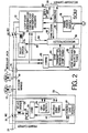
- FIG. 2 is a block diagram showing details of the implementation of the Primary Carrier Interface Unit (PCIU) and the Secondary Carrier Interface Unit (SCIU) modules of the present invention.
- PCIU Primary Carrier Interface Unit
- SCIU Secondary Carrier Interface Unit
- the present invention is made possible by alternative telephone technologies that are becoming available which do not require new wiring.
- One of these advances is short range cordless telephones that can be interfaced with a cable TV system serving as a bi-directional transmission path.
- Such technology allows the creation of an alternative telephone carrier that bypasses the current local exchange system, without the past necessity for new wires to the home.
- the present invention provides the necessary hardware to make multiple use of existing telephone wiring within a structure to allow two or more different alternative telephone systems to coexist without the need to rewire each structure since telephone equipment and wiring within the house are considered the property of the home owner.
- a telephone central office supplies operating power for the individual telephone instruments, as well as, monitoring current flow to determine when a telephone is off-hook, providing a dial tone and a high voltage ringing signal to inform the user of an incoming call.
- An alternative carrier will also have to provide such capabilities as well.
- the present invention allows the customer a choice of competing telephone systems while using the same telephone and telecommunication instruments connected to the same telephone wiring within the structure. In providing that choice to the consumer the present invention also prevents undesirable interactions from taking place between the two or more telephone systems.
- a first module is placed at the first, or primary carrier's, demarcation block, and a second module is placed at each of the secondary carriers' demarcation blocks.
- the "demarcation block” is the boundary between a telephone company's wiring and the customer's owned “in-house” on premises wiring and customer provided equipment (CPE).
- CPE customer provided equipment
- Telephone service is currently supplied by a single carrier, and for purposes of discussion in this specification that service will be referred to as being supplied by the "primary telephone carrier".
- the primary telephone carrier is initially assumed to be of the twisted-copper-wire-to-the-central-office type.
- the new carrier, or carriers, which the present invention will support are each assumed to use a cable TV system as a bi-directional transmission path and for purposes of discussion here is called the "secondary carrier". More than one secondary carrier could be supported, but for clarity of discussion, only one primary and one secondary carrier is described here in detail.
- PCIU 22 is mounted at the demarcation line between the primary carrier lines 24 to provide an interface between those lines and the customer's in-house wiring 10.
- SCIU 26 is mounted at the point of demarcation line between the secondary carrier lines 28 and the customer's in-house wiring 10.
- the secondary carrier demarcation point occurs at a modular telephone jack at a TV set top converter unit connected to the cable TV drop cable, which serves as part of the secondary carrier's transmission path.
- the secondary carrier Interface Unit (SCIU) 26 could be contained within the cable TV set top unit.
- FIG 2 illustrates the internal components of both PCIU 22 and SCIU 26. Since it is necessary to prevent interference between carriers it is necessary that one, and only one, carrier be connected to in-house wiring 10 at any one time. To accomplish this, each of PCIU and SCIU include relay switches 30 and 50, respectively. In Figure 2, PCIU switches 30 are shown as normally closed and SCIU switches 50 are shown as normally open. As will be described below, when the subscriber selects to be connected to the secondary carrier, switches 30 are remotely opened before switches 50 are remotely closed. The break-before-make configuration is necessary to insure that both carriers are not connected to the in-house wiring at the same time thus preventing the shorting out of the voltage level provided by the primary carrier.
- the preselected subscriber entered signals for selecting the use of the secondary carrier might be #8 entered via the keypad of one of telephone sets 12-20. If there are additional secondary carriers available to the subscriber they might be selected by entry of #7, or perhaps #81, or other combination not normally encountered as a present valid dialing combination.
- Code #9 might be used to connect the primary carrier to the in-house wiring 10. However, as will be discussed below the primary carrier will normally be connected to in-house wiring 10 whenever the system is in the standby mode or when the subscriber is using the primary carrier, the subscriber will not have to enter that code to connect in-house wiring 10 to the primary carrier.
- PCIU 22 Any of the codes that are discussed above that are transmitted via in-house wiring 10 will be received by PCIU 22 and to one or more SCIUs 26 that are connected to in-house wiring 10. Thus, as described above, PCIU 22 will open relay switches 30 when it receives a code for any of the secondary carriers.
- the primary carrier is generally the normal Public Switched Telephone System (PSTN). As such, the primary carrier provides a dc operating voltage plus high voltage ringing signals.
- PSTN Public Switched Telephone System
- the primary carrier provides a dc operating voltage plus high voltage ringing signals.
- PCIU 22 is shown with a power line module 44 that is connected to primary carrier telephone lines 24 to generate the necessary voltage levels to power the other components of PCIU 22.
- PCIU 22 The purpose of PCIU 22 is to control relay switches 30 so that they are open only when the subscriber is connected to a secondary carrier.
- a relay coil 32 for controlling the opening and closing of switch contacts 30 under the control of relay driver 34.
- a DTMF (dual tone multiple frequency) detector 42 e.g. Silicon Systems DTMF Receiver SS157T202
- a DTMF unit is shown in use here.
- the system of the present invention could also be implemented using the earlier pulse technology or by placing a pulse detector in parallel with the DTMF detector to interface with the older equipment as well.
- the signals received by DTMF detector 42 are decoded and presented to a logic device 36 as standard logic type signals.
- a coded pattern signal received from DTMF detector 42 processed by logic device 36 operates power relay driver 34 to cause switch contacts 30 to change position. This coded pattern causes the disconnection of the primary carrier from in-house wiring 10.
- the end of a telephone call via the secondary carrier is detected by off-hook detector 35, which causes the reconnection of the primary carrier to in-house wiring 10.
- signaling means other than DTMF could be used in this application with similar results.
- SCIU 26 is shown connected to in-house wiring 10 by means of a modular jack 74, which is internally connected directly to one side of switches 50.
- SCIU 26 could be part of a set-top cable TV unit that is connected to the incoming cable from the cable service. That cable has the capacity to handle bi-directional communications using one part of the cable's. spectrum for upstream telephone signals and the remainder of the spectrum for downstream transmission for both TV signals and telephone signals on suitable carriers (not shown).
- SCIU 26 interfaces to the secondary carrier 28 via a TV set-top unit (not shown) to the TV cable system.
- a second cable which is a standard telephone type cable, is connected between modular jack 74 on the TV set-top unit and a telephone jack in an interior wall of the structure in the same way as one would connect an extension telephone today.
- SCIU 26 includes a mains driven power supply 76 that is connected to the subscriber's electrical utility power line.
- an integrated circuit chip 72 Connected on the other side of switches 50 from modular jack 74 is an integrated circuit chip 72 to provide the functionality needed to support the PSTN telephone sets 12-20.
- This chip could be implemented by a Texas Instruments Subscriber Line Control Circuits chip TCM4204A (a complete description of the features and operation of that chip is available in Texas Instruments Telecommunications Circuit Data Book, Linear Products, 1991, pp. 4-107 to 4-131).
- the SLCC chip 72 provides the necessary services to support telephone off-hook supervision, electronic hybrid function, signal conditioning, over-voltage protection, battery feed, and ringing control.
- the secondary carrier can be provided either as a "two-wire” or a "four-wire” connection in which the sending and receiving paths share the same wires.
- the "four wire" configuration will be used (as shown in Fig. 2) with the received and transmitted signals being carried by lines 82 and 84, respectively, between the secondary carrier lines 28 and SLCC chip 72.
- those signals are converted bi-directionally by an internal electronic hybrid to interface with the two wire in-house wiring 10 for use with existing telephone sets 12-20.
- Ringing initiation can be sent ⁇ received on either the receive/transmit pair 82-84, or on separate ringing signal and signaling lines 80 and 86 via microcontroller 56 and lines 96 and 94, respectively, which are connected between microcontroller 56 and SLCC chip 72, On these lines a coded pattern corresponding to the desired ringing signal is transmitted.
- SLCC chip 72 is the conduit between the secondary carrier and the in-house wiring 10 for in-coming and out-going telephone calls.
- the secondary carrier is connected to the in-house wiring 10 only under two conditions. One, when an in-coming call is being received from the secondary carrier and the in-house wiring 10 is not already busy with another call from the primary carrier or any other carrier, and two, when the subscriber elects to make an out-going call on the secondary carrier.
- SCIU 26 checks for an off-hook condition.
- the in-house wiring 10 line voltage drops from the normal 48 volts when the receiver is on-hook to only a few volts.
- SLCC chip 72 is connected to the extension of the in-house wiring 10 between modular jack 74 and switches 50 to allow a supervisory connection within SLCC chip 72 to monitor the voltage level on in-house wiring 10 and to sense the low voltage off-hook condition.
- SLCC chip 72 in response, generates an off-hook signal which is delivered to microcontroller 56 via line 94 to prevent microcontroller 56 from sending a relay activation signal to relay driver 54 on line 98 to change the state of switches 50 as long as the off-hook condition exists unless the subscriber has also selected the secondary carrier.
- hybrid 62 Also connected to the extension of in-house wiring 10 within SCIU 26 between modular jack 74 and switches 50 is a bi-directional hybrid 62.
- hybrid 62 In communication with hybrid 62 are two other modules, a DTMF receiver 68 to monitor subscriber entered codes via one of telephone sets 12-20 and hybrid 62, and a DTMF generator 64 for generating tones to be placed on in-house wiring 10 via hybrid 62 and modular jack 74 to be sent to PCIU 22.
- DTMF receiver 68 monitors the touch-tone signals on in-house wiring 10 in the same way that DTMF receiver 42 in PCIU 22 does and then converts those signals to logic signals that microcontroller 56 can use. For example, when the touch-tone signal on in-house wiring 10 entered by the subscriber is the code to select the primary carrier (this could happen however, as stated above, connection to the primary carrier is the normal condition and it should not be necessary for the subscriber to make that selection), or a different secondary carrier, microcontroller 56 will send a signal to relay driver 54 to open switches 50.
- microcontroller 56 is programmed to recognize the code that corresponds to the secondary carrier to which it is connected. Once that recognition is registered, microcontroller 56 awaits an off-hook signal on line 94 from SLCC chip 72 before instructing relay driver 54 to close switches 50. An off-hook signal is detected by SLCC chip 72 here after PCIU 22 causes switches 30 to open. More specifically, before switches 30 open, the voltage level on in-house wiring 10 by virtue of its connection to the primary carrier is approximately 48 volts, and after switches 30 open, in-house wiring 10 is not connected to any voltage source and is in essence floating with no current flowing. The absence of a current flow results in SLCC chip 72 reading the voltage level on in-house wiring 10 as zero, thus assuming that there is an off-hook condition.
- Microcontroller 56 first triggers DTMF generator 64 to generate the tone that the subscriber would enter to select the secondary carrier to which SCIU 26 is connected. That tone is then applied to in-house wiring 10 via hybrid 62 and modular jack 74 so that it can be detected by DTMF receiver 42 of PCIU 22 so that it will open switches 50 as if the subscriber had entered the code for the secondary carrier. Switches 30 are then opened and switches 50 are closed by the same mechanism that was described above when the subscriber entered the appropriate code for the secondary carrier.
- SCIU 26 easily lends itself to this technology.
- packetized signals received on line 80 can be depacketized by microcontroller 56 for use on in-house wiring 10 by the conventional telephone sets 12-20, or signals to be transmitted on the secondary carrier can be packetized by microcontroller 56 prior to being placed on out-going line 86.
Landscapes
- Engineering & Computer Science (AREA)
- Physics & Mathematics (AREA)
- Astronomy & Astrophysics (AREA)
- General Physics & Mathematics (AREA)
- Computer Networks & Wireless Communication (AREA)
- Signal Processing (AREA)
- Telephonic Communication Services (AREA)
- Sub-Exchange Stations And Push- Button Telephones (AREA)
Claims (8)
- Räumlichkeiten-internes Telefonverbindungssystem mit Wettbewerbs-Zugang, um es einem Telefonbenutzer zu ermöglichen, eine einzelne Räumlichkeiten-interne Telefonverkabelung (10) wahlweise mit einem primären Träger (24) und einem sekundären Träger (28) zu verbinden, wobei die Telefonapparate (12-20) des Telefonbenutzers und die Fernmeldeausstattung mit der einzelnen Räumlichkeiten-internen Telefonverkabelung (10) verbunden sind, wobei dieses System umfasst:eine erste fernbediente Schalteinheit mit einem ersten Schalter (30), der zwischen der einzelnen Räumlichkeiten-internen Telefonverkabelung (10) und dem primären Träger (24) angeschlossen ist, wobei der erste Schalter (30) normalerweise geschlossen ist, und wobei der erste Schalter zum wahlweisen Unterbrechen und Verbinden der einzelnen Räumlichkeiten-internen Telefonverkabelung (10) von und mit dem primären Träger (24) in den Räumlichkeiten des Telefonbenutzers dient;eine zweite fernbediente Schalteinheit mit einem zweiten Schalter (50), der zwischen der einzelnen Räumlichkeiten-internen Telefonverkabelung (10) und dem sekundären Träger (28) angeschlossen ist, wobei der zweite Schalter normalerweise offen ist, und wobei der zweite Schalter (50) zum wahlweisen Verbinden und Unterbrechen der einzelnen Räumlichkeiten-internen Telefonverkabelung (10) mit und von dem sekundären Träger (28) in den Räumlichkeiten des Telefonbenutzers dient;einen an die erste Schalteinheit und zweite Schalteinheit gekoppelter Betätigungscontroller, um individuell die Aktivierung der ersten Schalteinheit und zweiten Schalteinheit zu kontrollieren, und somit auch die entsprechenden Schalter, um die einzelne Räumlichkeiten-interne Telefonverkabelung (10) mit entweder dem primären Träger (24) oder den sekundären Träger (28) in Antwort auf eine Trägerauswahl durch den Telefonbenutzer zu verbinden oder zu unterbrechen; undein Paar jeweils an die erste beziehungsweise zweite Schalteinheit gekoppelter Verriegelungen, wobei jede der Verriegelungen des Paars an den Betätigungscontroller gekoppelt ist und unter dessen Kontrolle steht, um das Schließen des jeweils offenen ersten oder zweiten Schalters zu verhindern, bevor der jeweils geschlossene erste oder zweite Schalter geöffnet wird, um eine Verbindung des primären Trägers (24) und des sekundären Trägers (28) miteinander durch die einzelne Räumlichkeiten-interne Telefonverkabelung (10) zu verhindern.
- System gemäß Anspruch 1, ferner umfassend einen an die einzelne Räumlichkeiten-interne Telefonverkabelung (10) und den Betätigungscontroller gekoppelten Dekodierer, wobei der Dekodierer dazu dient, dem Betätigungscontroller zu signalisieren, die jeweils entsprechende erste oder zweite Schalteinheit zu betätigen, um den von dem Telefonbenutzer wahlweise ausgewählten primären Träger (24) oder sekundären Träger (28) mit der einzelnen Räumlichkeiten-internen Telefonverkabelung (10) durch den jeweils entsprechenden ersten und zweiten Schalter zu verbinden, in Antwort auf einen vorher ausgewählten Code eines Satzes an elektronisch übertragenen Codes, die Signalen entsprechen, die der Telefonbenutzer durch einen der Telefonapparate (12-20) und andere Fernmeldeausstattungen gestartet hat, die mit der einzelnen Räumlichkeiten-internen Telefonverkabelung (10) verbundenen sind, wobei ein Code dazu dient, den primären Träger (24) zu kennzeichnen und ein anderer Code dazu dient, den sekundären Träger (28) zu kennzeichnen.
- System gemäß Anspruch 1:wobei die zweite Schalteinheit ferner einen dritten Schalter enthält, der normalerweise offen ist; undwobei das System ferner ein Leistungsversorgungsteilsystem umfasst, um Klingelsignale und Telefonbetriebsspannungen zu erzeugen und das, wenn der zweite Schalter geschlossen ist, die einzelne Räumlichkeiten-interne Telefonverkabelung (10) mit dem zweiten Träger (28) verbindend;wobei der dritte Schalter zwischen der einzelnen Räumlichkeiten-internen Telefonverkabelung (10) und dem Leistungsversorgungsteilsystem angeschlossen ist.
- System gemäß Anspruch 1, ferner umfassend:einen mit der einzelnen Räumlichkeiten-internen Telefonverkabelung (10) und dem Betätigungscontroller verbundener Belegungsdetektor (35), um ein Belegungszeichen zu erzeugen, sobald einer der Standardtelefonapparate (12-20) oder andere Fernmeldeausstattungen, die mit der einzelnen Räumlichkeiten-internen Telefonverkabelung (10) verbunden ist, belegt ist;wobei der Betätigungscontroller, nachdem er ein Belegungszeichen erhalten hat und ein Telefonbenutzer den vorher ausgewählten Code zur Auswahl des sekundären Trägers (28) eingegeben hat, die erste und zweite fernbediente Schalteinheit aktiviert, um den primären Träger (24) von der einzelnen Räumlichkeiten-internen Telefonverkabelung (10) zu trennen und den sekundären Träger (28) mit der einzelnen Räumlichkeiten-internen Telefonverkabelung (10) zu verbinden.
- System gemäß Anspruch 1, ferner umfassend:eine Telefonvermittlungsklinke (74), die so angeordnet ist, dass sie mit der einzelnen Räumlichkeiten-internen Telefonverkabelung (10) verbunden ist; undein Standardtelefonkabel, welches zwischen der Telefonvermittlungsklinke (74) und dem zweiten Schalter (50) der zweiten fernbedienten Schalteinheit in einer Innenwand innerhalb eines Gebäudes des Teilnehmers verläuft.
- System gemäß Anspruch 4, wobei der Betätigungscontroller einen Zweiton-Mehrfrequenzsignaldetektor umfasst, der mit der einzelnen Räumlichkeiten-internen Telefonverkabelung (10) verbunden ist, um Zweiton-Mehrfrequenzsignale zu erkennen, die durch einen der Standardtelefonapperate (12-20) und andere Fernmeldeausstattungen erzeugt wird, wenn der Telefonbenutzer die Standardtelefonapperate und andere Fernmeldeausstattungen dazu veranlasst, ein vorher ausgewähltes Codesignal erzeugt, um den sekundären Träger (28) auszuwählen, damit er mit der einzelnen Räumlichkeiten-internen Telefonverkabelung (10) verbunden wird.
- System gemäß Anspruch 1, ferner umfassend einen zwischen dem zweiten Schalter (50) der zweiten fernbedienten Schalteinheit und dem sekundären Träger (28) verbundenen Paketierer, um Signale umzuwandeln, die durch an die einzelne Räumlichkeiten-interne Telefonverkabelung (10) angeschlossene Standardtelefonapperate (12-20) und andere Fernmeldeausstattungen erzeugt wurden, in Antwort auf die Teilnehmereingabe von Telefonnummern und anderen Signalen, deren Erzeugung durch die an der einzelnen Räumlichkeiten-internen Telefonverkabelung (10) angeschlossene Standardtelefonapparate (12-20) und andere Fernmeldeausstattungen durch den Teilnehmer verursacht wurde, um die Signale für die Übertragung zu dem sekundären Träger (28) zu paketieren, wenn der sekundäre Träger an die einzelne Räumlichkeiten-interne Telefonverkabelung (10) angeschlossen ist.
- System gemäß Anspruch 1, wobei:der primäre Träger (24) über eine körperliche Telefon-Amtsleitung übermittelt wird, die Spannungspegel und Klingelsignale bereitstellt; undein sekundärer Träger (28) über ein bidirektionales Fernsehkabelsystem übermittelt wird.
Applications Claiming Priority (3)
| Application Number | Priority Date | Filing Date | Title |
|---|---|---|---|
| US949424 | 1992-09-22 | ||
| US07/949,424 US5341415A (en) | 1992-09-22 | 1992-09-22 | Method and apparatus for sharing of common in-house wiring to permit multiple telephone carriers to serve the same customer |
| PCT/US1993/008778 WO1994007321A1 (en) | 1992-09-22 | 1993-09-16 | Shared common in-house wiring to permit multiple telephone carriers to serve the same customer |
Publications (3)
| Publication Number | Publication Date |
|---|---|
| EP0663127A1 EP0663127A1 (de) | 1995-07-19 |
| EP0663127A4 EP0663127A4 (de) | 1995-09-27 |
| EP0663127B1 true EP0663127B1 (de) | 2001-12-12 |
Family
ID=25489063
Family Applications (1)
| Application Number | Title | Priority Date | Filing Date |
|---|---|---|---|
| EP93921641A Expired - Lifetime EP0663127B1 (de) | 1992-09-22 | 1993-09-16 | Verteilte gemeinsame hausinterne anlage, die mehreren fernsprechanbietern erlaubt den gleichen teilnehmer zu bedienen |
Country Status (5)
| Country | Link |
|---|---|
| US (1) | US5341415A (de) |
| EP (1) | EP0663127B1 (de) |
| CA (1) | CA2144954A1 (de) |
| DE (1) | DE69331328T2 (de) |
| WO (1) | WO1994007321A1 (de) |
Families Citing this family (55)
| Publication number | Priority date | Publication date | Assignee | Title |
|---|---|---|---|---|
| US6310940B1 (en) * | 1966-12-16 | 2001-10-30 | Ncr Corporation | Personal computer interactive phone system |
| US5550915A (en) * | 1993-07-02 | 1996-08-27 | Lucent Technologies, Inc. | Apparatus for use in completing telephone calls |
| US5550912A (en) * | 1994-02-28 | 1996-08-27 | At&T Corp. | Connections between a toll network and multiple local networks |
| US5475749A (en) * | 1994-02-28 | 1995-12-12 | At&T Corp. | Connections between a toll network and multiple local networks |
| US5715296A (en) * | 1994-09-20 | 1998-02-03 | Telular Corp. | Concurrent wireless/landline interface apparatus |
| US5661792A (en) * | 1994-10-18 | 1997-08-26 | At&T | Completing telecommunications calls in a competitive local and toll enviroment |
| US5633917A (en) * | 1994-11-18 | 1997-05-27 | Rogers; Laurence S. | Remote-control telephone answering system and method |
| US5579377A (en) * | 1994-11-18 | 1996-11-26 | Rogers; Laurence S. | Remote-control telephone answering system and method |
| US5563938A (en) * | 1995-04-07 | 1996-10-08 | Teltone Corporation | Subscriber telephone diverter switch |
| GB2300089A (en) * | 1995-04-21 | 1996-10-23 | Eurotel Telecom Limited | Least cost router in a telecommunications system |
| US5903643A (en) * | 1995-06-02 | 1999-05-11 | Teleport Communications Group, Inc. | Multi-line station interface |
| US5991388A (en) * | 1995-06-30 | 1999-11-23 | Siemens Information And Communication Networks, Inc. | Method and system for routing calls to a party |
| US6009160A (en) * | 1995-06-30 | 1999-12-28 | Siemens Information And Communication Networks, Inc. | Method for routing a call |
| US5978464A (en) * | 1995-06-30 | 1999-11-02 | Siemens Information And Communications Networks, Inc. | Method for updating a local switch internal database in system having different service providers within a common numbering plan area |
| US5887056A (en) * | 1995-06-30 | 1999-03-23 | Siemens Information And Communication Networks | Method for routing telephone calls to subscribers of different service providers within a common numbering plan area |
| US5748724A (en) * | 1995-06-30 | 1998-05-05 | Siemens Stomberg-Carlson | Method for transferring a subscriber to a new local service provider |
| US5970131A (en) * | 1995-06-30 | 1999-10-19 | Siemens Information And Communication Networks, Inc. | Method for providing location/geographic portability in a system having different service providers within a common numbering plan area |
| US5859895A (en) * | 1995-12-07 | 1999-01-12 | Bell Atlantic Network Services, Inc. | Auxiliary circuit switching for provisioning and/or repair in a fiber-to-the-curb system |
| US6002502A (en) * | 1995-12-07 | 1999-12-14 | Bell Atlantic Network Services, Inc. | Switchable optical network unit |
| AU1748997A (en) * | 1996-01-17 | 1997-08-11 | Jim Rautio | Method and apparatus for routing a dialed telephone number |
| US5983098A (en) * | 1996-05-31 | 1999-11-09 | Lucent Technologies Inc. | Dual-mode network access point |
| US6028923A (en) * | 1996-07-15 | 2000-02-22 | Call Director, Inc. | Telecommunications enhancement user interface system and method |
| US6167120A (en) * | 1996-11-06 | 2000-12-26 | Lextron Systems, Inc. | Apparatus and methods for home networking |
| US5937055A (en) * | 1997-01-28 | 1999-08-10 | Lucent Technologies Inc. | Method and apparatus for routing telephone calls between alternate telephone service providers |
| US5887054A (en) * | 1997-02-28 | 1999-03-23 | Lucent Technologies Inc. | Play and plug telephone system |
| US5883944A (en) * | 1997-02-28 | 1999-03-16 | Lucent Technologies Inc. | "Plug and play" telephone system |
| US5999612A (en) * | 1997-05-27 | 1999-12-07 | International Business Machines Corporation | Integrated telephony and data services over cable networks |
| US6061450A (en) * | 1997-06-17 | 2000-05-09 | Bauer; William Dean | Alternate telephone system |
| US6137877A (en) * | 1997-07-09 | 2000-10-24 | Robin; Bruce | Method and apparatus for routing a dialed telephone number |
| US6282277B1 (en) * | 1997-11-28 | 2001-08-28 | Avaya Technology Corp. | Unbundling device and method for connecting a competing local exchange carrier (CLEC) to the subscriber loop of a local exchange carrier (LEC) |
| GB2335335A (en) * | 1998-03-13 | 1999-09-15 | Northern Telecom Ltd | Carrying speech-band signals over power lines |
| US6160880A (en) * | 1998-04-02 | 2000-12-12 | Bell Atlantic Network Services, Inc. | Local number portability service saver |
| US6480510B1 (en) | 1998-07-28 | 2002-11-12 | Serconet Ltd. | Local area network of serial intelligent cells |
| US6956826B1 (en) | 1999-07-07 | 2005-10-18 | Serconet Ltd. | Local area network for distributing data communication, sensing and control signals |
| US6690677B1 (en) | 1999-07-20 | 2004-02-10 | Serconet Ltd. | Network for telephony and data communication |
| US6891944B1 (en) * | 1999-09-10 | 2005-05-10 | David Matthew Smith | System and method of autodialing for long-distance access |
| US6549616B1 (en) | 2000-03-20 | 2003-04-15 | Serconet Ltd. | Telephone outlet for implementing a local area network over telephone lines and a local area network using such outlets |
| IL135744A (en) | 2000-04-18 | 2008-08-07 | Mosaid Technologies Inc | Telephone communication system over a single telephone line |
| US6842459B1 (en) | 2000-04-19 | 2005-01-11 | Serconet Ltd. | Network combining wired and non-wired segments |
| US20020162116A1 (en) * | 2001-04-27 | 2002-10-31 | Sony Corporation | VoIP telephony peripheral |
| IL144158A (en) | 2001-07-05 | 2011-06-30 | Mosaid Technologies Inc | Socket for connecting an analog telephone to a digital communications network that carries digital voice signals |
| JP2003046642A (ja) * | 2001-08-01 | 2003-02-14 | Nec Corp | 回線接続制御装置 |
| IL161190A0 (en) | 2001-10-11 | 2004-08-31 | Serconet Ltd | Outlet with analog signal adapter, method for use thereof and a network using said outlet |
| US7315615B2 (en) * | 2002-01-25 | 2008-01-01 | Sittelle Technologies, Inc. | Automatic telephone line switch |
| US20030194077A1 (en) * | 2002-04-15 | 2003-10-16 | Blaine Edward Ramey | Bridge between multiple telephone service providers |
| DE60231384D1 (de) * | 2002-07-05 | 2009-04-16 | Hewlett Packard Co | Verbesserungen für DTMF Signalisierung |
| IL152824A (en) | 2002-11-13 | 2012-05-31 | Mosaid Technologies Inc | A socket that can be connected to and the network that uses it |
| IL154234A (en) | 2003-01-30 | 2010-12-30 | Mosaid Technologies Inc | Method and system for providing dc power on local telephone lines |
| IL154921A (en) | 2003-03-13 | 2011-02-28 | Mosaid Technologies Inc | A telephone system that includes many separate sources and accessories for it |
| IL157787A (en) | 2003-09-07 | 2010-12-30 | Mosaid Technologies Inc | Modular outlet for data communications network |
| US20050074110A1 (en) * | 2003-10-02 | 2005-04-07 | Moreman Charles S. | Remote local number portability switchover |
| IL159838A0 (en) | 2004-01-13 | 2004-06-20 | Yehuda Binder | Information device |
| IL160417A (en) | 2004-02-16 | 2011-04-28 | Mosaid Technologies Inc | Unit added to the outlet |
| US7873058B2 (en) | 2004-11-08 | 2011-01-18 | Mosaid Technologies Incorporated | Outlet with analog signal adapter, a method for use thereof and a network using said outlet |
| IL210169A0 (en) | 2010-12-22 | 2011-03-31 | Yehuda Binder | System and method for routing-based internet security |
Family Cites Families (66)
| Publication number | Priority date | Publication date | Assignee | Title |
|---|---|---|---|---|
| US2957047A (en) * | 1958-12-05 | 1960-10-18 | Bell Telephone Labor Inc | Automatic telephone system |
| JPS51115718A (en) * | 1975-02-24 | 1976-10-12 | Pioneer Electronic Corp | Bi-directional catv system |
| US4191860A (en) * | 1978-07-13 | 1980-03-04 | Bell Telephone Laboratories, Incorporated | Data base communication call processing method |
| US4860379A (en) * | 1979-05-18 | 1989-08-22 | General Instrument Corporation | Data communications system |
| DE2932701C2 (de) * | 1979-08-11 | 1982-06-09 | Licentia Patent-Verwaltungs-Gmbh, 6000 Frankfurt | Verfahren für eine Datenübertragung nach dem Prinzip der Zeitmultiplexübertragung |
| CA1158738A (en) * | 1980-04-30 | 1983-12-13 | Manitoba Telephone System (The) | Video and data distribution module with subscriber terminal |
| US4410765A (en) * | 1981-06-04 | 1983-10-18 | United Networks, Inc. | Telephone call routing and charging system |
| US4404514A (en) * | 1981-08-24 | 1983-09-13 | General Instrument Corporation | Fault detection system as for locating faulty connections in a cable television system |
| US4521881A (en) * | 1981-11-02 | 1985-06-04 | Wang Laboratories, Inc. | Data communication system with increased effective bandwidth |
| DE3207022C2 (de) * | 1982-02-26 | 1986-09-04 | Siemens AG, 1000 Berlin und 8000 München | Informationsabruf-System für Text-, Graphik-, Ton-, Standbild- und Film-Information |
| US4533948A (en) * | 1982-04-30 | 1985-08-06 | General Instrument Corporation | CATV Communication system |
| US4768188A (en) * | 1982-05-20 | 1988-08-30 | Hughes Network Systems, Inc. | Optical demand assigned local loop communication system |
| US4534024A (en) * | 1982-12-02 | 1985-08-06 | At&T Bell Laboratories | System and method for controlling a multiple access data communications system including both data packets and voice packets being communicated over a cable television system |
| US4633462A (en) * | 1983-07-18 | 1986-12-30 | The Board Of Trustees Of The University Of Illinois | Multiple access communication on a CATV reverse channel |
| US4530008A (en) * | 1983-10-03 | 1985-07-16 | Broadband Technologies, Inc. | Secured communications system |
| CA1251838A (en) * | 1984-04-04 | 1989-03-28 | Yukitsuna Furuya | Packet transmission system |
| US4717970A (en) * | 1984-06-21 | 1988-01-05 | Zenith Electronics Corporation | Video system with programmable VCR |
| US4577312A (en) * | 1984-07-05 | 1986-03-18 | At&T Bell Laboratories | Arrangement for wideband transmission via a switched network |
| GB8417910D0 (en) * | 1984-07-13 | 1984-08-15 | British Telecomm | Communications network |
| US4771425A (en) * | 1984-10-29 | 1988-09-13 | Stratacom, Inc. | Synchoronous packet voice/data communication system |
| US4819228A (en) * | 1984-10-29 | 1989-04-04 | Stratacom Inc. | Synchronous packet voice/data communication system |
| US4903261A (en) * | 1984-10-29 | 1990-02-20 | Stratacom, Inc. | Synchronous packet voice/data communication system |
| DE3586758T2 (de) * | 1985-04-30 | 1993-04-22 | Ibm | Modem zur steuerung eines modemnetzes. |
| DE3527329A1 (de) * | 1985-07-31 | 1987-02-05 | Philips Patentverwaltung | Digitales funkuebertragungssystem mit variabler zeitschlitzdauer der zeitschlitze im zeitmultiplexrahmen |
| US4698841A (en) * | 1985-08-02 | 1987-10-06 | Gte Laboratories, Incorporated | Methods of establishing and terminating connections in a distributed-control burst switching communications system |
| CA1263721A (en) * | 1985-10-18 | 1989-12-05 | Owen Lloyd Nelson | Communication system for the transfer of small digital message blocks and large digital message blocks |
| US4763317A (en) * | 1985-12-13 | 1988-08-09 | American Telephone And Telegraph Company, At&T Bell Laboratories | Digital communication network architecture for providing universal information services |
| US4689619A (en) * | 1985-12-26 | 1987-08-25 | General Instrument Corporation | Method and apparatus for polling subscriber terminals |
| DE3607682A1 (de) * | 1986-03-08 | 1987-09-24 | Telefonbau & Normalzeit Gmbh | Fernsprechreihenanlage |
| JPH063927B2 (ja) * | 1987-04-10 | 1994-01-12 | 富士通株式会社 | 最適化ブロツクポ−リング方式 |
| US4829297A (en) * | 1987-05-08 | 1989-05-09 | Allen-Bradley Company, Inc. | Communication network polling technique |
| US4797879A (en) * | 1987-06-05 | 1989-01-10 | American Telephone And Telegraph Company At&T Bell Laboratories | Packet switched interconnection protocols for a star configured optical lan |
| US4887290A (en) * | 1987-08-05 | 1989-12-12 | Norbert W. Zawacki | Cellular alarm backup system |
| CA1317667C (en) * | 1987-11-02 | 1993-05-11 | Michel Dufresne | Catv subscriber terminal transmission control |
| US4837800A (en) * | 1988-03-18 | 1989-06-06 | Motorola, Inc. | Cellular data telephone system and cellular data telephone therefor |
| US5029163A (en) * | 1988-03-18 | 1991-07-02 | At&T Bell Laboratories | Synchronous protocol data formatter |
| CA1327238C (en) * | 1988-04-21 | 1994-02-22 | Michel Dufresne | Catv network with filters |
| US4959862A (en) * | 1988-04-28 | 1990-09-25 | Catel Telecommunications, Inc. | Active multichannel video processing hub for optimum transition from fiber to coax |
| US4998247A (en) * | 1988-06-10 | 1991-03-05 | Irvine Halliday David | Active star-configured local area network |
| FR2634608B1 (fr) * | 1988-07-22 | 1994-05-06 | Etat Francais Cnet | Reseau domotique cable multipoints reconfigurable de distribution simultanee et/ou alternative de plusieurs types de signaux, notamment de signaux d'images en bande de base, et procede de configuration d'un tel reseau |
| DE68928867T2 (de) * | 1988-07-22 | 1999-04-29 | Hitachi Ltd | ATM-Vermittlungssystem |
| US5012469A (en) * | 1988-07-29 | 1991-04-30 | Karamvir Sardana | Adaptive hybrid multiple access protocols |
| US4866763A (en) * | 1988-08-17 | 1989-09-12 | American Telephone And Telegraph Company, At&T Bell Laboratories | Interexchange carrier automatic route selection system |
| US4901340A (en) * | 1988-09-19 | 1990-02-13 | Gte Mobilnet Incorporated | System for the extended provision of cellular mobile radiotelephone service |
| US4991206A (en) * | 1988-09-30 | 1991-02-05 | Electroline Equipment Inc. | Method and apparatus for jamming selected television programs |
| GB2223378B (en) * | 1988-09-30 | 1992-12-16 | Stc Plc | Automatic telecommunications systems |
| US4991172A (en) * | 1988-10-28 | 1991-02-05 | International Business Machines Corporation | Design of a high speed packet switching node |
| US4980886A (en) * | 1988-11-03 | 1990-12-25 | Sprint International Communications Corporation | Communication system utilizing dynamically slotted information |
| US4972505A (en) * | 1988-12-06 | 1990-11-20 | Isberg Reuben A | Tunnel distributed cable antenna system with signal top coupling approximately same radiated energy |
| JPH0748739B2 (ja) * | 1988-12-09 | 1995-05-24 | 富士通株式会社 | 多重アクセス制御方法および該方法を実施する多重アクセス制御システム |
| US5016245A (en) * | 1988-12-23 | 1991-05-14 | Siemens Aktiengesellschaft | Modular expandable digital single-stage switching network in ATM (Asynchronous Transfer Mode) technology for a fast packet-switched transmission of information |
| NL8900269A (nl) * | 1989-02-03 | 1990-09-03 | Nederland Ptt | Methode voor het via een meervoud van asynchroon tijdverdeelde transmissiekanalen overdragen van een stroom van datacellen, waarbij per transmissiekanaal een tellerstand wordt bijgehouden, die afhankelijk is van het aantal datacellen per tijd. |
| US4970717A (en) * | 1989-02-23 | 1990-11-13 | At&T Bell Laboratories | Photonic local/metropolitan area network |
| US5124980A (en) * | 1989-03-20 | 1992-06-23 | Maki Gerald G | Synchronous multiport digital 2-way communications network using T1 PCM on a CATV cable |
| JP2964151B2 (ja) * | 1989-07-03 | 1999-10-18 | 富士通株式会社 | 通信制御方式 |
| US4949395A (en) * | 1989-07-07 | 1990-08-14 | Telefonaktiebolaget L M Ericsson | Method and arrangement for dynamically allocating time slots to connections in a digital mobile radio system |
| US4961188A (en) * | 1989-09-07 | 1990-10-02 | Bell Communications Research, Inc. | Synchronous frequency encoding technique for clock timing recovery in a broadband network |
| US5001707A (en) * | 1989-11-02 | 1991-03-19 | Northern Telecom Limited | Method of providing reserved bandwidth in a dual bus system |
| US4980907A (en) * | 1989-12-15 | 1990-12-25 | Telefonaktiebolaget L M Ericsson | Telecommunication combination comprising a telepoint and a portable radio terminal |
| US5048081A (en) * | 1989-12-28 | 1991-09-10 | At&T Bell Laboratories | Arrangement for routing packetized messages |
| EP0462540B1 (de) * | 1990-06-18 | 2000-08-30 | Fujitsu Limited | System zur Zurückschaltung für ein ATM-Netzwerk |
| US5111454A (en) * | 1990-08-16 | 1992-05-05 | Motorola, Inc. | Digital cellular tdm system employing 6:1 packing of transcoded information |
| US5115431A (en) * | 1990-09-28 | 1992-05-19 | Stratacom, Inc. | Method and apparatus for packet communications signaling |
| US5138649A (en) * | 1990-11-16 | 1992-08-11 | General Instrument Corporation | Portable telephone handset with remote control |
| US5161154A (en) * | 1991-02-12 | 1992-11-03 | Motorola, Inc. | Communication system having a varied communication resource grant channel usage requirement |
| GB2257870B (en) * | 1991-07-18 | 1995-06-14 | Jeffrey Wilson | Telecommunications service network |
-
1992
- 1992-09-22 US US07/949,424 patent/US5341415A/en not_active Expired - Lifetime
-
1993
- 1993-09-16 EP EP93921641A patent/EP0663127B1/de not_active Expired - Lifetime
- 1993-09-16 WO PCT/US1993/008778 patent/WO1994007321A1/en not_active Ceased
- 1993-09-16 DE DE69331328T patent/DE69331328T2/de not_active Expired - Fee Related
- 1993-09-16 CA CA002144954A patent/CA2144954A1/en not_active Abandoned
Also Published As
| Publication number | Publication date |
|---|---|
| DE69331328D1 (de) | 2002-01-24 |
| US5341415A (en) | 1994-08-23 |
| EP0663127A1 (de) | 1995-07-19 |
| CA2144954A1 (en) | 1994-03-31 |
| WO1994007321A1 (en) | 1994-03-31 |
| EP0663127A4 (de) | 1995-09-27 |
| DE69331328T2 (de) | 2002-08-14 |
Similar Documents
| Publication | Publication Date | Title |
|---|---|---|
| US5341415A (en) | Method and apparatus for sharing of common in-house wiring to permit multiple telephone carriers to serve the same customer | |
| US5903643A (en) | Multi-line station interface | |
| KR100831484B1 (ko) | 단일 전화 회선 상의 전화 통신 시스템 | |
| KR0135508B1 (ko) | 전화 교환 시스템과, 데이터 액세스 장치로부터 고객 구내 장치를 액세스 하는 방법 | |
| US7359702B2 (en) | Apparatus for providing a gateway between a wired telephone and a wireless telephone network | |
| US6400803B1 (en) | Voice over digital subscriber line call redirection for lifeline service | |
| US5563938A (en) | Subscriber telephone diverter switch | |
| AU707903B2 (en) | Least cost router | |
| KR920002965B1 (ko) | 복수 통화회선 어댑터장치 | |
| EP0684722B1 (de) | Umlenkschnittstelle zwischen zwei Fernsprechleitungen und einer Fernsprechstelle | |
| US5369691A (en) | Telephonic information communication method and apparatus | |
| US5467386A (en) | Method for signalling/communication within an entrance telephone system and an entrance telephone system communicating according to the method | |
| US6477248B1 (en) | Multi-line station interface | |
| CN1200217A (zh) | 电信转换开关 | |
| KR101380764B1 (ko) | 중앙 전화 교환국에 연결되지 않은 가정용 폰 배선에 플러그된 폰에 폰 서비스를 제공하는 디바이스 | |
| US6658096B2 (en) | Local loop interceder | |
| US4572928A (en) | Key telephone system | |
| US6614802B1 (en) | Telecommunication network with remotely controllable, line multi-interface and telecommunication method | |
| EP0630542A1 (de) | Hybridfaser im fernsprechteilnehmerleitungssystem | |
| US5991386A (en) | Method and arrangement for the connection of multiple terminals to one subscriber line of the telephone network, and a terminal | |
| US20070223669A1 (en) | Method and apparatus for alternatively switching between phone service lines | |
| US20030091174A1 (en) | Phone your own home from within | |
| GB2100957A (en) | Call diverter | |
| KR0135491B1 (ko) | 전화 교환 시스템과, 데이타 액세스 장치로부터 고객 구내 장치를 액세스하는 방법. | |
| JP3073777B2 (ja) | 家庭用電話交換システム |
Legal Events
| Date | Code | Title | Description |
|---|---|---|---|
| PUAI | Public reference made under article 153(3) epc to a published international application that has entered the european phase |
Free format text: ORIGINAL CODE: 0009012 |
|
| 17P | Request for examination filed |
Effective date: 19950418 |
|
| AK | Designated contracting states |
Kind code of ref document: A1 Designated state(s): DE FR GB |
|
| A4 | Supplementary search report drawn up and despatched |
Effective date: 19950808 |
|
| AK | Designated contracting states |
Kind code of ref document: A4 Designated state(s): DE FR GB |
|
| GRAG | Despatch of communication of intention to grant |
Free format text: ORIGINAL CODE: EPIDOS AGRA |
|
| 17Q | First examination report despatched |
Effective date: 20000829 |
|
| GRAG | Despatch of communication of intention to grant |
Free format text: ORIGINAL CODE: EPIDOS AGRA |
|
| GRAH | Despatch of communication of intention to grant a patent |
Free format text: ORIGINAL CODE: EPIDOS IGRA |
|
| GRAH | Despatch of communication of intention to grant a patent |
Free format text: ORIGINAL CODE: EPIDOS IGRA |
|
| GRAA | (expected) grant |
Free format text: ORIGINAL CODE: 0009210 |
|
| AK | Designated contracting states |
Kind code of ref document: B1 Designated state(s): DE FR GB |
|
| REG | Reference to a national code |
Ref country code: GB Ref legal event code: IF02 |
|
| REF | Corresponds to: |
Ref document number: 69331328 Country of ref document: DE Date of ref document: 20020124 |
|
| RAP2 | Party data changed (patent owner data changed or rights of a patent transferred) |
Owner name: COM 21, INC. |
|
| ET | Fr: translation filed | ||
| PG25 | Lapsed in a contracting state [announced via postgrant information from national office to epo] |
Ref country code: GB Free format text: LAPSE BECAUSE OF NON-PAYMENT OF DUE FEES Effective date: 20020916 |
|
| PLBE | No opposition filed within time limit |
Free format text: ORIGINAL CODE: 0009261 |
|
| STAA | Information on the status of an ep patent application or granted ep patent |
Free format text: STATUS: NO OPPOSITION FILED WITHIN TIME LIMIT |
|
| 26N | No opposition filed | ||
| GBPC | Gb: european patent ceased through non-payment of renewal fee |
Effective date: 20020916 |
|
| PGFP | Annual fee paid to national office [announced via postgrant information from national office to epo] |
Ref country code: FR Payment date: 20080805 Year of fee payment: 16 |
|
| PGFP | Annual fee paid to national office [announced via postgrant information from national office to epo] |
Ref country code: DE Payment date: 20080925 Year of fee payment: 16 |
|
| REG | Reference to a national code |
Ref country code: FR Ref legal event code: ST Effective date: 20100531 |
|
| PG25 | Lapsed in a contracting state [announced via postgrant information from national office to epo] |
Ref country code: FR Free format text: LAPSE BECAUSE OF NON-PAYMENT OF DUE FEES Effective date: 20090930 Ref country code: DE Free format text: LAPSE BECAUSE OF NON-PAYMENT OF DUE FEES Effective date: 20100401 |