EP0663131B1 - Procede et systeme de controle a distance d'activites - Google Patents
Procede et systeme de controle a distance d'activites Download PDFInfo
- Publication number
- EP0663131B1 EP0663131B1 EP93920963A EP93920963A EP0663131B1 EP 0663131 B1 EP0663131 B1 EP 0663131B1 EP 93920963 A EP93920963 A EP 93920963A EP 93920963 A EP93920963 A EP 93920963A EP 0663131 B1 EP0663131 B1 EP 0663131B1
- Authority
- EP
- European Patent Office
- Prior art keywords
- service
- service provider
- telephone device
- message reception
- reception apparatus
- Prior art date
- Legal status (The legal status is an assumption and is not a legal conclusion. Google has not performed a legal analysis and makes no representation as to the accuracy of the status listed.)
- Revoked
Links
Images

Classifications
-
- G—PHYSICS
- G06—COMPUTING OR CALCULATING; COUNTING
- G06K—GRAPHICAL DATA READING; PRESENTATION OF DATA; RECORD CARRIERS; HANDLING RECORD CARRIERS
- G06K17/00—Methods or arrangements for effecting co-operative working between equipments covered by two or more of main groups G06K1/00 - G06K15/00, e.g. automatic card files incorporating conveying and reading operations
- G06K17/0022—Methods or arrangements for effecting co-operative working between equipments covered by two or more of main groups G06K1/00 - G06K15/00, e.g. automatic card files incorporating conveying and reading operations arrangements or provisions for transferring data to distant stations, e.g. from a sensing device
-
- G—PHYSICS
- G07—CHECKING-DEVICES
- G07C—TIME OR ATTENDANCE REGISTERS; REGISTERING OR INDICATING THE WORKING OF MACHINES; GENERATING RANDOM NUMBERS; VOTING OR LOTTERY APPARATUS; ARRANGEMENTS, SYSTEMS OR APPARATUS FOR CHECKING NOT PROVIDED FOR ELSEWHERE
- G07C1/00—Registering, indicating or recording the time of events or elapsed time, e.g. time-recorders for work people
- G07C1/10—Registering, indicating or recording the time of events or elapsed time, e.g. time-recorders for work people together with the recording, indicating or registering of other data, e.g. of signs of identity
-
- G—PHYSICS
- G08—SIGNALLING
- G08B—SIGNALLING SYSTEMS, e.g. PERSONAL CALLING SYSTEMS; ORDER TELEGRAPHS; ALARM SYSTEMS
- G08B25/00—Alarm systems in which the location of the alarm condition is signalled to a central station, e.g. fire or police telegraphic systems
- G08B25/01—Alarm systems in which the location of the alarm condition is signalled to a central station, e.g. fire or police telegraphic systems characterised by the transmission medium
- G08B25/016—Personal emergency signalling and security systems
-
- H—ELECTRICITY
- H04—ELECTRIC COMMUNICATION TECHNIQUE
- H04M—TELEPHONIC COMMUNICATION
- H04M11/00—Telephonic communication systems specially adapted for combination with other electrical systems
- H04M11/04—Telephonic communication systems specially adapted for combination with other electrical systems with alarm systems, e.g. fire, police or burglar alarm systems
-
- G—PHYSICS
- G08—SIGNALLING
- G08B—SIGNALLING SYSTEMS, e.g. PERSONAL CALLING SYSTEMS; ORDER TELEGRAPHS; ALARM SYSTEMS
- G08B25/00—Alarm systems in which the location of the alarm condition is signalled to a central station, e.g. fire or police telegraphic systems
- G08B25/001—Alarm cancelling procedures or alarm forwarding decisions, e.g. based on absence of alarm confirmation
Definitions
- the present invention relates to a system and method for monitoring activity remotely, especially for monitoring services provided at a residential or business property.
- a residential property occupied by an elderly, handicapped or otherwise incapacitated person may need to be monitored remotely to determine whether the occupant requires assistance.
- Residential and business properties may alternatively or in addition be monitored remotely to determine whether, for example, an intruder has entered the premises or whether there is a fire.
- GB A 2166321 discloses a telephone unit for use in an emergency system, which includes a memory for storing an emergency telephone number, an automatic dialling device, and a hand-held transmitter by which the dialling device can be activated to dial the stored number.
- the unit allows an incapacitated person carrying the transmitter to contact another person using a public switched telephone network (PSTN) to obtain help, for example in the case of an injury.
- PSTN public switched telephone network
- Units of this kind find particular application in sheltered housing complexes which are often occupied by elderly people, where a central monitoring system can be used to coordinate the provision of assistance to persons occupying a number of separate properties.
- US A 4647914 discloses a security apparatus which can carry out automatic telephone dialling to a central security monitoring device having computerised stored information about the caller. However, there is no disclosure of monitoring of a provided service.
- US A 4284849 discloses a monitoring and signal system comprising a remote control unit communicating with a communications centre by means of a telephone network, such that an alarm signal can be transmitted to the communications centre by means of the telephone network.
- a remote control unit communicating with a communications centre by means of a telephone network, such that an alarm signal can be transmitted to the communications centre by means of the telephone network.
- this prior art device also does not relate to the monitoring of a provided service.
- US A 4137429 discloses a digital dialling system wherein an alarm indication can be transmitted to a remote station via a telephone line.
- this prior art arrangement again does not relate to the monitoring of a provided service.
- WO 92/14225 discloses an alarm system comprising a telephone device which includes a memory and means for dialling a number stored in the memory; an input device by which identification codes can be entered into the telephone device; and message reception apparatus to which a link to the telephone device can be established using a number stored in the memory, the message reception apparatus comprising means to receive data transmitted and a memory.
- a telephone device which includes a memory and means for dialling a number stored in the memory
- an input device by which identification codes can be entered into the telephone device and message reception apparatus to which a link to the telephone device can be established using a number stored in the memory, the message reception apparatus comprising means to receive data transmitted and a memory.
- message reception apparatus comprising means to receive data transmitted and a memory.
- such device is merely an alarm mechanism.
- WO 85/01582 discloses a "server/served" inter-action monitoring system whereby the "servers” have units transmitting a radio signal unique to them and the "served” have transceivers which receive transmitted signals when the “servers” are in close proximity and record such signals when the signal has been received for a sufficiently long period of time.
- the transceivers periodically transmit signals to a central processing unit which records time spent by various "servers” with various "served people". There is no remote monitoring nor any indication of the nature of the service provided. Moreover, there is no provision for multiple service provision to the same "served person".
- the present invention seeks to provide a system by which activities can be monitored, for example to determine and to record that an activity has taken place, or to determine and record the timing and frequency of activities, and the period over which they take place.
- the invention also seeks to provide a device which enables a service provider to record details relating to a service when that service is provided in order to monitor the provision of that service, for example for accounting purposes or for coordinating the provision of that service with the provision of other services to the same recipient.
- a remote activity monitoring system which comprises:
- Activities which the system of the invention may be used to monitor in the context of a residential property may include the provision of services by a visiting provider.
- a visiting provider For example, for an elderly person in a sheltered housing complex, services may be provided by a supplier of meals, a doctor or a nurse, a hairdresser, a warden and so on.
- Each provider can be supplied with a code, by which he or she or the service being provided can be identified.
- the provider code may comprise two parts - one part to identify the provider organisation, the other to identify the individual who is providing the service.
- the system of the invention can then be used to provide a record of the provision of the service, using a telephone device by which data relating to the provision of the service can be transmitted to centralised message reception apparatus.
- That apparatus can then be used to record information relating to the service, for example to record simply that the service has taken place, which might be useful for accounting purposes if it is necessary to levy a charge for the service.
- the apparatus may record the time at which the service was provided, which might be useful for medical purposes, for example in the situation where it is necessary to keep records of the frequency with which a doctor calls on an individual.
- the system of the invention allows this monitoring function to be achieved in conjunction with apparatus used to transmit an alarm signal using common telephone communications equipment, and is therefore particularly appropriate for use by persons who require their properties to be monitored for assistance, such as those in sheltered housing complexes.
- the message reception apparatus may be simply a telephone by which a spoken message (generally recorded) can be received by an operator from the telephone device associated with the input device.
- the apparatus may include a data handling machine which may be used for example for interpreting, transmitting, recording, or modifying the data.
- the message reception apparatus can be located at a central monitoring station, used to monitor a number of properties. When the system of the invention is used in a sheltered housing complex, the message reception apparatus may be located in a warden's office.
- the memory in the telephone device will generally store a telephone number which allows a connection to be made to the location of the message reception apparatus. Generally, the memory will store more than one such number, to provide for a failed connection or a busy line.
- the input device may include a keypad, by which code can be inputted into the system, for example, a four digit numeric code. That code may identify a person providing a service, the company which is providing the service, or the nature of the service.
- the keypad may be a part of conventional telephone apparatus which includes software to enable the keypad to be operated in this way.
- the keypad may be provided as an auxiliary keypad, in addition to any other keypad associated with the telephone device in the conventional manner.
- the input device of the system referred to above has a dormant condition which it adopts during periods of inactivity, and an active condition in which it can receive a signal transmitted from a remote device.
- This embodiment of the system allows data to be created about an activity carried out without direct access to the input device of the system. For example, it allows activities carried out outside a property in which the input device is located to be monitored for example for recordal. Activities which might be monitored in this way include, for example, the provision of services such as gardening, window cleaning, building, delivery, and other services.
- the provider of the service will be provided with a remote transmitter for transmitting a signal to the input device, the signal being appropriately coded to identify the person providing the service, the company which is providing the service, or the nature of the service, as desired.
- the signal can provide the required identification by use of, for example, appropriate codes of a single frequency, or different frequencies.
- the system referred to above includes an activating trigger, by which the input device can be switched from its dormant condition to its active condition.
- the trigger can be connected to the input device by means of electrical conductors, and might take the form of, for example, a switch.
- the trigger can include means for transmitting an activating signal to the input device wirelessly, for example as an RF signal.
- the signal will generally be a unique signal for the input device associated with it and will be capable of being distinguished from RF signals associated with input devices in other properties, and from RF signals which might be used to transmit identification data to the input device once activated.
- the distinction will generally be achieved by use of appropriate codes at a single frequency, or different frequencies.
- the system of the invention may include at least one remote transmitter device for transmitting a signal to the input device which will generally be received by the input device when in an active condition in which it is capable of receiving the signal.
- the two input devices will preferably be incorporated into a common housing. However, they might be incorporated into separate housings, which gives rise to the advantages of flexibility provided by a modular system.
- the system of the invention can include an alarm trigger by which transmission of an alarm signal can be triggered, the data receiving means and the message reception apparatus including means for receiving data transmitted from the telephone device in response to an alarm signal.
- the system can include means for calculating a time period between a first input and a second input and for generating data corresponding to that time period for transmission to the message reception apparatus.
- a portable device to be carried by a service provider, the device comprising memory means for at least temporarily storing data relating to a service provided at said location and user interface means for inputting said data to said memory means, wherein the user interface means is actuated in use in response to activation of the trigger device.
- this aspect of the present invention has the advantage that a portable unit carried by a service provider, such as a provider of a service in a sheltered housing complex, can be used to record, at the location of provision of a service, data relating to the service provided, until that data can be retrieved at a suitable time after service providing visits to several such locations.
- a service provider such as a provider of a service in a sheltered housing complex
- the device preferably further comprises timer means for enabling said memory means to store the data including data relating to a time interval over which the service is provided.
- This optional feature gives the advantage that as well as logging data relating to the nature of the service, the time over which the service is provided can be recorded for use in such cases as when a charge is being levied which depends on the duration of the provision of the service.
- the device is also suitable for use when it is desired to record data corresponding to the time at which a service was provided, for example, a meal delivery.
- the trigger device may be a radio transmitter means.
- the trigger device may comprise a magnetic card and user interface means may comprise magnetic card reading means.
- the portable device has a dormant condition which it adopts during periods of inactivity, and an active condition in which it can be actuated in response to the access means.
- the portable device can be designed such that it uses less power, whether electrical mains, battery or both, during periods of inactivity, so that the cost of running the portable device is kept to a minimum, as is the cost and inconvenience of replacing any replenishable power supply such as a battery.
- the portable device may further comprise warning means for providing a warning of imminent malfunction of the device.
- the device may also comprise data transmission means for enabling a telecommunications link to be established between the portable device and said message reception apparatus in order that said data can be transmitted to said apparatus via said link.
- the advantage of this feature is that data stored in the device can be transmitted from any location with a telecommunications connection via the telecommunications link to the message reception apparatus which may be a control centre in a sheltered housing complex. This avoids the inconvenience of the service provider having to go to a specified location to transfer data from the device when the memory becomes full.
- the data transmission means may comprise a modem, which then enables the device to transmit data via the conventional telephone system.
- the data transmission means is adapted to enable the device to receive data and/or instructions via said link.
- the device may be programmed from the control centre via the telecommunications link.
- a remote activity monitoring method comprising
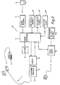
- FIG. 1 shows a remote activity monitoring system, which comprises telecommunications apparatus 1 of the type disclosed in GB A 2166321.
- the apparatus 1 is connected to a public switched telephone network (PSTN) 4 by way of which calls can be made to an emergency call receiving station 2, or to a subscriber's telephone 3.
- PSTN public switched telephone network
- the telecommunications apparatus 1 incorporates a microprocessor and application specific integrated circuit 9 by which it is controlled. It further includes a radio signal receiver 7, an automatic dialler 8, a non-volatile memory 10, such as an EEPROM, a loud speaker and microphone unit 11, a handset 12, a voice switching unit 13, a keypad 14, a call switch 15, a ring detector unit 16 having a first normal switching condition, a line switch 17, a tone ringer 18 and a tone signaller 19.
- the apparatus 1 also has associated with it one or more sensors 5. These might include, for example, a manually operated switch or switches mounted on the unit or remote therefrom, together with environmental detectors such as a smoke detector or a fire detector. Also associated with the apparatus is a control signal generator comprising a radio signal transmitter 6, in a form which may be conveniently be carried by a subscriber. A suitable generator might be worn on a cord around the neck of the subscriber, carried in the hand or a pocket, fastened to clothing or worn on the body using a "wristwatch" type strap.
- the memory 10 stores information concerned with the emergency call function of the unit and containing the emergency telephone number or numbers and unique identification code of the unit.
- the memory is also capable of storing telephone numbers for normal non-emergency use.
- an emergency call is initiated by operation of any one of the sensors 5, or by operation of the radio signal transmitter 6.
- a call progress light on the apparatus will flash, and a reassurance tone will sound from the speaker.
- the alarm may be reset using a cancel switch on the apparatus, in order to abort the call, and to return the apparatus to standby mode. If, after a predetermined period, no cancel signal has been generated, an alarm signal is applied to the microprocessor 9, which causes a call to be placed to a control centre, whose telephone number is retrieved from the memory 10. The call is placed by means of the automatic dialler 8 to a receiving station 2.
- the PSTN line is looped, and a hand-shaking routine is exchanged between the receiving station 2 and the apparatus of the invention.
- a hand-shake signal is received and decoded at the apparatus by the tone signaller 19.
- the microprocessor 9 transmits via the tone signaller 19, information coded appropriately for transmission over the PSTN, the information indicating at least the identity of the unit from which the call has originated, and the nature of the call (for example, as to whether the call is generated manually or in response to an alarm signal). Speech communication is then possible between the receiving station 2 and the subscriber, the subscriber using for example the loud speaker and microphone unit 11.
- the memory 10 may contain further emergency telephone numbers that can be used by the microprocessor 9 to initiate automatically dialled calls in the event that a first emergency call fails.
- the numbers stored in the memory 10 of the device will be that of the message reception centre 2, at which message reception apparatus is located.
- the memory 10 can store information regarding the alarm call function of the telephone device, including an identification code unique to the device.
- the apparatus includes means 20 for receiving data transmitted from the telephone device in response to input of an identification code or to an alarm signal, and a memory 22 for data corresponding to a plurality of identification codes which may be transmitted to it from the telephone device.
- the telephone device has associated with it an input device which comprises the keypad 14, which in normal operation of the telephone device can be used to input the number of another subscriber.
- the input device includes at least one remote RF transmitter 24 for transmitting an identification signal to the input device to identify a service provider.
- the input device has a dormant condition which it adopts during periods of inactivity and an active condition in which it can receive a signal transmitted from the transmitter 24.
- the device includes an activating trigger 26 in the form of an electric switch connected to the device by means of a pair of copper conductors 28 to switch the input device from its dormant condition to its active condition.
- Transmission of data to the message reception apparatus 2 can be initiated by entering an identification code using the keypad 14 of the input device.
- the code might identify, for example, a person providing a service, the company which is providing the service, or the nature of the service.
- the input device On input of a code, the input device causes the automatic dialling device 8 to connect the telephone apparatus 1 to the message reception apparatus 2 using a telephone number stored in the memory 10.
- an identification code can be entered into the input device when direct access to the device is not available, using the activating trigger 26 and the remote transmitter device 24.
- the trigger 26 is used to switch the input device from its dormant condition to its active condition, in which it can receive a signal from the transmitter 24.
- a signal would include a code, for example to identify a person or company providing a service, or the nature of a service.
- the input device On receipt of a signal from the transmitter 24, the input device causes the automatic dialling device 8 to connect the telephone apparatus 1 to the message receiving apparatus 2, in the manner described above.
- a service provider may activate the telephone apparatus (by pressing a special key on the keypad), enter an appropriate code number (such as a personal identification number followed by a service code number), then log the commencement or end of the service (by pressing another key on the keypad).
- an appropriate code number such as a personal identification number followed by a service code number
- a service provider may activate the telephone apparatus (by pressing a special button located outside the premises), then activate a suitably coded radio trigger.
- This method logs the time the service was provided, as well as details of the service provider. It also allows the service call to be logged quickly without requiring entry to the premises.
- the use of a suitable button also ensures that the radio trigger activates only the telephone apparatus within the premises, and not other telephone apparatus which is in range.
- the system of the invention can be used to measure that period.
- a person involved in the activity for example a provider of a service (such as a hairdresser visiting a resident in a sheltered housing complex), can input a code into the input device when the activity starts.
- a code can then be inputted into the device when the activity is completed.
- the device (or other component of the system) calculates the period between the times that the activity was started and completed, and information related to the period can be transmitted to the message receiving apparatus 2, for example to be recorded.
- the operation of an apparatus recording a period of time over which an activity takes place will be described in further detail below with reference to Figure 2.
- Operation of the device will generally be controlled by means of a microprocessor 9, for example using components of the call unit disclosed in GB A 2266321.
- a portable service provision monitoring device 25 embodying another aspect of the invention, in which parts common to the embodiment of Figure 1 are denoted by like reference numerals.
- the device 25 is suitable for use when it is desired to record data corresponding to the period of time during which a service is provided, for example, for accounting purposes.
- the device is also suitable for use when it is desired to record data corresponding to the time at which a service was provided, for example, a meal delivery.
- the device 25 is designed to be carried by the service provider so that details regarding the nature and duration of a service to be provided can be recorded at the location at which the service is provided.
- the device 25 is designed to be hand-held, and typically has dimensions of the order of 185x85x35mm, and a weight of generally less than 500g.
- the device 25 incorporates a microprocessor by which it is controlled, a radio receiver 7, a keypad 14, a non-volatile memory 10 such as an EEPROM, an LCD display module 27, a real time clock 29, a power supply 30, and a rechargeable power supply 31 such as a nickel cadmium battery.
- the device 25 also incorporates an integral modem 32 and interface means 33 for connecting the modem to the PSTN.
- the nickel cadmium battery 31 and power supply 30 are so arranged that the battery 31 can be recharged from the mains power supply at any appropriate location (such as the service provider's home or base).
- the power supply 30 includes a transformer (such as a plug-top transformer), which enables the device to be powered by mains electricity at any appropriate location.
- the device 25 is powered by the battery 31 when the device is used for entering and recording data relating to the nature and duration of the service provided and the identity of the recipient of the service.
- the modem 32 is provided for transmitting data stored in the device to a receiving station 2 (not shown in Figure 2) of the type shown in Figure 1 after a suitable number of service provider visits. It is designed so that it is powered in use from the mains by means of the power supply 30.
- the power supply 30 also includes circuiting for monitoring the terminal voltage of the battery 31 and causing the microprocessor 9 to display a warning signal on the LCD display module 27 when the remaining battery capacity is low.
- the radio receiver 7 of the embodiment of Figure 2 is activated by means of a remote RF transmitter 6, which, as described above, is supplied in a form which may conveniently be carried by a subscriber, such as worn on a cord around the neck of the subscriber, carried in the hand or a pocket, fastened to clothing or worn on the body using a "wristwatch" type strap.
- the service provider enters information relating to the nature of the service provided into the microprocessor 9 by means of the keypad 14. They then activate the device 25 from its dormant condition into its active condition (for example, by pressing a START button).
- the information entered into the microprocessor 9 will include an indication of the time of commencement of the service, by means of the real time clock 29.
- the time of commencement of the service is logged in response to the subscriber activating their radio transmitter 6 (or swiping their magnetic stripe card through a card reader).
- the radio transmitter 6 sends a unique identification signal to the radio receiver 7, which then enables data relating to the subscriber, such as the name and address of the subscriber to be entered into the microprocessor 9 along with the time and data entered by means of the keypad.
- the service provider enters information relating to the nature of the service provided into the microprocessor by means of the keypad 14. They then activate the device from its dormant condition to its active condition (for example, by pressing an END button). They then activate the radio transmitter 6 (or swipe the magnetic card) as before.
- An untimed service is defined as one in which it is desired to record the time at which the service was provided, but not the duration. If it is desired to record the time an untimed service was provided, the service provider enters information relating to the nature of the service provided using the keypad 14. They then activate the device from its dormant to its active condition (for example by pressing an END button). They then activate the radio transmitter 6 twice (or swipe the magnetic card twice).
- the service provider provides the same service to a series of subscribers, they will not need to enter the information relating to the nature of the service at each visit.
- the device will recall the previous service type setting in memory, so that at each visit the service provider needs only to check that the service set on the device is the same as the service being provided, before, for example pressing the START or END button.
- the memory 10 is designed such that it is capable of storing the data relating to of the order of 300 to 400 non-timed services, as well as other information relating to the functionality of the device 25.
- a warning message indicates this on the LCD display module 27, which alerts the service provider to the low remaining memory capacity and the need to download the data stored in the memory 10.
- the service provider can download the data by means of the modem 32 and telephone interface 33 via the PSTN to the message reception apparatus.
- the device 25 can also store data received from the message reception apparatus 2. By this method, it is possible to ensure that the real time clock 29 of the device maintains the same time as the message reception apparatus 2. It is also possible to amend any service provider codes or descriptions stored within the device 25.
Landscapes
- Engineering & Computer Science (AREA)
- Physics & Mathematics (AREA)
- General Physics & Mathematics (AREA)
- General Engineering & Computer Science (AREA)
- Theoretical Computer Science (AREA)
- Signal Processing (AREA)
- Computer Security & Cryptography (AREA)
- Business, Economics & Management (AREA)
- Emergency Management (AREA)
- Mobile Radio Communication Systems (AREA)
- Alarm Systems (AREA)
- Selective Calling Equipment (AREA)
Claims (14)
- Système de contrôle de prestataires de services, comprenant :dans lequela) un appareil téléphonique (1), qui inclut une mémoire (10) et des moyens (8) pour composer un numéro mémorisé dans la mémoire ;b) un dispositif d'entrée (14), au moyen duquel des codes d'identification peuvent être introduits dans l'appareil téléphonique ;c) un dispositif (2) de réception de messages, auquel une liaison (4) partant de l'appareil téléphonique peut être établie en utilisant un numéro mémorisé dans la mémoire de l'appareil téléphonique, le dispositif de réception de messages comprenant des moyens (20) pour recevoir des données transmises à partir de l'appareil téléphonique, et une mémoire (22),d) lesdits codes d'identification comprennenti) une identité d'un prestataire de services et/ou d'un service délivré ; etii) une identité d'emplacement ; etiii) un code d'événement ;e) ledit appareil téléphonique comporte des moyens aptes à répondre à l'entrée desdits codes d'identification pour établir ladite liaison et transmettre lesdits codes ; etf) ledit dispositif de réception de messages est adapté pour mémoriser, dans sa mémoire, les données correspondant auxdits codes.
- Système de contrôle de prestataires de services selon la revendication 1, caractérisé en ce que :en ce queg) le dispositif d'entrée possède un état inactif, qu'il prend pendant des périodes d'inactivité, et un état actif ; eth) le système comporte en outre un dispositif de déclenchement (24) pour commuter le dispositif d'entrée entre lesdits états inactif et actif.
- Système de contrôle de prestataires de services selon la revendication 2, caractérisé en ce queen ce quei) ledit dispositif de déclenchement est éloigné de l'appareil téléphonique ; etj) le système comprend un dispositif émetteur à distance (6) pour émettre un signal au dispositif d'entrée pour envoyer à l'appareil téléphonique l'identité dudit prestataire de services et/ou du service délivré et déclencher l'émission desdits codes d'identification en direction dudit dispositif de réception de message.
- Système de contrôle de prestataires de services selon la revendication 2 ou 3, caractérisé en ce que le dispositif de déclenchement est connecté au dispositif d'entrée au moyen de conducteurs électriques.
- Système de contrôle de prestataires de services selon la revendication 2, caractérisé en ce queen ce quek) ledit dispositif de déclenchement est distant de l'appareil téléphonique et déclenche l'émission d'un signal unique pour ledit emplacement ; etl) le système comprend un dispositif portable (25) comprenant :des moyens de mémoire (10) pour mémoriser au moins temporairement lesdits codes d'identification ; etdes moyens (7) pour valider les données devant être mémorisées dans lesdits moyens de mémoire, lesdits moyens de validation des données devant être mémorisées étant actionnés, en cours d'utilisation, en réponse à une activation dudit dispositif de déclenchement.
- Système de contrôle de prestataires de services selon la revendication 5, caractérisé en ce que ledit dispositif portable comprend des moyens de transmission de données (32, 33) pour valider une liaison devant être établie entre le dispositif et ledit dispositif de réception de messages de manière que lesdites données puissent être envoyées audit dispositif de réception de messages par l'intermédiaire de ladite liaison.
- Système de contrôle de prestataires de services selon l'une quelconque des revendications 3 ou 6, caractérisé en ce quem) le système contient un déclencheur d'alarme (5), au moyen duquel l'émission d'un signal d'alarme peut être déclenché, les moyens de réception de données situés dans le dispositif de réception de message comprenant des moyens pour recevoir des données émises dans l'appareil téléphonique en réponse à un signal d'alarme.
- Système de contrôle de prestataires de services selon l'une quelconque des revendications 3 à 7, caractérisé en ce que le système comprend des moyens pour calculer un intervalle de temps entre une première entrée de code et une seconde entrée de code.
- Système de contrôle de prestataires de services selon la revendication 8, caractérisé en ce que ledit code d'événement est l'intervalle de temps entre les arrivées desdites première et seconde entrées de codes.
- Procédé de contrôle à distance de la délivrance d'un service par un prestataire de services, le procédé étant caractérisé en ce qu'il comprend :a) l'utilisation d'un système tel que revendiqué dans la revendication 1, dans lequel l'appareil téléphonique et le dispositif d'entrée sont situés en un emplacement où ledit service doit être délivré et dont ledit dispositif de réception de message est distant ;b) les étapes d'entrée desdits codes d'identification lors de la délivrance dudit service par un prestataire de services, ce qui a pour effet que ledit appareil téléphonique établit une liaison avec ledit dispositif de réception de messages et transmet lesdits codes d'identification identifiant le dispositif de réception de messages :i) l'emplacement ; etii) le prestataire de services et/ou le service délivré ni ; etiii) un instant d'événement.
- Procédé selon la revendication 10, caractérisé en ce que le prestataire de service introduit lesdits codes d'identification au début et à la fin du service délivré.
- Procédé selon la revendication 11, caractérisé en ce que ledit appareil téléphonique envoie lesdits codes d'identification au dispositif de réception de message lors de l'introduction desdites première et seconde entrées et ledit instant d'événement, et dans tous les cas l'instant actuel, fourni par des moyens formant horloge dans l'appareil téléphonique, ledit dispositif de réception de messages calculant un intervalle de temps écoulé entre lesdites première et seconde entrées.
- Procédé selon la revendication 10, caractérisé en ce que le temps écoulé entre lesdites première et seconde entrées est mesuré par les moyens formant horloge situés dans l'appareil téléphonique, et ledit instant d'événement lors de l'émission desdits codes d'identification par l'appareil téléphonique est ledit temps écoulé.
- Procédé selon l'une quelconque des revendications 10 à 13, caractérisé en ce qu'il comporte en outre les étapes de commutation, par ledit prestataire de services, dudit appareil téléphonique d'un état inactif à un état actif par actionnement d'un dispositif de déclenchement disposé extérieurement, mais au voisinage dudit emplacement, et l'introduction desdits codes d'identification au moyen de la transmission d'un signal par un dispositif d'émission à l'appareil téléphonique porté par ledit prestataire de services.
Applications Claiming Priority (5)
| Application Number | Priority Date | Filing Date | Title |
|---|---|---|---|
| GB929219954A GB9219954D0 (en) | 1992-09-19 | 1992-09-19 | Remote activity monitoring |
| GB9219954 | 1992-09-19 | ||
| GB9310282A GB2270816B (en) | 1992-09-19 | 1993-05-19 | Remote activity monitoring |
| GB9310282 | 1993-05-19 | ||
| PCT/GB1993/001966 WO1994007323A1 (fr) | 1992-09-19 | 1993-09-17 | Procede et systeme de controle a distance d'activites |
Publications (2)
| Publication Number | Publication Date |
|---|---|
| EP0663131A1 EP0663131A1 (fr) | 1995-07-19 |
| EP0663131B1 true EP0663131B1 (fr) | 1998-06-24 |
Family
ID=26301660
Family Applications (1)
| Application Number | Title | Priority Date | Filing Date |
|---|---|---|---|
| EP93920963A Revoked EP0663131B1 (fr) | 1992-09-19 | 1993-09-17 | Procede et systeme de controle a distance d'activites |
Country Status (7)
| Country | Link |
|---|---|
| EP (1) | EP0663131B1 (fr) |
| AU (1) | AU4825893A (fr) |
| DE (1) | DE69319348T2 (fr) |
| DK (1) | DK0663131T3 (fr) |
| ES (1) | ES2118973T3 (fr) |
| GB (1) | GB2301263B (fr) |
| WO (1) | WO1994007323A1 (fr) |
Families Citing this family (5)
| Publication number | Priority date | Publication date | Assignee | Title |
|---|---|---|---|---|
| US5531700A (en) * | 1994-07-29 | 1996-07-02 | Cardiovascular Imaging Systems, Inc. | Convertible tip catheters and sheaths |
| US5540236A (en) * | 1994-08-05 | 1996-07-30 | Cardiovascular Imaging Systems, Incorporated | Guide wire exit port |
| DE20007223U1 (de) | 2000-04-20 | 2000-08-17 | Wollny, Siegfried, 24980 Schafflund | Überwachungsvorrichtung für das Bewohnen von Wohnobjekten |
| FR2835076B1 (fr) * | 2002-01-24 | 2004-06-25 | Solem Sa | Dispositif pour controler et evaluer sur une periode donnee l'execution cyclique d'activites executees par un prestataire aupres d'une pluralite de beneficiaires |
| FR2911423A1 (fr) * | 2007-01-17 | 2008-07-18 | Daniel Riahi | Alarme de detresse individuelle |
Family Cites Families (9)
| Publication number | Priority date | Publication date | Assignee | Title |
|---|---|---|---|---|
| GB2084773B (en) * | 1980-09-08 | 1984-02-22 | Etter Berwyn E | Assimilating utility meter data with electronic probing |
| AU549646B2 (en) * | 1980-09-10 | 1986-02-06 | Porta Printer Systems Inc. | Means of assimilating utility meter data |
| GB2106289B (en) * | 1981-09-15 | 1984-11-07 | Rowntree Mackintosh Plc | Data logging device |
| US4549264A (en) * | 1983-10-04 | 1985-10-22 | B.I. Incorporated | Time and accounting system |
| WO1987007106A1 (fr) * | 1986-05-12 | 1987-11-19 | Clinicom Incorporated | Terminal portatif pouvant etre tenu a la main comprenant un lecteur de code a barres optiques et des moyens emetteurs-recepteurs electromagnetiques pour une communication interactive sans fil avec une station de communications de base |
| GB2223116B (en) * | 1988-07-28 | 1992-08-19 | British Airways Plc | Transaction recording apparatus |
| GB2226670A (en) * | 1988-12-30 | 1990-07-04 | Alexander Speiser | Reports having identification data and printing thereof |
| JPH03127288A (ja) * | 1989-10-13 | 1991-05-30 | Hitachi Maxell Ltd | データ収集装置およびデータ収集システム |
| GB9102687D0 (en) * | 1991-02-08 | 1991-03-27 | Modern Vitalcall Ltd | Remote setting of alarm systems |
-
1993
- 1993-05-19 GB GB9616277A patent/GB2301263B/en not_active Expired - Fee Related
- 1993-09-17 ES ES93920963T patent/ES2118973T3/es not_active Expired - Lifetime
- 1993-09-17 DK DK93920963T patent/DK0663131T3/da active
- 1993-09-17 EP EP93920963A patent/EP0663131B1/fr not_active Revoked
- 1993-09-17 DE DE69319348T patent/DE69319348T2/de not_active Expired - Fee Related
- 1993-09-17 WO PCT/GB1993/001966 patent/WO1994007323A1/fr not_active Ceased
- 1993-09-17 AU AU48258/93A patent/AU4825893A/en not_active Abandoned
Also Published As
| Publication number | Publication date |
|---|---|
| WO1994007323A1 (fr) | 1994-03-31 |
| GB2301263A (en) | 1996-11-27 |
| GB9616277D0 (en) | 1996-09-11 |
| GB2301263B (en) | 1997-04-02 |
| AU4825893A (en) | 1994-04-12 |
| DK0663131T3 (da) | 1999-02-15 |
| DE69319348D1 (de) | 1998-07-30 |
| ES2118973T3 (es) | 1998-10-01 |
| DE69319348T2 (de) | 1998-10-29 |
| EP0663131A1 (fr) | 1995-07-19 |
Similar Documents
| Publication | Publication Date | Title |
|---|---|---|
| KR900007151B1 (ko) | 자동 대인 감시 시스템 | |
| CA1152600A (fr) | Systeme de controle et de signalisation | |
| US4304970A (en) | Telephone status monitor apparatus | |
| US5327482A (en) | Public cordless telephone system with coin/card insertion inhibiting means | |
| US8866589B2 (en) | Programmable communicator | |
| US5971921A (en) | Medical alarm system and methods | |
| US4259548A (en) | Apparatus for monitoring and signalling system | |
| US20030027547A1 (en) | Emergency communication system | |
| US20090227223A1 (en) | Versatile personal medical emergency communication system | |
| EP1575323B1 (fr) | Méthode pour appel d'urgence | |
| US4273961A (en) | Apparatus for communicating with processing apparatus over a telephone network | |
| WO2004013824A1 (fr) | Dispositif de signalisation d'alarme et systeme d'alarme | |
| GB2283389A (en) | Telephone subscriber presence detector | |
| GB2362545A (en) | Alarm systems | |
| EP0663131B1 (fr) | Procede et systeme de controle a distance d'activites | |
| US4273960A (en) | Apparatus for monitoring usage of a telephone | |
| JPH09172404A (ja) | 移動型電気機器の情報報知装置 | |
| AU729763B2 (en) | Remote activity monitoring system and method | |
| TW407423B (en) | Mobile phone system and method therefore and terminal used the system thereof | |
| GB2270816A (en) | Remote activity monitoring | |
| GB2266431A (en) | Telecommunications apparatus | |
| CA1160713A (fr) | Systeme a minuterie variable par telecommande | |
| JP2501437B2 (ja) | 住宅情報送信装置 | |
| JP3467423B2 (ja) | 介護監視システムの付属端末装置 | |
| WO2003098907A2 (fr) | Systeme d'alarme personnelle, procede et centre d'appels |
Legal Events
| Date | Code | Title | Description |
|---|---|---|---|
| PUAI | Public reference made under article 153(3) epc to a published international application that has entered the european phase |
Free format text: ORIGINAL CODE: 0009012 |
|
| 17P | Request for examination filed |
Effective date: 19950419 |
|
| AK | Designated contracting states |
Kind code of ref document: A1 Designated state(s): BE CH DE DK ES FR GB IT LI LU NL SE |
|
| 17Q | First examination report despatched |
Effective date: 19960605 |
|
| GRAG | Despatch of communication of intention to grant |
Free format text: ORIGINAL CODE: EPIDOS AGRA |
|
| GRAG | Despatch of communication of intention to grant |
Free format text: ORIGINAL CODE: EPIDOS AGRA |
|
| GRAH | Despatch of communication of intention to grant a patent |
Free format text: ORIGINAL CODE: EPIDOS IGRA |
|
| GRAH | Despatch of communication of intention to grant a patent |
Free format text: ORIGINAL CODE: EPIDOS IGRA |
|
| GRAA | (expected) grant |
Free format text: ORIGINAL CODE: 0009210 |
|
| AK | Designated contracting states |
Kind code of ref document: B1 Designated state(s): BE CH DE DK ES FR GB IT LI LU NL SE |
|
| PG25 | Lapsed in a contracting state [announced via postgrant information from national office to epo] |
Ref country code: LI Free format text: LAPSE BECAUSE OF FAILURE TO SUBMIT A TRANSLATION OF THE DESCRIPTION OR TO PAY THE FEE WITHIN THE PRESCRIBED TIME-LIMIT Effective date: 19980624 Ref country code: CH Free format text: LAPSE BECAUSE OF FAILURE TO SUBMIT A TRANSLATION OF THE DESCRIPTION OR TO PAY THE FEE WITHIN THE PRESCRIBED TIME-LIMIT Effective date: 19980624 |
|
| REG | Reference to a national code |
Ref country code: CH Ref legal event code: EP |
|
| REF | Corresponds to: |
Ref document number: 69319348 Country of ref document: DE Date of ref document: 19980730 |
|
| PG25 | Lapsed in a contracting state [announced via postgrant information from national office to epo] |
Ref country code: LU Free format text: LAPSE BECAUSE OF NON-PAYMENT OF DUE FEES Effective date: 19980917 |
|
| REG | Reference to a national code |
Ref country code: ES Ref legal event code: FG2A Ref document number: 2118973 Country of ref document: ES Kind code of ref document: T3 |
|
| ET | Fr: translation filed | ||
| REG | Reference to a national code |
Ref country code: CH Ref legal event code: PL |
|
| REG | Reference to a national code |
Ref country code: DK Ref legal event code: T3 |
|
| PLBI | Opposition filed |
Free format text: ORIGINAL CODE: 0009260 |
|
| PLBF | Reply of patent proprietor to notice(s) of opposition |
Free format text: ORIGINAL CODE: EPIDOS OBSO |
|
| PLAB | Opposition data, opponent's data or that of the opponent's representative modified |
Free format text: ORIGINAL CODE: 0009299OPPO |
|
| 26 | Opposition filed |
Opponent name: SIEMENS - ELEMA AB, SOLNA (SE) Effective date: 19990324 |
|
| R26 | Opposition filed (corrected) |
Opponent name: SIEMENS AG Effective date: 19990324 |
|
| NLR1 | Nl: opposition has been filed with the epo |
Opponent name: SIEMENS - ELEMA AB, SOLNA (SE) |
|
| PLBF | Reply of patent proprietor to notice(s) of opposition |
Free format text: ORIGINAL CODE: EPIDOS OBSO |
|
| PGFP | Annual fee paid to national office [announced via postgrant information from national office to epo] |
Ref country code: SE Payment date: 20000914 Year of fee payment: 8 |
|
| PGFP | Annual fee paid to national office [announced via postgrant information from national office to epo] |
Ref country code: BE Payment date: 20000927 Year of fee payment: 8 |
|
| PGFP | Annual fee paid to national office [announced via postgrant information from national office to epo] |
Ref country code: DK Payment date: 20000929 Year of fee payment: 8 |
|
| PG25 | Lapsed in a contracting state [announced via postgrant information from national office to epo] |
Ref country code: DK Free format text: LAPSE BECAUSE OF NON-PAYMENT OF DUE FEES Effective date: 20010917 |
|
| PGFP | Annual fee paid to national office [announced via postgrant information from national office to epo] |
Ref country code: GB Payment date: 20010917 Year of fee payment: 9 |
|
| PG25 | Lapsed in a contracting state [announced via postgrant information from national office to epo] |
Ref country code: SE Free format text: LAPSE BECAUSE OF NON-PAYMENT OF DUE FEES Effective date: 20010918 |
|
| PGFP | Annual fee paid to national office [announced via postgrant information from national office to epo] |
Ref country code: ES Payment date: 20010926 Year of fee payment: 9 Ref country code: FR Payment date: 20010926 Year of fee payment: 9 |
|
| PGFP | Annual fee paid to national office [announced via postgrant information from national office to epo] |
Ref country code: NL Payment date: 20010928 Year of fee payment: 9 |
|
| PG25 | Lapsed in a contracting state [announced via postgrant information from national office to epo] |
Ref country code: BE Free format text: LAPSE BECAUSE OF NON-PAYMENT OF DUE FEES Effective date: 20010930 |
|
| PGFP | Annual fee paid to national office [announced via postgrant information from national office to epo] |
Ref country code: DE Payment date: 20011122 Year of fee payment: 9 |
|
| REG | Reference to a national code |
Ref country code: GB Ref legal event code: IF02 |
|
| BERE | Be: lapsed |
Owner name: TUNSTALL GROUP P.L.C. Effective date: 20010930 |
|
| EUG | Se: european patent has lapsed |
Ref document number: 93920963.1 |
|
| REG | Reference to a national code |
Ref country code: DK Ref legal event code: EBP |
|
| PG25 | Lapsed in a contracting state [announced via postgrant information from national office to epo] |
Ref country code: GB Free format text: LAPSE BECAUSE OF NON-PAYMENT OF DUE FEES Effective date: 20020917 |
|
| PG25 | Lapsed in a contracting state [announced via postgrant information from national office to epo] |
Ref country code: ES Free format text: LAPSE BECAUSE OF NON-PAYMENT OF DUE FEES Effective date: 20020918 |
|
| PG25 | Lapsed in a contracting state [announced via postgrant information from national office to epo] |
Ref country code: NL Free format text: LAPSE BECAUSE OF NON-PAYMENT OF DUE FEES Effective date: 20030401 Ref country code: DE Free format text: LAPSE BECAUSE OF NON-PAYMENT OF DUE FEES Effective date: 20030401 |
|
| GBPC | Gb: european patent ceased through non-payment of renewal fee |
Effective date: 20020917 |
|
| PG25 | Lapsed in a contracting state [announced via postgrant information from national office to epo] |
Ref country code: FR Free format text: LAPSE BECAUSE OF NON-PAYMENT OF DUE FEES Effective date: 20030603 |
|
| REG | Reference to a national code |
Ref country code: FR Ref legal event code: ST |
|
| REG | Reference to a national code |
Ref country code: ES Ref legal event code: FD2A Effective date: 20031011 |
|
| PG25 | Lapsed in a contracting state [announced via postgrant information from national office to epo] |
Ref country code: IT Free format text: LAPSE BECAUSE OF NON-PAYMENT OF DUE FEES;WARNING: LAPSES OF ITALIAN PATENTS WITH EFFECTIVE DATE BEFORE 2007 MAY HAVE OCCURRED AT ANY TIME BEFORE 2007. THE CORRECT EFFECTIVE DATE MAY BE DIFFERENT FROM THE ONE RECORDED. Effective date: 20050917 |
|
| RDAF | Communication despatched that patent is revoked |
Free format text: ORIGINAL CODE: EPIDOSNREV1 |
|
| RDAG | Patent revoked |
Free format text: ORIGINAL CODE: 0009271 |
|
| STAA | Information on the status of an ep patent application or granted ep patent |
Free format text: STATUS: PATENT REVOKED |
|
| 27W | Patent revoked |
Effective date: 20060331 |