EP0663169B1 - Système de décharge de pression automatique pour support de matelas - Google Patents
Système de décharge de pression automatique pour support de matelas Download PDFInfo
- Publication number
- EP0663169B1 EP0663169B1 EP94402848A EP94402848A EP0663169B1 EP 0663169 B1 EP0663169 B1 EP 0663169B1 EP 94402848 A EP94402848 A EP 94402848A EP 94402848 A EP94402848 A EP 94402848A EP 0663169 B1 EP0663169 B1 EP 0663169B1
- Authority
- EP
- European Patent Office
- Prior art keywords
- patient
- air
- mattress
- pressure
- compartments
- Prior art date
- Legal status (The legal status is an assumption and is not a legal conclusion. Google has not performed a legal analysis and makes no representation as to the accuracy of the status listed.)
- Expired - Lifetime
Links
- 238000010276 construction Methods 0.000 claims description 48
- 230000037396 body weight Effects 0.000 claims description 33
- 238000000034 method Methods 0.000 claims description 19
- 238000012417 linear regression Methods 0.000 claims description 4
- 230000003247 decreasing effect Effects 0.000 claims description 3
- 238000012546 transfer Methods 0.000 claims description 3
- 239000003570 air Substances 0.000 description 168
- 239000000463 material Substances 0.000 description 4
- 206010011985 Decubitus ulcer Diseases 0.000 description 3
- 235000006508 Nelumbo nucifera Nutrition 0.000 description 3
- 240000002853 Nelumbo nucifera Species 0.000 description 3
- 235000006510 Nelumbo pentapetala Nutrition 0.000 description 3
- 208000004210 Pressure Ulcer Diseases 0.000 description 2
- 238000006243 chemical reaction Methods 0.000 description 2
- 230000008878 coupling Effects 0.000 description 2
- 238000010168 coupling process Methods 0.000 description 2
- 238000005859 coupling reaction Methods 0.000 description 2
- 230000001419 dependent effect Effects 0.000 description 2
- 239000004744 fabric Substances 0.000 description 2
- 239000006260 foam Substances 0.000 description 2
- 238000000611 regression analysis Methods 0.000 description 2
- 229920005830 Polyurethane Foam Polymers 0.000 description 1
- 239000012080 ambient air Substances 0.000 description 1
- 210000003484 anatomy Anatomy 0.000 description 1
- 238000009530 blood pressure measurement Methods 0.000 description 1
- 238000001816 cooling Methods 0.000 description 1
- 238000013461 design Methods 0.000 description 1
- 238000011161 development Methods 0.000 description 1
- 238000010586 diagram Methods 0.000 description 1
- 238000001035 drying Methods 0.000 description 1
- 230000000694 effects Effects 0.000 description 1
- 229920001971 elastomer Polymers 0.000 description 1
- 238000011156 evaluation Methods 0.000 description 1
- 239000012530 fluid Substances 0.000 description 1
- 238000010438 heat treatment Methods 0.000 description 1
- 238000012423 maintenance Methods 0.000 description 1
- 238000005259 measurement Methods 0.000 description 1
- 238000012544 monitoring process Methods 0.000 description 1
- 229920002635 polyurethane Polymers 0.000 description 1
- 239000004814 polyurethane Substances 0.000 description 1
- 239000011496 polyurethane foam Substances 0.000 description 1
- 230000002265 prevention Effects 0.000 description 1
- 239000012858 resilient material Substances 0.000 description 1
- 239000000126 substance Substances 0.000 description 1
- 238000010998 test method Methods 0.000 description 1
- 238000012360 testing method Methods 0.000 description 1
- 239000004753 textile Substances 0.000 description 1
- 230000000007 visual effect Effects 0.000 description 1
Images


Classifications
-
- A—HUMAN NECESSITIES
- A61—MEDICAL OR VETERINARY SCIENCE; HYGIENE
- A61G—TRANSPORT, PERSONAL CONVEYANCES, OR ACCOMMODATION SPECIALLY ADAPTED FOR PATIENTS OR DISABLED PERSONS; OPERATING TABLES OR CHAIRS; CHAIRS FOR DENTISTRY; FUNERAL DEVICES
- A61G7/00—Beds specially adapted for nursing; Devices for lifting patients or disabled persons
- A61G7/001—Beds specially adapted for nursing; Devices for lifting patients or disabled persons with means for turning-over the patient
-
- A—HUMAN NECESSITIES
- A61—MEDICAL OR VETERINARY SCIENCE; HYGIENE
- A61G—TRANSPORT, PERSONAL CONVEYANCES, OR ACCOMMODATION SPECIALLY ADAPTED FOR PATIENTS OR DISABLED PERSONS; OPERATING TABLES OR CHAIRS; CHAIRS FOR DENTISTRY; FUNERAL DEVICES
- A61G2203/00—General characteristics of devices
- A61G2203/30—General characteristics of devices characterised by sensor means
- A61G2203/34—General characteristics of devices characterised by sensor means for pressure
Definitions
- This invention relates to an automated pressure relief mattress support system and, more particularly, a mattress system employing flexible, pressurized air compartments, or cylinders, for patient support, with automated control of the air pressure in the cylinders to maintain an optimum air pressure which minimizes pressure between a patient and the mattress surface, and to move the patient from center supine to right and left side positions for selected periods of time.
- the present invention comprises an automated pressure relief air support mattress construction having a plurality of longitudinally extending, flexible air compartments, or cylindrical tubes, which are interconnected and normally uniformly pressurized to an optimum air pressure to minimize interface surface pressure between a patient and the mattress.
- the system is of simplified, economical construction and can be operated both passively and actively. In passive operation, the cylindrical air tubes of the mattress are inflated to within a defined pressure range which minimizes pressure at the patient/mattress interface and aids in prevention and treatment of pressure sores on the patient.
- the system also may be operated actively by connection to a pressurized air supply, control, and monitoring system for roll, or rotation, of a patient to right and left side positions, typically to selected angles of up to about 30 degrees, for selected dwell times. Rotation of the patient is accomplished by manual or automatic control of the air pressures in selected pairs of air tubes to achieve pre-determined pressure values.
- the mattress construction includes an outer cover of vapor-permeable material. Inside the cover are foam support layers of selected densities to contour to the body of the patient and reduce interface pressure. Flexible cylindrical air tubes extending in parallel longitudinal relation throughout the length of the mattress are maintained in supporting jackets to maintain proper position. The air tubes may be framed on each end and on both sides with polyurethane foam bolsters. Lateral slats may be positioned in the mattress to reduce "hammocking" of the patient and distribute weight forces of the patient's body.
- the control unit for the mattress system includes a source of pressurized air, such as an air compressor, or blower, a valve and manifold arrangement connecting the blower to the air tubes, air pressure sensors associated with the tubes, and control means including a microprocessor and a manual control panel for operating the valve and manifold arrangement in an active mode, automatically or manually, to provide air at a preselected pressure in the air tubes.
- a source of pressurized air such as an air compressor, or blower
- a valve and manifold arrangement connecting the blower to the air tubes
- air pressure sensors associated with the tubes air pressure sensors associated with the tubes
- control means including a microprocessor and a manual control panel for operating the valve and manifold arrangement in an active mode, automatically or manually, to provide air at a preselected pressure in the air tubes.
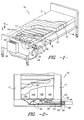
- the pressurized air mattress construction 10 of the present invention is of a generally rectangular shape having an outer cover 12 of suitable material, such as a vapor-permeable woven textile fabric, which encloses and contains a plurality of flexible, essentially air-impervious compartments, or cylindrical tubes 14a, 14b, extending longitudinally from head to foot of the mattress in side-by-side relation. Extending transversely across the mattress in parallel side-by-side relation may be a plurality of slats 16 of relatively resilient material which extend across the four air tubes 14a, 14b to permit are even body weight distribution across the mattress, thereby reducing pressure on the tissue and skin of the patient.
- suitable material such as a vapor-permeable woven textile fabric
- the mattress construction thus described may be placed on a conventional hospital bed frame 18, head and foot portions of which may be articulated to raise and lower upper and lower ends of the mattress. Due to the arrangement of the air tubes 14a, 14b in longitudinal, side-by-side position in the mattress construction, the mattress may be angularly positioned without changing the air pressure in the compartments as a result of articulation.
- the longitudinal air tubes comprise communicating left side and right side pairs, 14a and 14b, respectively.
- Tube pair 14a and tube pair 14b communicate by separate supply conduits 20, 22 to a pressurized air source.
- pressurized air supplied from a suitable air source, such as an air compressor, or pump P, is connected through a valve and manifold arrangement 28 to provide air at a desired pressure in each of the air tube pairs 14a and 14b, as will be explained.
- valves V1-V5 are solenoid-operated, either manually or in response to microprocessor program information to maintain a selected uniform optimum pressure in all air tubes to minimize patient/mattress interface pressures, or to move the patient between center supine and right and left side positions on the mattress, as will be described.
- the air tubes 14a, 14b of the mattress construction may be formed of a suitable flexible, essentially air-impervious material, such as a woven polymeric outer fabric sealed with a polymeric film, such as polyurethane.
- the tube construction ensures that air can be maintained at a desired pressure within the air tubes for an indefinite period of time, without the need for continuous supply of additional pressurized air to maintain such pressure, as in the case of the "low air loss" systems of the prior art.
- the four air tubes 14a, 14b of mattress construction 10 may be inflated to an air pressure to minimize patient/mattress interface pressure and reduce decubitus or pressure sores.
- Patient/mattress interface pressure may be conveniently measured by use of an interface pressure tester, such as an Ergo Check pressure measuring system manufactured by ABW, Gmbh of Germany.
- An optimum air pressure for the particular mattress construction described herein has been found, through interface pressure measurements, to reside within a narrow range for most, if not all, patient weights and sizes, and is established in the air tubes when the weight of a patient is on the mattress. In the mattress construction described, this optimum range has been found to be between about 1,7235kPa (0.250psi) and 2,4129kPa (0.350psi).
- the patient is placed in supine position on the bed at a given geographic elevational location and the air tubes pressurized or depressurized to the predetermined desired optimum value. Thereafter, the pressurized air source and its related equipment may be disconnected from the mattress and the mattress maintained at the optimum air pressure for the particular patient for an indefinite period of time.
- control valve and manifold arrangement 28 includes five direct-operated type, two-port solenoid valves V1-V5 with manifold M, such as a Series VVX21/22/23, manufactured by SMC Pneumatics, Inc. of Boston, Massachusetts.
- valves V1, V2 and V3 are normally closed valves and valves V4 and V5 are normally open valves, such that solenoid valves V1, V2, and V3 must be energized to open, while valves V4 and V5 must be energized to close.
- the manifold M has two sides, or compartments, one side or compartment M1 which communicates directly with valves V1, V2 and V3 and the inlet side of air pump P, and the other side or compartment M2 which communicates directly with valves V4 and V5 and the outlet side of air pump P. Under “no power" conditions, this arrangement of the valves and manifold ensures that the 14a and 14b air tube pairs of the mattress construction are cross-connected and pressure is equalized, as will be explained.
- the solenoid-operated valve and manifold arrangement 28 is electrically connected to and operated from microprocessor 46 (which may be an INTEL microprocessor #8051) and control panel 50.
- Valves V1-V5 and manifold compartments M1, M2 are interconnected by air flow lines 31, 32 to the inlet and outlet sides of air pump P and to the air tube pairs 14a and 14b by conduits 33-36.
- an air pressure sensor 40 such as a Sylvania Pressure Transducer No. MPX106P/9310 ( Figure 5), is operatively associated with each pair 14a and 14b of the air tubes to measure the internal air pressure in each pair.
- valve V1 communicates outside room air, as from air inlet 42, with manifold compartment M1
- valve V2 communicates air tube pair 14a and valve V4 with the manifold compartment M1
- valve V3 communicates the 14b pair of air tubes and valve V5 with the manifold compartment M1.
- valve V4 On the outlet or pressure side of pump P, in opened positions, valve V4 communicates manifold compartment M2 with the air tube pair 14a and valve V2, while valve V5 communicates the manifold compartment M2 with the 14b pair of air tubes and valve V3.
- the pressure sensor 40 located on the inside tube of each pair of tubes 14a, 14b is suitably operatively connected by electric leads 44 to the microprocessor unit 46 which contains programmed air pressure set point information to permit manual or automatic operation of the valves V1-V5 to introduce or remove air from the tube pairs to obtain a desired or preselected air pressure in the air tubes.
- FIG. 6 schematically illustrates the air tubes 14a, 14b and manifold and valve control arrangement 28, looking from the perspective of the foot of the bed, patient, and the air mattress.
- valve V1 is opened and pump P energized to supply air to the 14a and 14b pairs of air tubes via opened valves V4 and V5.
- valves V4 and V5 are closed to establish and maintain the desired set point uniform pressure in all four of the air tunes.
- the pump P is de-energized and valve V1 closed.
- valves V1, V2 and V3 are opened and valves V4 and V5 are closed.
- the pump remains de-energized while air is bled from the air tube pairs via valves V2 and V3, via the manifold compartment M1, and valve V1 to ambient air.
- valves V1, V2 and V3 are closed and valves V4 and V5 are closed.
- the mattress construction of the present invention may thereafter be disconnected from the pressurized air source and control means through quick-release coupling connectors 53, 54 (Fig. 3) and the mattress utilized with a uniform optimum air pressure in the air tubes based on the weight of the patient, at the particular geographic elevation of use.
- the air mattress construction of the present invention may also be used in an active mode to provide for orientation or adjustment of a patient from left to right side positions on the mattress by means of the control features and valving arrangement of the present invention.
- Air pressure set points for air tube pairs 14a and 14b may be established for various degrees of left or right side rotation of the patient from center supine position, typically from about 5 degrees up to about 30 degrees from the horizontal plane.
- valves V3 and V4 are opened, the pump started, and valve V5 is closed to transfer air from tube pair 14b to tube pair 14a.
- valve V3 is closed.
- valve V1 is opened and the pump operated to supply room or outside air to the 14a pair tubes.
- valve V1 is closed and V4 is closed. The pump is then stopped.
- valves V2 and V5 are opened, the pump is started, and valve V4 is closed to transfer air from the 14a pair tubes to the 14b pair tubes.
- valve V2 is closed.
- valve V1 is opened and the pump operated to supply air until the set point is reached on the 14b pair. At such time valve V1 is closed and valve V5 is closed. The pump is stopped.
- valve V1 is opened, the pump started, valves V4 and V5 are opened and valves 2 and 3 are closed to achieve preselected set points at 14a and 14b tubes. Valves V1, V4 and V5 are then closed and the pump stopped.
- valves V1, V2 and V3 are normally closed and valves V4 and V5 are normally open
- power failure automatically cross-connects the 14a and 14b tube pairs to equalize the pressure in the mattress construction.
- the normally opened and normally closed valves, V1-V5 are connected to the air tubes 14a, 14b to ensure their cross-connection and equalization of pressure in all of the air tubes.
- the communicating air conduit lines connecting the valves to the air tubes normally closed valves V1, V2, and V3 and normally opened valves V4 and V5 (under no-power conditions), communicate tubes 14a directly with tubes 14b by way of air lines 33, 35, valve V4, manifold compartment M2, valve V5, and air line 36.
- air tube pairs 14a and 14b of the mattress construction are connected in pairs by conduits 20, 22 respectively to the valve and manifold assembly 28, which is in turn operatively connected to the pump P by the solenoid-operated valves V1, V2, and V3 connected to the inlet side of the pump and solenoid valves V4 and V5 connected to the outlet side of the pump.
- Pressure sensors 40 located in inside tubes of the two pairs of tubes 14a and 14b are connected by suitable electrical leads to the microprocessor unit 46 containing programmable means for automated operation of the valve and manifold assembly and pump by way of electrical lines 48.
- the mattress construction and air control means may be used to move a bed patient from supine to right or left side angular positions which are accurately automatically established based on the body weight of a patient utilizing the bed. It has been found that a particular roll angle of a patient's body on the mattress construction of the present invention is directly affected by the patient's body weight. For example, to rotate a person of a given body weight to a given angular position, e.g., 30 degrees from the horizontal, requires a different internal air tube pressure from that of a person of a different bodyweight, due to the different air pressure required to maintain the patient in the desired angular position.
- the air pressure in the lower pressure side pair of tubes may be set at a preselected reduced pressure for the particular degree of patient roll, such that only the air pressure in the higher pressure side pair of air tubes need be varied, based on body weight, in accordance with program information. This reduces the amount of program information which must be employed to create the air pressure differential across the air mattress to produce the roll angle desired.
- the air pressure in the higher pressure side pair of air tubes may be set at a preselected amount and the lower pressure side air tube pair pressure varied, based on patient body weight. Additional data can be calculated, in the manner hereinafter disclosed, to simultaneously adjust both air tube pair air pressures, based on body weight, if desired.
- the automated control mattress construction of the present invention may be employed to measure body weight of a patient placed on the bed and to utilize such information through program control of the microprocessor to automatically adjust end-point internal air tube pressure settings necessary to locate a particular weight patient at a desired angular position, e.g., 5 degrees, 20 degrees, 30 degrees, relative to a horizontal plane.
- the following procedure was employed to establish the microprocessor program data for automatically setting the air pressure end points based on patient body weight.
- Patient subjects two male and two female, were used to obtain weight/air pressure information.
- Subject weights ranged from 54,43kg (120lbs) to 101,38kg (223.5lbs).
- An internal air pressure was set for an unoccupied inflated mattress construction having four 209,55 mm (8 1/4 inch) diameter air tunes.
- a subject patient then lay down upon the mattress and the internal air tube pressure for the loaded mattress was recorded.
- Four sets of measurements for each subject were recorded and differential pressure increases were claculated by subtracting the average increase or surge air pressure from the average unoccupied air mattress pressure.
- a patient of unknown weight was placed upon the mattress to obtain a pressure surge of 1,44774 kPa (.210 psi).
- a 101,38 kg (223.5 lbs) patient required a high side pair air tube inflation set point of 8,13492 kPa (1.18 psi) with a low side preset air pressure of 0,3447 kPa (0.05 psi) to achieve the 30 degree roll angle.
- This accumulated data may be employed in conventional known manner to program the microprocessor to establish automatic preset air pressure end points for exact patient body roll angles based on patient body weight.
- a patient having a body weight of 75,89 kg (167.3 lbs) may be rolled to a 30 degree angle of roll on right or left side by increasing the pressure set point in the two tubes on the side of the patient's body which is being raised, and by correspondingly decreasing air pressure in the two tubes on the low side of the patient.
- the two low side air tubes of the mattress are reduced in pressure from 1,7235 kPa (0.250 psi) (normal supine pressure) to 0,3447 kPa (0.05 psi).
- This low side air pressure has been found satisfactory for 30 degree angles of roll for patients of all body weights within the range tested. Thus it is only necessary to variably adjust the two air tubes lifting the patient's body.
- control means of the present invention may also be employed to sense a sudden pre-established large change in air pressure in the compartments of sufficiently large value indicative of the presence or absence of a bed patient on the mattress construction and to provide a signal, such as visual or aural indicator located at a suitable location, such as on control box 29 to alert an attendant of the absence or presence of a patient on the mattress construction.
Landscapes
- Health & Medical Sciences (AREA)
- Nursing (AREA)
- Life Sciences & Earth Sciences (AREA)
- Animal Behavior & Ethology (AREA)
- General Health & Medical Sciences (AREA)
- Public Health (AREA)
- Veterinary Medicine (AREA)
- Invalid Beds And Related Equipment (AREA)
- Mattresses And Other Support Structures For Chairs And Beds (AREA)
Claims (17)
- Procédé de support d'un patient dans un lit sur un matelas, comprenant les étapes suivantes :(a) la disposition d'un matelas (10) ayant plusieurs compartiments flexibles allongés (14a, 14b) pratiquement imperméables à l'air, s'étendent suivant la longueur du matelas côte à côte, les compartiments ayant des dispositifs droit et gauche de côté (14a, 14b) à tubes allongés qui supportent un patient sur lit à un emplacement géométrique déterminé d'utilisation sur le matelas,(b) la détermination de la pression pneumatique, dans les compartiments du matelas, qui réduit au minimum la pression à l'interface entre le patient et le matelas, et(c) la mise uniforme sous pression (20, 22, 28, P, 40, 44, 46, 50) des compartiments (14a, 14b) avec de l'air à la pression prédéterminée qui réduit au minimum la pression à l'interface entre le patient et le matelas.
- Procédé selon la revendication 1, comprenant la détection (40, 44, 46) de la pression pneumatique dans les compartiments lorsque le patient se trouve sur le matelas (10) à un emplacement géographique déterminé d'utilisation, et le maintien (20, 22, 28, P, 40, 44, 46, 50) de la pression dans les compartiments à la suite de la détection afin que la pression uniforme prédéterminée soit maintenue à l'intérieur.
- Procédé selon la revendication 1, comprenant l'étape de mise en communication (20, 22, 28, P, 40, 44, 46, 50) des dispositifs droit et gauche à tubes allongés (14a, 14b) pour le transfert d'air entre les dispositifs droit et gauche à tube de côté et pour l'introduction et l'extraction sélectives d'air.
- Procédé selon la revendication 1, comprenant l'étape de variation de la pression (20, 22, 28, P, 40, 44, 46, 50) dans un dispositif choisi parmi les dispositifs droit et gauche (14a, 14) à tubes de côté pour le déplacement d'un patient sélectivement vers des positions de côtés droit et gauche sur le matelas (10).
- Procédé selon la revendication 4, comprenant l'étape de maintien d'un patient en positions de côtés droit et gauche sur le matelas (10) pendant des péciodes prédéterminées (20, 22, 28, P, 40, 44, 46, 50) avec retour du patient en position horizontale couchée sur le dos sur le matelas.
- Procédé selon la revendication 5, comprenant l'étape de maintien automatique et de retour (20, 22, 28, P, 40, 44, 46, 50) du patient dans les positions de côtés droit et gauche et en position horizontale couchée sur le dos en fonction d'informations du programme.
- Procédé selon la revendication 1, comprenant une étape d'égalisation automatique des pressions (20, 22, 28) dans tous les compartiments en l'absence d'une source externe d'énergie pour mettre sous pression les compartiments afin que les dispositifs à tubes soient à des pressions égales.
- Procédé selon l'une quelconque des revendications 1 à 7, comprenant l'étape de disposition d'un matelas (10) ayant des paires adjacentes gauche et droite de côtés (14a, 14b) de compartiment qui communiquent directement (20, 22).
- Procédé selon la revendication 8, comprenant l'étape d'articulation des tronçons du matelas (10) sur lesquels est placé le patient avec maintien de la pression minimale à l'interface sans utilisation d'air comprimé supplémentaire.
- Procédé selon la revendication 8, comprenant des étapes supplémentaires de gonflage et de dégonflage sélectifs par pas (20, 22, 28, P, 40, 44, 46, 50) des paires de côtés droit et gauche des compartiments longitudinaux (14a, 14b) du matelas (10) pour le déplacement du patient sur le matelas de la position couchée sur le dos à la position sur le côté droit ou gauche.
- Procédé selon la revendication 8, comprenant l'étape supplémentaire d'augmentation de la pression pneumatique (20, 22, 28, P, 40, 44, 46, 50) dans tous les compartiments pneumatiques d'une quantité suffisante pour assurer un support rigide important du patient sur la construction du matelas (10) pour faciliter le traitement du patient, la disposition du patient sur le matelas et son extraction du matelas.
- Procédé selon la revendication 8, comprenant des étapes de détection (20, 22, 28, P, 40, 44, 46, 50) d'un changement prédéterminé de pression dans les compartiments, indicatif de la présence ou de l'absence d'un patient sur la construction de matelas (10), et la création d'un signal à la suite d'un tel changement.
- Procédé selon l'une quelconque des revendications 1 à 12, comprenant une étape de positionnement du corps d'un patient couché en position angulaire prédéterminée de côté à droite ou à gauche par rapport au plan horizontal d'une construction de matelas (10) ayant des dispositifs à tubes pneumatiques (14a, 14b) disposés longitudinalement du côté droit et du côté gauche et gonflables sélectivement à une pression pneumatique interne voulue pour le support et le déplacement du patient sur la construction de matelas, comprenant les étapes suivantes :(a) l'établissement (20, 22, 28, P, 40, 44, 46, 50) d'une pression pneumatique uniforme prédéterminée dans tous les dispositifs à tubes pneumatiques lorsque la construction de matelas n'est pas occupée par un patient,(b) la disposition de plusieurs patients de poids différents successivement sur la construction de matelas avec mesure des changements de pression pneumatique dans les dispositifs à tubes d'air sous l'action du poids de chaque patient placé sur le matelas,(c) la corrélation des divers changements de pression pneumatique dans les dispositifs à tubes pneumatiques dus au changement de pas du patient pour l'établissement d'une relation linéaire entre les variations de pression et les poids des corps des patients,(d) la disposition de plusieurs patients de poids différents successivement sur la construction de matelas et l'augmentation ou la réduction de la pression pneumatique dans les dispositifs à tubes pneumatiques des côtés gauche ou droit afin que le corps du patient soit déplacé sur le matelas pneumatique en position angulaire mesurée prédéterminée par rapport au plan horizontal et avec enregistrement de l'augmentation de la pression pneumatique nécessaire au déplacement du patient à l'angle prédéterminée,(e) la corrélation des augmentations enregistrées de pression nécessaires au déplacement des patients vers l'angle prédéterminé pour la détermination d'une relation linéaire entre les valeurs enregistrées, et(f) l'utilisation des informations obtenues à partir de la relation entre la pression pneumatique et le poids du corps du patient et de la relation obtenue entre la position angulaire et le poids du corps du patient pour la détermination automatique d'une limite de coupure de pression pneumatique dans les tubes pneumatiques du côté droit ou gauche lors d'un déplacement du corps du patient vers une position angulaire choisie d'après le poids du corps du patient.
- Procédé selon la revendication 13, comprenant une étape de corrélation des changements de pression pneumatique dans le dispositif à tubes pneumatiques et des changements de poids du patient par analyse par régression linéaire.
- Matelas (10) de support pneumatique d'un patient destiné à déplacer un patient d'une position horizontale couchée sur le dos à des positions sur le côté droit et le côté gauche, comprenant plusieurs compartiments flexibles et allongés (14a, 14b) pratiquement imperméables à l'air qui s'étendent suivant la longueur du matelas côte à côte, caractérisé par le fait que les compartiments comportent un dispositif à tubes allongés (14a, 14b) de côté droit et de côté gauche placés sous le patient, un dispositif à soupape (V1-V5) communiquant avec le dispositif à tubes pour l'introduction d'air dans le dispositif à tubes et l'extraction d'air de ce dispositif, et un dispositif de détection (40, 44, 46, 50) destiné à détecter et mesurer les variations de pression pneumatique dans les dispositifs à tubes des côtés droit et gauche entre l'absence et la présence du poids du corps du patient sur le dispositif à tubes, et à faire tourner le patient vers les positions angulaires prédéterminées du côté droit et du côté gauche par rapport au plan horizontal d'après les variations de la pression pneumatique.
- Matelas selon la revendication 15, caractérisé par le fait que le dispositif de détection comporte un dispositif (40) de détermination d'une augmentation de la pression pneumatique dans les dispositifs à tubes lorsque le poids du corps d'un patient est placé sur le lit, et un dispositif de programmation (20, 22, 28, P, 40, 44, 46, 50) destiné à utiliser les informations d'augmentation de pression d'air dans le dispositif à tubes pour faire varier la pression pneumatique entre les dispositifs à tubes du côté droit (14b) et du côté gauche (14a) de la construction du matelas (10) afin que le patient soit déplacé vers des positions angulaires prédéterminées du côté droit ou du côté gauche par rapport au plan horizontal.
- Matelas selon la revendication 15, caractérisé par le fait que le dispositif à soupape (V1-V5) comporte un dispositif (20, 22, 28, P, 40, 44, 48, 50) destiné à égaliser automatiquement les pressions dans tous les compartiments en l'absence d'une source extérieure d'alimentation pour la mise sous pression des compartiments.
Applications Claiming Priority (2)
| Application Number | Priority Date | Filing Date | Title |
|---|---|---|---|
| US179604 | 1988-04-11 | ||
| US08/179,604 US5487196A (en) | 1994-01-10 | 1994-01-10 | Automated pressure relief mattress support system |
Publications (2)
| Publication Number | Publication Date |
|---|---|
| EP0663169A1 EP0663169A1 (fr) | 1995-07-19 |
| EP0663169B1 true EP0663169B1 (fr) | 1999-03-10 |
Family
ID=22657257
Family Applications (1)
| Application Number | Title | Priority Date | Filing Date |
|---|---|---|---|
| EP94402848A Expired - Lifetime EP0663169B1 (fr) | 1994-01-10 | 1994-12-12 | Système de décharge de pression automatique pour support de matelas |
Country Status (4)
| Country | Link |
|---|---|
| US (1) | US5487196A (fr) |
| EP (1) | EP0663169B1 (fr) |
| CA (1) | CA2137726C (fr) |
| DE (1) | DE69416995T2 (fr) |
Cited By (1)
| Publication number | Priority date | Publication date | Assignee | Title |
|---|---|---|---|---|
| US8146191B2 (en) | 2004-04-30 | 2012-04-03 | Hill-Rom Services, Inc. | Patient support |
Families Citing this family (120)
| Publication number | Priority date | Publication date | Assignee | Title |
|---|---|---|---|---|
| US5606754A (en) * | 1989-03-09 | 1997-03-04 | Ssi Medical Services, Inc. | Vibratory patient support system |
| US5586346A (en) | 1994-02-15 | 1996-12-24 | Support Systems, International | Method and apparatus for supporting and for supplying therapy to a patient |
| US6892405B1 (en) * | 1994-05-09 | 2005-05-17 | Kci Licensing, Inc. | Therapeutic bed and related apparatus and methods |
| US6978501B2 (en) * | 1995-01-31 | 2005-12-27 | Kci Licensing, Inc. | Bariatric bed apparatus and methods |
| US6047424A (en) * | 1995-08-04 | 2000-04-11 | Hill-Rom, Inc. | Bed having modular therapy devices |
| US5630238A (en) * | 1995-08-04 | 1997-05-20 | Hill-Rom, Inc. | Bed with a plurality of air therapy devices, having control modules and an electrical communication network |
| US6119291A (en) * | 1995-08-04 | 2000-09-19 | Hill-Rom, Inc. | Percussion and vibration therapy apparatus |
| US6584628B1 (en) * | 1995-08-04 | 2003-07-01 | Hill-Rom Services, Inc. | Hospital bed having a rotational therapy device |
| US5794289A (en) * | 1995-10-06 | 1998-08-18 | Gaymar Industries, Inc. | Mattress for relieving pressure ulcers |
| US5745942A (en) * | 1995-10-19 | 1998-05-05 | Geomarine Systems, Inc. | Simplified control for lateral rotation therapy mattresses |
| US6115861A (en) * | 1997-10-09 | 2000-09-12 | Patmark Company, Inc. | Mattress structure |
| US5647079A (en) * | 1996-03-20 | 1997-07-15 | Hill-Rom, Inc. | Inflatable patient support surface system |
| US5815864A (en) * | 1996-04-02 | 1998-10-06 | Sytron Corporation | Microprocessor controller and method of initializing and controlling low air loss floatation mattress |
| US5966763A (en) * | 1996-08-02 | 1999-10-19 | Hill-Rom, Inc. | Surface pad system for a surgical table |
| US6536056B1 (en) * | 1996-11-18 | 2003-03-25 | John H. Vrzalik | Bariatric treatment system and related methods |
| US7346945B2 (en) * | 1996-11-18 | 2008-03-25 | Kci Licensing, Inc. | Bariatric treatment system and related methods |
| SE9700447D0 (sv) * | 1997-02-10 | 1997-02-10 | Herbert Lewin | Medicinsk madrass |
| US5963997A (en) * | 1997-03-24 | 1999-10-12 | Hagopian; Mark | Low air loss patient support system providing active feedback pressure sensing and correction capabilities for use as a bed mattress and a wheelchair seating system |
| US5926883A (en) * | 1997-08-13 | 1999-07-27 | Gaymar Industries, Inc. | Apparatus and method for controlling a patient positioned upon a cushion |
| CA2309751C (fr) | 1997-11-14 | 2008-01-22 | Span-America Medical Systems, Inc. | Surfaces de support pour patients |
| AU3972599A (en) * | 1998-05-06 | 1999-11-23 | Hill-Rom, Inc. | Mattress or cushion structure |
| US6447865B1 (en) | 1998-07-22 | 2002-09-10 | Gaymar Industries, Inc. | Gelatinous composite article and construction |
| US6099951A (en) * | 1998-07-22 | 2000-08-08 | Gaymar Industries, Inc. | Gelatinous composite article and construction |
| AU6395399A (en) | 1998-09-25 | 2000-04-17 | Isaac Fogel | Multiple module mattress system |
| US6885657B1 (en) * | 1998-11-30 | 2005-04-26 | Broadcom Corporation | Network telephony system |
| US20080028534A1 (en) * | 1999-04-20 | 2008-02-07 | M.P.L. Limited | Mattress having three separate adjustable pressure relief zones |
| US10357114B2 (en) * | 1999-04-20 | 2019-07-23 | Wcw, Inc. | Inflatable cushioning device with manifold system |
| US6269505B1 (en) | 1999-04-20 | 2001-08-07 | M.P.L. Ltd. | Inflatable cushioning device with manifold system |
| CH693299A5 (de) * | 1999-07-15 | 2003-05-30 | Doc Ag | Polster, insbesondere Matratze. |
| US6493888B1 (en) * | 2000-04-18 | 2002-12-17 | Hill-Rom Services, Inc. | Pediatric mattress |
| US6782574B2 (en) | 2000-07-18 | 2004-08-31 | Span-America Medical Systems, Inc. | Air-powered low interface pressure support surface |
| DK2140847T3 (da) | 2000-11-07 | 2012-08-27 | Tempur World Llc | Terapeutisk madrasanordning |
| US20020144343A1 (en) * | 2000-12-08 | 2002-10-10 | Kuiper Hendrik Klaas | Portable patient turning and lifting device |
| US6564411B2 (en) * | 2001-03-19 | 2003-05-20 | Shahzad Pirzada | Active fluid channeling system for a bed |
| US20050090721A1 (en) * | 2001-03-19 | 2005-04-28 | Shahzad Pirzada | Weighing and pump system for a bed |
| US6789283B2 (en) * | 2001-03-19 | 2004-09-14 | Shahzad Pirzada | Fluid filled support with a portable pressure adjusting device |
| US6401282B1 (en) * | 2001-05-14 | 2002-06-11 | Hai Shum | Modular mattress system |
| CA2416861A1 (fr) * | 2002-02-01 | 2003-08-01 | The Or Group,Inc. | Matelas pneumatique a enfoncement reduit |
| GB2387114A (en) * | 2002-04-02 | 2003-10-08 | Sareo Healthcare Ltd | Patient support structures |
| US6701551B1 (en) * | 2002-09-25 | 2004-03-09 | Steven J. Antinori | Upholstered slat box spring/bed |
| US7617554B2 (en) * | 2002-10-10 | 2009-11-17 | M.P.L. Ltd. | Pressure equalization apparatus |
| DE20216367U1 (de) | 2002-10-23 | 2003-03-06 | Foerner, Michael, 91220 Schnaittach | Liegevorrichtung |
| AU2003300995A1 (en) * | 2002-12-19 | 2004-07-22 | Hill-Rom Services, Inc. | Patient support surface |
| US20040261184A1 (en) * | 2003-06-27 | 2004-12-30 | Flick Roland E | Stand alone integrated cushion |
| US20050081300A1 (en) * | 2003-10-21 | 2005-04-21 | Span-America Medical Systems, Inc. | Two-mode therapeutic mattress system |
| US20050120479A1 (en) | 2003-12-03 | 2005-06-09 | Innovision Medica Technologies, Llc | Body positioning mattress |
| DE60304877T2 (de) * | 2003-12-19 | 2006-12-21 | Giovanni Beretta | Luftmatratze mit einer Druckregelungsvorrichtung |
| CN101090654B (zh) * | 2004-02-13 | 2012-03-14 | 约翰·W.·威尔金森 | 离散单元人体支撑以及用其提供动态按摩的方法 |
| US20060016016A1 (en) * | 2004-07-26 | 2006-01-26 | Hornbach David W | Modular bed system |
| US7253366B2 (en) * | 2004-08-09 | 2007-08-07 | Hill-Rom Services, Inc. | Exit alarm for a hospital bed triggered by individual load cell weight readings exceeding a predetermined threshold |
| US7676862B2 (en) * | 2004-09-13 | 2010-03-16 | Kreg Medical, Inc. | Siderail for hospital bed |
| US7743441B2 (en) | 2004-09-13 | 2010-06-29 | Kreg Therapeutics, Inc. | Expandable width bed |
| US7779494B2 (en) * | 2004-09-13 | 2010-08-24 | Kreg Therapeutics, Inc. | Bed having fixed length foot deck |
| US7757318B2 (en) * | 2004-09-13 | 2010-07-20 | Kreg Therapeutics, Inc. | Mattress for a hospital bed |
| US7287290B2 (en) * | 2004-09-23 | 2007-10-30 | Hill-Rom Services, Inc. | Mattress having an air pressure indicator |
| US9241580B2 (en) | 2005-01-14 | 2016-01-26 | Sage Products, Llc | Body transport apparatus with integrated handles |
| US9125777B2 (en) | 2005-01-14 | 2015-09-08 | Sage Products, Llc | Body transport apparatus |
| US7735164B1 (en) | 2005-01-14 | 2010-06-15 | Smart Medical Technology, Inc. | Disposable patient transfer mattress |
| US7114204B2 (en) * | 2005-01-14 | 2006-10-03 | Smart Medical Technology, Inc. | Method and apparatus for transferring patients |
| US8276222B1 (en) | 2005-01-14 | 2012-10-02 | Smart Medical Technology, Inc. | Patient transfer kit |
| FR2884708B1 (fr) * | 2005-04-22 | 2008-06-20 | Winncare Internat Soc Par Acti | Procede de determination automatique de la pression de gonflage a appliquer a un matelas dynamique |
| US8015972B2 (en) * | 2006-01-03 | 2011-09-13 | Shahzad Pirzada | System, device and process for remotely controlling a medical device |
| US7296314B2 (en) * | 2006-01-04 | 2007-11-20 | Encompass Group, Llc | Patient support surface |
| EP2019911B1 (fr) | 2006-05-09 | 2015-04-01 | Hill-Rom Services, Inc. | Matelas pulmonaire |
| US7657956B2 (en) * | 2006-08-04 | 2010-02-09 | Hill-Rom Services, Inc. | Patient support |
| US7849545B2 (en) | 2006-11-14 | 2010-12-14 | Hill-Rom Industries Sa | Control system for hospital bed mattress |
| US20080148677A1 (en) * | 2006-12-20 | 2008-06-26 | Huber Engineered Woods Llc | Reinforced Wood Panel |
| US20080235875A1 (en) * | 2007-03-28 | 2008-10-02 | Stryker Corporation | Maternity bed and patient lying surface therefor |
| US8108957B2 (en) | 2007-05-31 | 2012-02-07 | Hill-Rom Services, Inc. | Pulmonary mattress |
| GB2453371B (en) * | 2007-10-05 | 2010-06-23 | Philip James Hutchinson | Mattress pump apparatus controller, mattress pump apparatus, mattress and method of controlling a mattress |
| US20090144904A1 (en) * | 2007-12-10 | 2009-06-11 | David Moye | Inflatable hospital bed and method of using same |
| US9119753B2 (en) | 2008-06-27 | 2015-09-01 | Kreg Medical, Inc. | Bed with modified foot deck |
| US8801635B2 (en) * | 2008-10-03 | 2014-08-12 | Hlz Innovation, Llc | Adjustable pneumatic supporting surface |
| WO2010078047A2 (fr) * | 2008-12-17 | 2010-07-08 | Stryker Corporation | Support pour patient |
| FR2949320B1 (fr) | 2009-08-31 | 2012-11-16 | Hill Rom Ind Sa | Dispositif de basculement lateral |
| US8719984B2 (en) | 2009-10-02 | 2014-05-13 | Sizewise Rentals, L.L.C. | Segmented air foam mattress |
| WO2011153350A2 (fr) | 2010-06-02 | 2011-12-08 | Touchsensor Technologies, Llc | Dispositif thérapeutique de type support permettant la circulation sanguine dans les capillaires |
| US9659322B2 (en) | 2010-07-30 | 2017-05-23 | Xsensor Technology Corporation | Graphical display for recommending sleep comfort and support systems |
| DK3132781T3 (da) | 2010-10-05 | 2022-06-20 | Dabir Surfaces Inc | Bæreanordning, system og fremgangsmåde |
| USD690424S1 (en) | 2011-01-26 | 2013-09-24 | Sage Products, Inc. | Set of components for a patient repositioning system |
| US8458042B1 (en) | 2011-03-02 | 2013-06-04 | King Koil Licensing Company, Inc. | Methods for selecting a bedding mattress |
| US9211019B2 (en) | 2011-03-21 | 2015-12-15 | Rapid Air Llc. | Pump and housing configuration for inflating and deflating an air mattress |
| WO2012129326A1 (fr) | 2011-03-21 | 2012-09-27 | Rapid Air, Llc | Gonflage d'un matelas pneumatique à l'aide d'une pompe à couche-limite |
| WO2013010086A2 (fr) | 2011-07-13 | 2013-01-17 | Stryker Corporation | Support de prise en charge d'un patient ou d'une personne handicapée |
| US9833369B2 (en) | 2012-06-21 | 2017-12-05 | Hill-Rom Services, Inc. | Patient support systems and methods of use |
| US9228885B2 (en) | 2012-06-21 | 2016-01-05 | Hill-Rom Services, Inc. | Patient support systems and methods of use |
| WO2013192411A2 (fr) | 2012-06-21 | 2013-12-27 | Meyer Eric R | Systèmes de soutien pour patient et leurs procédés d'utilisation |
| US10292605B2 (en) | 2012-11-15 | 2019-05-21 | Hill-Rom Services, Inc. | Bed load cell based physiological sensing systems and methods |
| US8966689B2 (en) * | 2012-11-19 | 2015-03-03 | Select Comfort Corporation | Multi-zone fluid chamber and mattress system |
| US9433300B2 (en) | 2013-02-28 | 2016-09-06 | Hill-Rom Services, Inc. | Topper for a patient surface |
| US10238560B2 (en) | 2013-03-13 | 2019-03-26 | Hill-Rom Services, Inc. | Air fluidized therapy bed having pulmonary therapy |
| AU2014236803B2 (en) | 2013-03-14 | 2017-03-16 | Sleep Number Corporation | Inflatable air mattress autofill and off bed pressure adjustment |
| US10182661B2 (en) * | 2013-03-14 | 2019-01-22 | Sleep Number Corporation and Select Comfort Retail Corporation | Inflatable air mattress alert and monitoring system |
| EP3202284B1 (fr) | 2013-03-14 | 2018-10-03 | Select Comfort Corporation | Détection de ronflement et réponse pour un matelas pneumatique gonflable |
| US10179077B2 (en) | 2014-04-18 | 2019-01-15 | Kreg Medical, Inc. | Patient support with stand-up and sit features |
| WO2016028822A1 (fr) * | 2014-08-18 | 2016-02-25 | Huntleigh Technology Limited | Système à raccords |
| EP3242576B8 (fr) | 2015-01-05 | 2026-01-14 | Sleep Number Corporation | Lit avec suivi d'occupation par un utilisateur |
| US9308393B1 (en) | 2015-01-15 | 2016-04-12 | Dri-Em, Inc. | Bed drying device, UV lights for bedsores |
| US10441087B2 (en) | 2015-02-24 | 2019-10-15 | Sleep Number Corporation | Mattress with adjustable firmness |
| US11058227B2 (en) | 2015-04-23 | 2021-07-13 | Sealy Technology, Llc | Systems and methods for adjusting the firmness and profile of a mattress assembly |
| WO2017003764A1 (fr) | 2015-07-02 | 2017-01-05 | Select Comfort Corporation | Automatisation pour qualité de sommeil améliorée |
| US10238561B2 (en) | 2017-06-22 | 2019-03-26 | Piyush Sheth | System and method for treating and preventing pressure sores in bedridden patients |
| EP3731698B1 (fr) | 2017-12-28 | 2023-10-11 | Sleep Number Corporation | Lit ayant un élément de détection de ronflement |
| US11737938B2 (en) | 2017-12-28 | 2023-08-29 | Sleep Number Corporation | Snore sensing bed |
| US10932970B2 (en) * | 2018-08-27 | 2021-03-02 | Careview Communications, Inc. | Systems and methods for monitoring and controlling bed functions |
| WO2020174418A1 (fr) | 2019-02-26 | 2020-09-03 | Hill-Rom Services, Inc. | Appareil de positionnement de patient et matelas |
| US12527524B2 (en) | 2020-03-30 | 2026-01-20 | Hill-Rom Services, Inc. | Bed-based ballistocardiogram apparatus and method |
| US12310742B2 (en) | 2020-09-11 | 2025-05-27 | Xsensor Technology Corporation | Intelligent weight support system |
| US12357239B2 (en) | 2020-09-18 | 2025-07-15 | Xsensor Technology Corporation | Intelligent patient monitoring system |
| KR102559474B1 (ko) * | 2021-01-04 | 2023-07-24 | 허현승 | 욕창 방지용 에어 매트 |
| US12403057B1 (en) | 2021-04-16 | 2025-09-02 | Turn Medical, LLC | Proning face pack |
| US12226356B1 (en) | 2021-04-16 | 2025-02-18 | Turn Medical, LLC | Adjustable posterior head support |
| US12042440B1 (en) | 2021-04-16 | 2024-07-23 | Turn Medical, LLC | Stowable patient supports |
| US12121479B1 (en) | 2021-04-16 | 2024-10-22 | Turn Medical, LLC | Strap and release system |
| US12458551B1 (en) | 2021-04-16 | 2025-11-04 | Turn Medical, LLC | Stowable inner leg supports |
| CN113287901A (zh) * | 2021-06-24 | 2021-08-24 | 和也健康科技有限公司 | 一种床垫的稳压系统及其控制方法 |
| US12400410B2 (en) | 2021-10-28 | 2025-08-26 | Xsensor Technology Corporation | System and method for generating and visualizing virtual figures from pressure data captured using weight support devices for visualization of user movement |
| DE202023003005U1 (de) * | 2022-08-02 | 2025-07-30 | Sleep Number Corporation | Systeme zum Erkennen von vorhandenen Lackagen in Betten |
| US12557916B2 (en) | 2023-04-20 | 2026-02-24 | Sleep Number Corporation | Bed system for detecting snore side |
| US20250108945A1 (en) * | 2023-09-29 | 2025-04-03 | Wcw, Inc. | Body support and method of packing a body support |
Family Cites Families (20)
| Publication number | Priority date | Publication date | Assignee | Title |
|---|---|---|---|---|
| US4279044A (en) * | 1979-11-16 | 1981-07-21 | Owen Douglas | Fluid support system for a medical patient |
| US4897890A (en) * | 1983-01-05 | 1990-02-06 | Walker Robert A | Air control system for air bed |
| GB8417611D0 (en) * | 1984-07-10 | 1984-08-15 | Talley Medical Equipment Ltd | Control systems for air pads/mattresses |
| US4617690A (en) * | 1985-01-07 | 1986-10-21 | Whittaker Corporation | Inflatable bed patient mattress |
| US4694520A (en) * | 1986-01-15 | 1987-09-22 | Ssi Medical Services, Inc. | Patient support apparatus |
| US5003654A (en) * | 1986-09-09 | 1991-04-02 | Kinetic Concepts, Inc. | Method and apparatus for alternating pressure of a low air loss patient support system |
| US4949412A (en) * | 1986-11-05 | 1990-08-21 | Air Plus, Inc. | Closed loop feedback air supply for air support beds |
| US4797962A (en) * | 1986-11-05 | 1989-01-17 | Air Plus, Inc. | Closed loop feedback air supply for air support beds |
| US4803744A (en) * | 1987-05-19 | 1989-02-14 | Hill-Rom Company, Inc. | Inflatable bed |
| DE3804959C2 (de) * | 1988-02-18 | 2000-09-07 | Mannesmann Vdo Ag | Verfahren zum Befüllen von Luftkammern eines Sitzes |
| US4953247A (en) * | 1988-05-09 | 1990-09-04 | Hasty Charles E | Air-operated body support device |
| US4995124A (en) * | 1988-10-20 | 1991-02-26 | Sustena, Inc. | Constant pressure load bearing air chamber |
| US4949414A (en) * | 1989-03-09 | 1990-08-21 | Ssi Medical Services, Inc. | Modular low air loss patient support system and methods for automatic patient turning and pressure point relief |
| US5062167A (en) * | 1989-03-09 | 1991-11-05 | Ssi Medical Services, Inc. | Bimodal turning method |
| US5073999A (en) * | 1989-05-22 | 1991-12-24 | Ssi Medical Services, Inc. | Method for turning a patient with a low air loss patient support |
| US4989283A (en) * | 1989-06-12 | 1991-02-05 | Research Development Foundation | Inflation control for air supports |
| US5020176A (en) * | 1989-10-20 | 1991-06-04 | Angel Echevarria Co., Inc. | Control system for fluid-filled beds |
| US5070560A (en) * | 1990-10-22 | 1991-12-10 | Healthflex, Inc. | Pressure relief support system for a mattress |
| US5092007A (en) * | 1991-02-21 | 1992-03-03 | Hasty Charles E | Air mattress overlay for lateral patient roll |
| US5367728A (en) * | 1993-04-23 | 1994-11-29 | Chang; Ching-Lung | Adjustable ventilation mattress |
-
1994
- 1994-01-10 US US08/179,604 patent/US5487196A/en not_active Expired - Lifetime
- 1994-12-09 CA CA002137726A patent/CA2137726C/fr not_active Expired - Lifetime
- 1994-12-12 EP EP94402848A patent/EP0663169B1/fr not_active Expired - Lifetime
- 1994-12-12 DE DE69416995T patent/DE69416995T2/de not_active Expired - Lifetime
Cited By (1)
| Publication number | Priority date | Publication date | Assignee | Title |
|---|---|---|---|---|
| US8146191B2 (en) | 2004-04-30 | 2012-04-03 | Hill-Rom Services, Inc. | Patient support |
Also Published As
| Publication number | Publication date |
|---|---|
| CA2137726A1 (fr) | 1995-07-11 |
| CA2137726C (fr) | 1998-06-09 |
| EP0663169A1 (fr) | 1995-07-19 |
| DE69416995D1 (de) | 1999-04-15 |
| DE69416995T2 (de) | 1999-10-14 |
| US5487196A (en) | 1996-01-30 |
Similar Documents
| Publication | Publication Date | Title |
|---|---|---|
| EP0663169B1 (fr) | Système de décharge de pression automatique pour support de matelas | |
| EP0387045B1 (fr) | Système de support pour patients et méthode de fonctionement d'un système de support pour patients | |
| US5073999A (en) | Method for turning a patient with a low air loss patient support | |
| EP3032029B1 (fr) | Matelas pulmonaire | |
| US5182826A (en) | Method of blower control | |
| US5251349A (en) | Multi-modal patient support system | |
| CA1309212C (fr) | Structure de soutien pour les patients | |
| US5052067A (en) | Bimodal system for pressurizing a low air loss patient support | |
| US5095568A (en) | Modular low air loss patient support system | |
| US5121513A (en) | Air sack support manifold | |
| US5117518A (en) | Pressure controller | |
| US20110163885A1 (en) | Adjustable therapeutic mattress | |
| US8146191B2 (en) | Patient support | |
| EP0783287B1 (fr) | Procede et dispositif de support et de traitement d'un patient | |
| US5062167A (en) | Bimodal turning method | |
| WO1995021599A9 (fr) | Procede et dispositif de support et de traitement d'un patient | |
| WO2011006093A1 (fr) | Matelas thérapeutique ajustable | |
| US20220133563A1 (en) | Patient positioning apparatus and mattress | |
| US5065466A (en) | Quick disconnect coupling for a low air loss patient support | |
| US7287290B2 (en) | Mattress having an air pressure indicator | |
| EP3228294B1 (fr) | Dispositif de support pneumatique et système de commande | |
| CA2095644C (fr) | Systeme de support modulaire pour malade, a faible perte d'air, permettant de tourner automatiquement le malade et d'amortir les mouvemens aux points de pression | |
| HK1009928B (en) | Airsack support manifold apparatus |
Legal Events
| Date | Code | Title | Description |
|---|---|---|---|
| PUAI | Public reference made under article 153(3) epc to a published international application that has entered the european phase |
Free format text: ORIGINAL CODE: 0009012 |
|
| AK | Designated contracting states |
Kind code of ref document: A1 Designated state(s): BE DE FR GB IT NL SE |
|
| 17P | Request for examination filed |
Effective date: 19951122 |
|
| 17Q | First examination report despatched |
Effective date: 19960523 |
|
| GRAG | Despatch of communication of intention to grant |
Free format text: ORIGINAL CODE: EPIDOS AGRA |
|
| GRAG | Despatch of communication of intention to grant |
Free format text: ORIGINAL CODE: EPIDOS AGRA |
|
| GRAG | Despatch of communication of intention to grant |
Free format text: ORIGINAL CODE: EPIDOS AGRA |
|
| GRAH | Despatch of communication of intention to grant a patent |
Free format text: ORIGINAL CODE: EPIDOS IGRA |
|
| GRAH | Despatch of communication of intention to grant a patent |
Free format text: ORIGINAL CODE: EPIDOS IGRA |
|
| GRAA | (expected) grant |
Free format text: ORIGINAL CODE: 0009210 |
|
| AK | Designated contracting states |
Kind code of ref document: B1 Designated state(s): BE DE FR GB IT NL SE |
|
| REF | Corresponds to: |
Ref document number: 69416995 Country of ref document: DE Date of ref document: 19990415 |
|
| ET | Fr: translation filed | ||
| PLBE | No opposition filed within time limit |
Free format text: ORIGINAL CODE: 0009261 |
|
| STAA | Information on the status of an ep patent application or granted ep patent |
Free format text: STATUS: NO OPPOSITION FILED WITHIN TIME LIMIT |
|
| 26N | No opposition filed | ||
| REG | Reference to a national code |
Ref country code: GB Ref legal event code: IF02 |
|
| PGFP | Annual fee paid to national office [announced via postgrant information from national office to epo] |
Ref country code: SE Payment date: 20131206 Year of fee payment: 20 Ref country code: GB Payment date: 20131126 Year of fee payment: 20 |
|
| PGFP | Annual fee paid to national office [announced via postgrant information from national office to epo] |
Ref country code: IT Payment date: 20131216 Year of fee payment: 20 Ref country code: NL Payment date: 20131206 Year of fee payment: 20 Ref country code: FR Payment date: 20131126 Year of fee payment: 20 |
|
| PGFP | Annual fee paid to national office [announced via postgrant information from national office to epo] |
Ref country code: BE Payment date: 20131230 Year of fee payment: 20 |
|
| PGFP | Annual fee paid to national office [announced via postgrant information from national office to epo] |
Ref country code: DE Payment date: 20131230 Year of fee payment: 20 |
|
| REG | Reference to a national code |
Ref country code: DE Ref legal event code: R071 Ref document number: 69416995 Country of ref document: DE |
|
| REG | Reference to a national code |
Ref country code: NL Ref legal event code: V4 Effective date: 20141212 |
|
| REG | Reference to a national code |
Ref country code: GB Ref legal event code: PE20 Expiry date: 20141211 |
|
| PG25 | Lapsed in a contracting state [announced via postgrant information from national office to epo] |
Ref country code: GB Free format text: LAPSE BECAUSE OF EXPIRATION OF PROTECTION Effective date: 20141211 |
|
| REG | Reference to a national code |
Ref country code: SE Ref legal event code: EUG |