EP0663243A1 - Ventil für Sprühvorrichtung - Google Patents
Ventil für Sprühvorrichtung Download PDFInfo
- Publication number
- EP0663243A1 EP0663243A1 EP94119244A EP94119244A EP0663243A1 EP 0663243 A1 EP0663243 A1 EP 0663243A1 EP 94119244 A EP94119244 A EP 94119244A EP 94119244 A EP94119244 A EP 94119244A EP 0663243 A1 EP0663243 A1 EP 0663243A1
- Authority
- EP
- European Patent Office
- Prior art keywords
- rod
- valve
- liquid
- sprayer
- located below
- Prior art date
- Legal status (The legal status is an assumption and is not a legal conclusion. Google has not performed a legal analysis and makes no representation as to the accuracy of the status listed.)
- Granted
Links
- 239000007788 liquid Substances 0.000 claims abstract description 41
- 230000002093 peripheral effect Effects 0.000 claims abstract description 5
- 230000000694 effects Effects 0.000 abstract description 15
- 238000005507 spraying Methods 0.000 abstract description 12
- 238000000889 atomisation Methods 0.000 abstract description 4
- 230000035945 sensitivity Effects 0.000 abstract description 3
- 230000006835 compression Effects 0.000 description 11
- 238000007906 compression Methods 0.000 description 11
- 239000007921 spray Substances 0.000 description 5
- 239000002304 perfume Substances 0.000 description 4
- 239000012141 concentrate Substances 0.000 description 1
- 230000004048 modification Effects 0.000 description 1
- 238000012986 modification Methods 0.000 description 1
- 238000011084 recovery Methods 0.000 description 1
Images


Classifications
-
- B—PERFORMING OPERATIONS; TRANSPORTING
- B67—OPENING, CLOSING OR CLEANING BOTTLES, JARS OR SIMILAR CONTAINERS; LIQUID HANDLING
- B67D—DISPENSING, DELIVERING OR TRANSFERRING LIQUIDS, NOT OTHERWISE PROVIDED FOR
- B67D7/00—Apparatus or devices for transferring liquids from bulk storage containers or reservoirs into vehicles or into portable containers, e.g. for retail sale purposes
- B67D7/06—Details or accessories
- B67D7/58—Arrangements of pumps
- B67D7/60—Arrangements of pumps manually operable
-
- B—PERFORMING OPERATIONS; TRANSPORTING
- B65—CONVEYING; PACKING; STORING; HANDLING THIN OR FILAMENTARY MATERIAL
- B65D—CONTAINERS FOR STORAGE OR TRANSPORT OF ARTICLES OR MATERIALS, e.g. BAGS, BARRELS, BOTTLES, BOXES, CANS, CARTONS, CRATES, DRUMS, JARS, TANKS, HOPPERS, FORWARDING CONTAINERS; ACCESSORIES, CLOSURES, OR FITTINGS THEREFOR; PACKAGING ELEMENTS; PACKAGES
- B65D83/00—Containers or packages with special means for dispensing contents
- B65D83/14—Containers for dispensing liquid or semi-liquid contents by internal gaseous pressure, i.e. aerosol containers comprising propellant
- B65D83/44—Valves specially adapted for the discharge of contents; Regulating devices
- B65D83/48—Lift valves, e.g. operated by push action
-
- B—PERFORMING OPERATIONS; TRANSPORTING
- B05—SPRAYING OR ATOMISING IN GENERAL; APPLYING FLUENT MATERIALS TO SURFACES, IN GENERAL
- B05B—SPRAYING APPARATUS; ATOMISING APPARATUS; NOZZLES
- B05B11/00—Single-unit hand-held apparatus in which flow of contents is produced by the muscular force of the operator at the moment of use
- B05B11/01—Single-unit hand-held apparatus in which flow of contents is produced by the muscular force of the operator at the moment of use characterised by the means producing the flow
- B05B11/10—Pump arrangements for transferring the contents from the container to a pump chamber by a sucking effect and forcing the contents out through the dispensing nozzle
- B05B11/1001—Piston pumps
- B05B11/1016—Piston pumps the outlet valve having a valve seat located downstream a movable valve element controlled by a pressure actuated controlling element
- B05B11/1018—Piston pumps the outlet valve having a valve seat located downstream a movable valve element controlled by a pressure actuated controlling element and the controlling element cooperating with means for opening or closing the inlet valve
Definitions
- This invention relates to a valve for a sprayer, and more particularly to one which has teeth-like grooves and an inwardly recessed groove as shoulders thereof, of well as axial liquid introduction grooves as the outermost surface thereof to provide improved back pressure and upward introduction effects for liquid container connected with the sprayer.
- a forced sprayer (such as that for a perfume bottle) is known to be one which, in response to an external force, introduces a small amount of liquid from a container with which the sprayer is connected and sprays the liquid in an atomized form.
- a forced sprayer such as that for a perfume bottle
- Figs. 1-3 show several such press type sprayers, each of which comprises a press button A, a piston rod B, a housing C provided to enclose the opening of a bottle (not shown), a valve D, an internal sleeve E, a cylinder F, a spring G, a nozzle H, and a liquid introducing tube I.
- the housing C encloses an opening of a bottle (not shown) and the liquid introducing tube I is inserted in the bottle and immersed in the liquid contained in the bottle.
- the piston rod B moves downward along with the valve D within the cylinder F, and when the lower end of the valve D contacts the lower end of the cylinder F, a sealed compression chamber K is formed in the upper portion of the cylinder F, where a small amount of liquid flows in during the movement of the valve D. Further downward movement of the piston rod B reduces the volume of the chamber K and increases the pressure of the liquid in the chamber.
- valve D When a back pressure in the chamber is larger than the resilient force of the spring G, the valve D is forced to make an instant downward movement such the liquid in the chamber escapes through a gap formed between the valve D and the piston rod B and is sprayed in an atomized form through the nozzle H located near the press button A.
- a sprayer effect is satisfactory or not judged based on two considerations: (1) uniformness of atomization of the sprayed liquid, and (2) instant and sensitive response of spraying (i.e., a short time duration from the actuation of the press button to the actual spraying action from nozzle). These two factors are determined by the response of the valve D.
- a slow response of the valve D prolongs the response time from the actuation of the press button to the actual spraying action from the nozzle, and consequently can not provide a sufficient force to spray a necessary amount of liquid in a very short instant.
- a weak spraying force could lead to uniformness of atomization and degrade the spraying effect. If the liquid is perfume, a degraded spraying effect would severely deteriorate the quality of the perfume perceived by a consumer even if the perfume itself is of a high quality.
- the poor spraying effect of the conventional sprayers is resulted from a poor design of the back pressure area of the valve; the movement of the valve D in the chamber K can not result in a smooth upward flow of the liquid contained in the chamber, thereby lowering the sensitivity of the piston rod as well as reducing the amount and atomization effect of the sprayed liquid.
- the back pressure area D1 thereof is of a step-slant design; hence, liquid pressure can not concentrate on the area, and moreover liquid can not accumulate on the area to provide a sufficient pressure.
- the back pressure area D2 is designed to be in the form of a reservoir, which may provide a function to accumulate liquid, but it is difficult for liquid to flow smoothly from the lower part of the chamber K upward to the back pressure area D2; consequently, the effect thereof is still poor.
- the back pressure area D3 is provided with annular teeth, which may provide sufficient areas to receive liquid pressure, but it does still not provide a satisfactory accumulating effect for liquid on the area, and therefore the sprayer can still not provide a perfect spraying effect.
- an object of this invention is to provide an improved valve adapted for a small sprayer, in which a plurality of liquid introduction grooves are provided among thin and fine tubular elements such that liquid may flow effectively and may be sprayed in response to actuation by, e.g., the pressing of a press button.
- Another object of this invention is to provide a valve for a sprayer which is provided with teeth-like grooves and an inwardly recessed annular groove so as to accumulate sufficient amount of liquid and to increase the area which receives liquid pressure such that a sensitive valve which brings about instant spraying may be obtained.
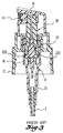
- the valve according to this invention includes: a first rod having a smaller diameter, a second rod located below the first rod and having a larger diameter in comparison with that of the first rod, a third rod located below the second rod and having a largest diameter, and a fourth rod located below the third rod and having a reduced diameter in comparison with that of the third rod; wherein a top end of the first rod is formed with a conic shape; an annular shoulder is formed between the first rod and the second rod, on which a plurality of teeth-like grooves are provided; another annular shoulder is formed between the second rod and the third rod, which is inwardly recessed to form an inwardly recessed annular groove; and an outer peripheral surface of the third rod is provided with a plurality of axial liquid introduction grooves.
- this invention is directed to the improvement of a valve 1 to thereby improved the sensitivity and spraying effect of the sprayer.
- the valve 1 comprises a first rod 11 having a smaller diameter, a second rod 12 located below the first rod and having a larger diameter, a third rod 13 located below the second rod and having a largest diameter, and a fourth rod 14 located below the third rod and having a reduced diameter in comparison with that of the third rod.
- the top (uppermost) end of the first rod 11 is formed with a conic shape so as to provide a needle-valve effect.
- An annular shoulder is former between the first rod 11 and the second rod 12, on which several teeth-like grooves 16 are provided in a concave-convex teeth-like arrangement; where the outer edges of the concave portions are encompassed by a thin side wall.
- Another annular shoulder formed between the second rod 12 and the third rod 13 is deeply inwardly recessed to form an inwardly recessed annular groove 17 which is located in a gap formed between a thin peripheral side wall of the third rod 13 and the second rod 12.
- the outer peripheral surface of the third rod is axially provided with a plurality of thin liquid introduction grooves 19.
- the bottom (lowermost) end of the fourth rod 14 is provided with a tapered edge 10 and an extending portion 18.
- the extending portion 18 may be surrounded by a spring 2.
- valve 1 when a piston rod 3 above the valve 1 is pressed to move the valve 1 downward, the tapered edge 10 is inserted into a small cylinder portion 43 below a larger cylinder portion 4 to thereby seal the internal space 40 of the larger cylinder such that the space 40 becomes a compression chamber.
- the valve 1 continues to move downward in the large cylinder portion 4 and creates downward pressure.
- the third rod 13 abuts against the internal wall of the cylinder portion 4 to divide the compression chamber 40 into a lower compression chamber 41 formed below the third rod and an upper compression chamber 42 formed above the third rod 13.
- the pressing force transmits downward through the piston rod 3, the valve 1 and spring 2.
- the liquid in the compression chamber 40 is compressed and is searched for an outlet where lower pressure exists.
- the teeth-like grooves 16 and the inwardly recessed annular groove 17 provide sufficient back pressure areas (there are no corresponding areas on the lower surface of the third rod 13 for liquid to exert a corresponding upward force to counteract the back pressure), and therefore the liquid may easily press down the valve 1 by means of the back pressure areas.
- the downward force is larger than the recovery force of the spring 2 and causes the conic portion 15 to depart from the piston rod 3.
- the liquid thrusts into the piston rod 3 and sprays out from a nozzle (not shown).
- a sufficient amount of liquid is required to press the valve 1 downward in the compression chamber 40 of the cylinder portion 4. Accordingly, the liquid in the lower compression chamber 41 has to effectively flow upward when the valve 1 is pressed downward, such that a smooth mutual movement between the liquid and the valve 1 may be achieved and the liquid may effectively spray through the piston rod 3 within the instant when the valve 1 moves downward due to the back pressure.
- the cylinder portion 4 thereof has a small bore, and therefore there is not much clearance installed.
- the outer wall surface of the third rod 13 is provided with a compression chamber 41 to the upper compression chamber 42.
- the teeth-like grooves 16 and the inwardly recessed annular groove 17 not only accumulate sufficient amount of liquid but also provide sufficient back pressure areas, whereby an excellent spraying effect is obtained.
Landscapes
- Engineering & Computer Science (AREA)
- Mechanical Engineering (AREA)
- Chemical & Material Sciences (AREA)
- Dispersion Chemistry (AREA)
- Catching Or Destruction (AREA)
- Containers And Packaging Bodies Having A Special Means To Remove Contents (AREA)
- Reciprocating Pumps (AREA)
- Special Spraying Apparatus (AREA)
- Fluid-Driven Valves (AREA)
- Details Of Valves (AREA)
- Nozzles (AREA)
Applications Claiming Priority (2)
| Application Number | Priority Date | Filing Date | Title |
|---|---|---|---|
| US165818 | 1993-12-14 | ||
| US08/165,818 US5370280A (en) | 1993-12-14 | 1993-12-14 | Valve for a sprayer |
Publications (2)
| Publication Number | Publication Date |
|---|---|
| EP0663243A1 true EP0663243A1 (de) | 1995-07-19 |
| EP0663243B1 EP0663243B1 (de) | 1999-05-06 |
Family
ID=22600613
Family Applications (1)
| Application Number | Title | Priority Date | Filing Date |
|---|---|---|---|
| EP94119244A Expired - Lifetime EP0663243B1 (de) | 1993-12-14 | 1994-12-06 | Ventil für Sprühvorrichtung |
Country Status (7)
| Country | Link |
|---|---|
| US (1) | US5370280A (de) |
| EP (1) | EP0663243B1 (de) |
| KR (1) | KR950018544U (de) |
| AT (1) | ATE179637T1 (de) |
| AU (1) | AU667019B2 (de) |
| CA (1) | CA2137893A1 (de) |
| DE (1) | DE69418299D1 (de) |
Cited By (1)
| Publication number | Priority date | Publication date | Assignee | Title |
|---|---|---|---|---|
| DE19638602A1 (de) * | 1995-10-31 | 1997-05-15 | Fritz Meckenstock | Auslaßventil, insbesondere für eine handbetätigte Pumpe und handbetätigte Pumpe |
Families Citing this family (6)
| Publication number | Priority date | Publication date | Assignee | Title |
|---|---|---|---|---|
| US5562234A (en) * | 1995-10-12 | 1996-10-08 | Su; Cheng-Yuan | Hand sprayer |
| US5579958A (en) * | 1995-10-12 | 1996-12-03 | Su; Cheng-Yuan | Liquid sprayer |
| US5687883A (en) * | 1995-11-16 | 1997-11-18 | Su; Cheng-Yuan | Inductor valve of an atomizer |
| US5692648A (en) * | 1995-11-16 | 1997-12-02 | Su; Cheng-Yuan | Sealing cap of an atomizer |
| KR100755809B1 (ko) * | 2001-03-23 | 2007-09-05 | 주식회사 종우실업 | 수동식 정량 분사 펌프 |
| TWI680065B (zh) * | 2019-03-27 | 2019-12-21 | 胡厚飛 | 毛筆之筆桿及使用於該筆桿之刀具 |
Citations (4)
| Publication number | Priority date | Publication date | Assignee | Title |
|---|---|---|---|---|
| SU806398A1 (ru) * | 1976-01-26 | 1981-02-23 | Chukalin Yurij A | Пневматический молоток |
| FR2626851A1 (fr) * | 1988-02-05 | 1989-08-11 | Step Soc Tech Pulverisation | Dispositif pour faciliter le remplissage des vaporisateurs |
| EP0342651A1 (de) * | 1988-05-18 | 1989-11-23 | Societe Technique De Pulverisation Step | Dosierpumpe |
| WO1993015845A1 (en) * | 1992-02-07 | 1993-08-19 | The Procter & Gamble Company | Spray pump package employing multiple orifices for dispensing liquid in different spray patterns with automatically adjusted optimized pump stroke for each pattern |
Family Cites Families (14)
| Publication number | Priority date | Publication date | Assignee | Title |
|---|---|---|---|---|
| US3908870A (en) * | 1973-11-15 | 1975-09-30 | Yoshino Kogyosho Co Ltd | Manual-type miniature atomizer |
| GB1473290A (en) * | 1975-03-28 | 1977-05-11 | Step Soc Tech Pulverisation | Liquid atomisers |
| FR2314772A2 (fr) * | 1975-06-19 | 1977-01-14 | Step Soc Tech Pulverisation | Perfectionnements apportes aux vaporisateurs |
| JPS5620052Y2 (de) * | 1975-07-21 | 1981-05-13 | ||
| IT1086022B (it) * | 1977-09-05 | 1985-05-28 | Coster Tecnologie Speciali Spa | Pompetta manuale alternativa nebulizzatrice di liquidi,come profumi ed altri liquidi |
| US4305530A (en) * | 1978-01-23 | 1981-12-15 | Yoshino Kogyosho Co., Ltd. | Liquid atomizer |
| US4271875A (en) * | 1978-09-21 | 1981-06-09 | Philip Meshberg | Dispenser adapted for fast pressure filling |
| AU534828B2 (en) * | 1979-05-16 | 1984-02-16 | Yoshino Kogosho Co. Ltd. | Atomizer |
| JPS583964U (ja) * | 1981-06-29 | 1983-01-11 | 株式会社吉野工業所 | 手動式小型噴霧器 |
| FR2512517A1 (fr) * | 1981-09-04 | 1983-03-11 | Aerosol Inventions Dev | Pompe-valve pour la distribution de liquides sous pression et procede de remplissage de recipients equipes d'une telle pompe-valve |
| US4606479A (en) * | 1984-04-16 | 1986-08-19 | Risdon Corporation | Pump for dispensing liquid from a container |
| FR2620052B1 (fr) * | 1987-09-09 | 1990-04-27 | Valois | Vaporisateur du type pompe manuelle a precompression pour utilisation avec un gaz propulseur |
| US4821928A (en) * | 1987-09-25 | 1989-04-18 | Su Cheng Y | Moveable valve structure for perfume atomizers |
| EP0345132B1 (de) * | 1988-06-02 | 1993-09-22 | Societe Technique De Pulverisation Step | Vordruck Dosierpumpe mit verbessertem Ansaugverhalten |
-
1993
- 1993-12-14 US US08/165,818 patent/US5370280A/en not_active Expired - Fee Related
-
1994
- 1994-12-06 EP EP94119244A patent/EP0663243B1/de not_active Expired - Lifetime
- 1994-12-06 AT AT94119244T patent/ATE179637T1/de not_active IP Right Cessation
- 1994-12-06 AU AU80250/94A patent/AU667019B2/en not_active Ceased
- 1994-12-06 DE DE69418299T patent/DE69418299D1/de not_active Expired - Lifetime
- 1994-12-12 CA CA002137893A patent/CA2137893A1/en not_active Abandoned
- 1994-12-13 KR KR2019940033783U patent/KR950018544U/ko not_active Ceased
Patent Citations (4)
| Publication number | Priority date | Publication date | Assignee | Title |
|---|---|---|---|---|
| SU806398A1 (ru) * | 1976-01-26 | 1981-02-23 | Chukalin Yurij A | Пневматический молоток |
| FR2626851A1 (fr) * | 1988-02-05 | 1989-08-11 | Step Soc Tech Pulverisation | Dispositif pour faciliter le remplissage des vaporisateurs |
| EP0342651A1 (de) * | 1988-05-18 | 1989-11-23 | Societe Technique De Pulverisation Step | Dosierpumpe |
| WO1993015845A1 (en) * | 1992-02-07 | 1993-08-19 | The Procter & Gamble Company | Spray pump package employing multiple orifices for dispensing liquid in different spray patterns with automatically adjusted optimized pump stroke for each pattern |
Non-Patent Citations (1)
| Title |
|---|
| DATABASE WPI Week 4781, Derwent World Patents Index; AN 81-m1282d * |
Cited By (1)
| Publication number | Priority date | Publication date | Assignee | Title |
|---|---|---|---|---|
| DE19638602A1 (de) * | 1995-10-31 | 1997-05-15 | Fritz Meckenstock | Auslaßventil, insbesondere für eine handbetätigte Pumpe und handbetätigte Pumpe |
Also Published As
| Publication number | Publication date |
|---|---|
| KR950018544U (ko) | 1995-07-22 |
| AU8025094A (en) | 1995-09-07 |
| ATE179637T1 (de) | 1999-05-15 |
| CA2137893A1 (en) | 1995-06-15 |
| EP0663243B1 (de) | 1999-05-06 |
| US5370280A (en) | 1994-12-06 |
| DE69418299D1 (de) | 1999-06-10 |
| AU667019B2 (en) | 1996-02-29 |
Similar Documents
| Publication | Publication Date | Title |
|---|---|---|
| CA2485237A1 (en) | Liquid jet pump | |
| US5788124A (en) | Device for packaging and dispensing a liquid or semi-liquid substance | |
| EP0930102B1 (de) | Handbetätigter zerstäuber für flüssigkeiten | |
| KR930005802Y1 (ko) | 향수 분무기용 가동 밸브 구조물 | |
| US5641097A (en) | Manual precompression pump for the spraying of a liquid and a dispensing unit fitted with such a pump | |
| EP0127449A1 (de) | Handbetätigter Flüssigkeitsspender | |
| US4022354A (en) | Accumulator release pump | |
| US5370280A (en) | Valve for a sprayer | |
| US5918778A (en) | Pump and pump securing device which maintains consistent dosage accuracy, and method of securing a pump to a container | |
| US4643338A (en) | Manual liquid dispenser | |
| EP1510259B1 (de) | Sprühpumpe | |
| JPS6319713B2 (de) | ||
| US3231153A (en) | Multiple spray rate pressurized package dispenser | |
| US7497356B2 (en) | Fluid dispenser device | |
| JP3193264B2 (ja) | ポンプ噴霧機 | |
| JPH06219478A (ja) | 予圧ポンプを有する液体噴霧用アッセンブリ | |
| JP2002035654A (ja) | スプレー容器 | |
| JPH0385169A (ja) | 香料、消臭剤等の自動噴射装置 | |
| EP4563240B1 (de) | Kleiner sprühpumpenkopf | |
| US5692648A (en) | Sealing cap of an atomizer | |
| JP7188860B2 (ja) | 噴霧スプレー | |
| CN219278331U (zh) | 一种自封口抑菌的化妆品容器喷头 | |
| US5687883A (en) | Inductor valve of an atomizer | |
| EP1334277A1 (de) | Handbetätigte pumpe zum ausstoss kleiner mengen | |
| US20070095940A1 (en) | Fluid product dispensing head |
Legal Events
| Date | Code | Title | Description |
|---|---|---|---|
| PUAI | Public reference made under article 153(3) epc to a published international application that has entered the european phase |
Free format text: ORIGINAL CODE: 0009012 |
|
| 17P | Request for examination filed |
Effective date: 19941206 |
|
| AK | Designated contracting states |
Kind code of ref document: A1 Designated state(s): AT BE CH DE DK ES FR GB GR IT LI LU NL SE |
|
| 17Q | First examination report despatched |
Effective date: 19960725 |
|
| GRAG | Despatch of communication of intention to grant |
Free format text: ORIGINAL CODE: EPIDOS AGRA |
|
| GRAG | Despatch of communication of intention to grant |
Free format text: ORIGINAL CODE: EPIDOS AGRA |
|
| GRAH | Despatch of communication of intention to grant a patent |
Free format text: ORIGINAL CODE: EPIDOS IGRA |
|
| GRAH | Despatch of communication of intention to grant a patent |
Free format text: ORIGINAL CODE: EPIDOS IGRA |
|
| GRAA | (expected) grant |
Free format text: ORIGINAL CODE: 0009210 |
|
| AK | Designated contracting states |
Kind code of ref document: B1 Designated state(s): AT BE CH DE DK ES FR GB GR IT LI LU NL SE |
|
| PG25 | Lapsed in a contracting state [announced via postgrant information from national office to epo] |
Ref country code: SE Free format text: THE PATENT HAS BEEN ANNULLED BY A DECISION OF A NATIONAL AUTHORITY Effective date: 19990506 Ref country code: NL Free format text: LAPSE BECAUSE OF FAILURE TO SUBMIT A TRANSLATION OF THE DESCRIPTION OR TO PAY THE FEE WITHIN THE PRESCRIBED TIME-LIMIT Effective date: 19990506 Ref country code: LI Free format text: LAPSE BECAUSE OF FAILURE TO SUBMIT A TRANSLATION OF THE DESCRIPTION OR TO PAY THE FEE WITHIN THE PRESCRIBED TIME-LIMIT Effective date: 19990506 Ref country code: IT Free format text: LAPSE BECAUSE OF FAILURE TO SUBMIT A TRANSLATION OF THE DESCRIPTION OR TO PAY THE FEE WITHIN THE PRE;WARNING: LAPSES OF ITALIAN PATENTS WITH EFFECTIVE DATE BEFORE 2007 MAY HAVE OCCURRED AT ANY TIME BEFORE 2007. THE CORRECT EFFECTIVE DATE MAY BE DIFFERENT FROM THE ONE RECORDED.SCRIBED TIME-LIMIT Effective date: 19990506 Ref country code: GR Free format text: LAPSE BECAUSE OF NON-PAYMENT OF DUE FEES Effective date: 19990506 Ref country code: FR Free format text: LAPSE BECAUSE OF FAILURE TO SUBMIT A TRANSLATION OF THE DESCRIPTION OR TO PAY THE FEE WITHIN THE PRESCRIBED TIME-LIMIT Effective date: 19990506 Ref country code: ES Free format text: THE PATENT HAS BEEN ANNULLED BY A DECISION OF A NATIONAL AUTHORITY Effective date: 19990506 Ref country code: CH Free format text: LAPSE BECAUSE OF FAILURE TO SUBMIT A TRANSLATION OF THE DESCRIPTION OR TO PAY THE FEE WITHIN THE PRESCRIBED TIME-LIMIT Effective date: 19990506 Ref country code: BE Free format text: LAPSE BECAUSE OF FAILURE TO SUBMIT A TRANSLATION OF THE DESCRIPTION OR TO PAY THE FEE WITHIN THE PRESCRIBED TIME-LIMIT Effective date: 19990506 Ref country code: AT Free format text: LAPSE BECAUSE OF FAILURE TO SUBMIT A TRANSLATION OF THE DESCRIPTION OR TO PAY THE FEE WITHIN THE PRESCRIBED TIME-LIMIT Effective date: 19990506 |
|
| REF | Corresponds to: |
Ref document number: 179637 Country of ref document: AT Date of ref document: 19990515 Kind code of ref document: T |
|
| REG | Reference to a national code |
Ref country code: CH Ref legal event code: EP |
|
| REF | Corresponds to: |
Ref document number: 69418299 Country of ref document: DE Date of ref document: 19990610 |
|
| PG25 | Lapsed in a contracting state [announced via postgrant information from national office to epo] |
Ref country code: DK Free format text: LAPSE BECAUSE OF FAILURE TO SUBMIT A TRANSLATION OF THE DESCRIPTION OR TO PAY THE FEE WITHIN THE PRESCRIBED TIME-LIMIT Effective date: 19990806 |
|
| PG25 | Lapsed in a contracting state [announced via postgrant information from national office to epo] |
Ref country code: DE Free format text: LAPSE BECAUSE OF FAILURE TO SUBMIT A TRANSLATION OF THE DESCRIPTION OR TO PAY THE FEE WITHIN THE PRESCRIBED TIME-LIMIT Effective date: 19990807 |
|
| EN | Fr: translation not filed | ||
| REG | Reference to a national code |
Ref country code: CH Ref legal event code: PL |
|
| PG25 | Lapsed in a contracting state [announced via postgrant information from national office to epo] |
Ref country code: LU Free format text: LAPSE BECAUSE OF NON-PAYMENT OF DUE FEES Effective date: 19991206 Ref country code: GB Free format text: LAPSE BECAUSE OF NON-PAYMENT OF DUE FEES Effective date: 19991206 |
|
| PLBE | No opposition filed within time limit |
Free format text: ORIGINAL CODE: 0009261 |
|
| STAA | Information on the status of an ep patent application or granted ep patent |
Free format text: STATUS: NO OPPOSITION FILED WITHIN TIME LIMIT |
|
| 26N | No opposition filed | ||
| GBPC | Gb: european patent ceased through non-payment of renewal fee |
Effective date: 19991206 |