EP0663279A2 - Verfahren zum Verschweissen von rohrförmigen Teilen - Google Patents
Verfahren zum Verschweissen von rohrförmigen Teilen Download PDFInfo
- Publication number
- EP0663279A2 EP0663279A2 EP95300157A EP95300157A EP0663279A2 EP 0663279 A2 EP0663279 A2 EP 0663279A2 EP 95300157 A EP95300157 A EP 95300157A EP 95300157 A EP95300157 A EP 95300157A EP 0663279 A2 EP0663279 A2 EP 0663279A2
- Authority
- EP
- European Patent Office
- Prior art keywords
- end faces
- tubular members
- contact
- tubular member
- heater
- Prior art date
- Legal status (The legal status is an assumption and is not a legal conclusion. Google has not performed a legal analysis and makes no representation as to the accuracy of the status listed.)
- Withdrawn
Links
- 238000003466 welding Methods 0.000 title claims abstract description 62
- 238000000034 method Methods 0.000 title claims abstract description 18
- 238000010438 heat treatment Methods 0.000 claims abstract description 41
- 229920005992 thermoplastic resin Polymers 0.000 claims abstract description 13
- 238000002844 melting Methods 0.000 claims description 5
- 230000008018 melting Effects 0.000 claims description 5
- 229920005989 resin Polymers 0.000 claims description 5
- 239000011347 resin Substances 0.000 claims description 5
- UCKMPCXJQFINFW-UHFFFAOYSA-N Sulphide Chemical compound [S-2] UCKMPCXJQFINFW-UHFFFAOYSA-N 0.000 claims description 3
- 229920000412 polyarylene Polymers 0.000 claims description 3
- 230000003213 activating effect Effects 0.000 claims description 2
- 239000011324 bead Substances 0.000 abstract description 9
- 230000004927 fusion Effects 0.000 abstract description 7
- 125000006850 spacer group Chemical group 0.000 description 22
- 239000004734 Polyphenylene sulfide Substances 0.000 description 5
- 230000007246 mechanism Effects 0.000 description 5
- 229920000069 polyphenylene sulfide Polymers 0.000 description 5
- 239000012530 fluid Substances 0.000 description 4
- 238000003825 pressing Methods 0.000 description 3
- 239000004696 Poly ether ether ketone Substances 0.000 description 2
- 239000000919 ceramic Substances 0.000 description 2
- 239000000463 material Substances 0.000 description 2
- 239000000155 melt Substances 0.000 description 2
- 238000012986 modification Methods 0.000 description 2
- 230000004048 modification Effects 0.000 description 2
- 229910001120 nichrome Inorganic materials 0.000 description 2
- 230000035515 penetration Effects 0.000 description 2
- 229920002530 polyetherether ketone Polymers 0.000 description 2
- 230000009467 reduction Effects 0.000 description 2
- 230000002441 reversible effect Effects 0.000 description 2
- 239000000126 substance Substances 0.000 description 2
- 229920003002 synthetic resin Polymers 0.000 description 2
- 239000000057 synthetic resin Substances 0.000 description 2
- 239000002033 PVDF binder Substances 0.000 description 1
- 239000004743 Polypropylene Substances 0.000 description 1
- 230000008901 benefit Effects 0.000 description 1
- 238000010276 construction Methods 0.000 description 1
- 238000001816 cooling Methods 0.000 description 1
- 238000010586 diagram Methods 0.000 description 1
- 238000009826 distribution Methods 0.000 description 1
- 238000002474 experimental method Methods 0.000 description 1
- 238000004898 kneading Methods 0.000 description 1
- 238000004519 manufacturing process Methods 0.000 description 1
- 238000007500 overflow downdraw method Methods 0.000 description 1
- 230000002093 peripheral effect Effects 0.000 description 1
- -1 polypropylene Polymers 0.000 description 1
- 229920001155 polypropylene Polymers 0.000 description 1
- 229920000915 polyvinyl chloride Polymers 0.000 description 1
- 239000004800 polyvinyl chloride Substances 0.000 description 1
- 229920002981 polyvinylidene fluoride Polymers 0.000 description 1
- 239000002904 solvent Substances 0.000 description 1
- 229920001169 thermoplastic Polymers 0.000 description 1
- 239000004416 thermosoftening plastic Substances 0.000 description 1
- 229910021642 ultra pure water Inorganic materials 0.000 description 1
- 239000012498 ultrapure water Substances 0.000 description 1
- XLYOFNOQVPJJNP-UHFFFAOYSA-N water Substances O XLYOFNOQVPJJNP-UHFFFAOYSA-N 0.000 description 1
Images



Classifications
-
- B—PERFORMING OPERATIONS; TRANSPORTING
- B29—WORKING OF PLASTICS; WORKING OF SUBSTANCES IN A PLASTIC STATE IN GENERAL
- B29C—SHAPING OR JOINING OF PLASTICS; SHAPING OF MATERIAL IN A PLASTIC STATE, NOT OTHERWISE PROVIDED FOR; AFTER-TREATMENT OF THE SHAPED PRODUCTS, e.g. REPAIRING
- B29C65/00—Joining or sealing of preformed parts, e.g. welding of plastics materials; Apparatus therefor
- B29C65/02—Joining or sealing of preformed parts, e.g. welding of plastics materials; Apparatus therefor by heating, with or without pressure
- B29C65/18—Joining or sealing of preformed parts, e.g. welding of plastics materials; Apparatus therefor by heating, with or without pressure using heated tools
- B29C65/20—Joining or sealing of preformed parts, e.g. welding of plastics materials; Apparatus therefor by heating, with or without pressure using heated tools with direct contact, e.g. using "mirror"
-
- B—PERFORMING OPERATIONS; TRANSPORTING
- B29—WORKING OF PLASTICS; WORKING OF SUBSTANCES IN A PLASTIC STATE IN GENERAL
- B29C—SHAPING OR JOINING OF PLASTICS; SHAPING OF MATERIAL IN A PLASTIC STATE, NOT OTHERWISE PROVIDED FOR; AFTER-TREATMENT OF THE SHAPED PRODUCTS, e.g. REPAIRING
- B29C65/00—Joining or sealing of preformed parts, e.g. welding of plastics materials; Apparatus therefor
- B29C65/02—Joining or sealing of preformed parts, e.g. welding of plastics materials; Apparatus therefor by heating, with or without pressure
- B29C65/14—Joining or sealing of preformed parts, e.g. welding of plastics materials; Apparatus therefor by heating, with or without pressure using wave energy, i.e. electromagnetic radiation, or particle radiation
- B29C65/1429—Joining or sealing of preformed parts, e.g. welding of plastics materials; Apparatus therefor by heating, with or without pressure using wave energy, i.e. electromagnetic radiation, or particle radiation characterised by the way of heating the interface
- B29C65/1432—Joining or sealing of preformed parts, e.g. welding of plastics materials; Apparatus therefor by heating, with or without pressure using wave energy, i.e. electromagnetic radiation, or particle radiation characterised by the way of heating the interface direct heating of the surfaces to be joined
-
- B—PERFORMING OPERATIONS; TRANSPORTING
- B29—WORKING OF PLASTICS; WORKING OF SUBSTANCES IN A PLASTIC STATE IN GENERAL
- B29C—SHAPING OR JOINING OF PLASTICS; SHAPING OF MATERIAL IN A PLASTIC STATE, NOT OTHERWISE PROVIDED FOR; AFTER-TREATMENT OF THE SHAPED PRODUCTS, e.g. REPAIRING
- B29C65/00—Joining or sealing of preformed parts, e.g. welding of plastics materials; Apparatus therefor
- B29C65/78—Means for handling the parts to be joined, e.g. for making containers or hollow articles, e.g. means for handling sheets, plates, web-like materials, tubular articles, hollow articles or elements to be joined therewith; Means for discharging the joined articles from the joining apparatus
- B29C65/7841—Holding or clamping means for handling purposes
-
- B—PERFORMING OPERATIONS; TRANSPORTING
- B29—WORKING OF PLASTICS; WORKING OF SUBSTANCES IN A PLASTIC STATE IN GENERAL
- B29C—SHAPING OR JOINING OF PLASTICS; SHAPING OF MATERIAL IN A PLASTIC STATE, NOT OTHERWISE PROVIDED FOR; AFTER-TREATMENT OF THE SHAPED PRODUCTS, e.g. REPAIRING
- B29C66/00—General aspects of processes or apparatus for joining preformed parts
- B29C66/01—General aspects dealing with the joint area or with the area to be joined
- B29C66/05—Particular design of joint configurations
- B29C66/10—Particular design of joint configurations particular design of the joint cross-sections
- B29C66/11—Joint cross-sections comprising a single joint-segment, i.e. one of the parts to be joined comprising a single joint-segment in the joint cross-section
- B29C66/114—Single butt joints
- B29C66/1142—Single butt to butt joints
-
- B—PERFORMING OPERATIONS; TRANSPORTING
- B29—WORKING OF PLASTICS; WORKING OF SUBSTANCES IN A PLASTIC STATE IN GENERAL
- B29C—SHAPING OR JOINING OF PLASTICS; SHAPING OF MATERIAL IN A PLASTIC STATE, NOT OTHERWISE PROVIDED FOR; AFTER-TREATMENT OF THE SHAPED PRODUCTS, e.g. REPAIRING
- B29C66/00—General aspects of processes or apparatus for joining preformed parts
- B29C66/50—General aspects of joining tubular articles; General aspects of joining long products, i.e. bars or profiled elements; General aspects of joining single elements to tubular articles, hollow articles or bars; General aspects of joining several hollow-preforms to form hollow or tubular articles
- B29C66/51—Joining tubular articles, profiled elements or bars; Joining single elements to tubular articles, hollow articles or bars; Joining several hollow-preforms to form hollow or tubular articles
- B29C66/52—Joining tubular articles, bars or profiled elements
- B29C66/522—Joining tubular articles
- B29C66/5221—Joining tubular articles for forming coaxial connections, i.e. the tubular articles to be joined forming a zero angle relative to each other
-
- B—PERFORMING OPERATIONS; TRANSPORTING
- B29—WORKING OF PLASTICS; WORKING OF SUBSTANCES IN A PLASTIC STATE IN GENERAL
- B29C—SHAPING OR JOINING OF PLASTICS; SHAPING OF MATERIAL IN A PLASTIC STATE, NOT OTHERWISE PROVIDED FOR; AFTER-TREATMENT OF THE SHAPED PRODUCTS, e.g. REPAIRING
- B29C66/00—General aspects of processes or apparatus for joining preformed parts
- B29C66/70—General aspects of processes or apparatus for joining preformed parts characterised by the composition, physical properties or the structure of the material of the parts to be joined; Joining with non-plastics material
- B29C66/73—General aspects of processes or apparatus for joining preformed parts characterised by the composition, physical properties or the structure of the material of the parts to be joined; Joining with non-plastics material characterised by the intensive physical properties of the material of the parts to be joined, by the optical properties of the material of the parts to be joined, by the extensive physical properties of the parts to be joined, by the state of the material of the parts to be joined or by the material of the parts to be joined being a thermoplastic or a thermoset
- B29C66/739—General aspects of processes or apparatus for joining preformed parts characterised by the composition, physical properties or the structure of the material of the parts to be joined; Joining with non-plastics material characterised by the intensive physical properties of the material of the parts to be joined, by the optical properties of the material of the parts to be joined, by the extensive physical properties of the parts to be joined, by the state of the material of the parts to be joined or by the material of the parts to be joined being a thermoplastic or a thermoset characterised by the material of the parts to be joined being a thermoplastic or a thermoset
- B29C66/7392—General aspects of processes or apparatus for joining preformed parts characterised by the composition, physical properties or the structure of the material of the parts to be joined; Joining with non-plastics material characterised by the intensive physical properties of the material of the parts to be joined, by the optical properties of the material of the parts to be joined, by the extensive physical properties of the parts to be joined, by the state of the material of the parts to be joined or by the material of the parts to be joined being a thermoplastic or a thermoset characterised by the material of the parts to be joined being a thermoplastic or a thermoset characterised by the material of at least one of the parts being a thermoplastic
- B29C66/73921—General aspects of processes or apparatus for joining preformed parts characterised by the composition, physical properties or the structure of the material of the parts to be joined; Joining with non-plastics material characterised by the intensive physical properties of the material of the parts to be joined, by the optical properties of the material of the parts to be joined, by the extensive physical properties of the parts to be joined, by the state of the material of the parts to be joined or by the material of the parts to be joined being a thermoplastic or a thermoset characterised by the material of the parts to be joined being a thermoplastic or a thermoset characterised by the material of at least one of the parts being a thermoplastic characterised by the materials of both parts being thermoplastics
-
- B—PERFORMING OPERATIONS; TRANSPORTING
- B29—WORKING OF PLASTICS; WORKING OF SUBSTANCES IN A PLASTIC STATE IN GENERAL
- B29C—SHAPING OR JOINING OF PLASTICS; SHAPING OF MATERIAL IN A PLASTIC STATE, NOT OTHERWISE PROVIDED FOR; AFTER-TREATMENT OF THE SHAPED PRODUCTS, e.g. REPAIRING
- B29C66/00—General aspects of processes or apparatus for joining preformed parts
- B29C66/90—Measuring or controlling the joining process
- B29C66/93—Measuring or controlling the joining process by measuring or controlling the speed
- B29C66/934—Measuring or controlling the joining process by measuring or controlling the speed by controlling or regulating the speed
- B29C66/93441—Measuring or controlling the joining process by measuring or controlling the speed by controlling or regulating the speed the speed being non-constant over time
-
- B—PERFORMING OPERATIONS; TRANSPORTING
- B29—WORKING OF PLASTICS; WORKING OF SUBSTANCES IN A PLASTIC STATE IN GENERAL
- B29C—SHAPING OR JOINING OF PLASTICS; SHAPING OF MATERIAL IN A PLASTIC STATE, NOT OTHERWISE PROVIDED FOR; AFTER-TREATMENT OF THE SHAPED PRODUCTS, e.g. REPAIRING
- B29C66/00—General aspects of processes or apparatus for joining preformed parts
- B29C66/90—Measuring or controlling the joining process
- B29C66/93—Measuring or controlling the joining process by measuring or controlling the speed
- B29C66/939—Measuring or controlling the joining process by measuring or controlling the speed characterised by specific speed values or ranges
-
- B—PERFORMING OPERATIONS; TRANSPORTING
- B29—WORKING OF PLASTICS; WORKING OF SUBSTANCES IN A PLASTIC STATE IN GENERAL
- B29C—SHAPING OR JOINING OF PLASTICS; SHAPING OF MATERIAL IN A PLASTIC STATE, NOT OTHERWISE PROVIDED FOR; AFTER-TREATMENT OF THE SHAPED PRODUCTS, e.g. REPAIRING
- B29C66/00—General aspects of processes or apparatus for joining preformed parts
- B29C66/90—Measuring or controlling the joining process
- B29C66/96—Measuring or controlling the joining process characterised by the method for implementing the controlling of the joining process
- B29C66/967—Measuring or controlling the joining process characterised by the method for implementing the controlling of the joining process involving special data inputs or special data outputs, e.g. for monitoring purposes
- B29C66/9672—Measuring or controlling the joining process characterised by the method for implementing the controlling of the joining process involving special data inputs or special data outputs, e.g. for monitoring purposes involving special data inputs, e.g. involving barcodes, RFID tags
-
- B—PERFORMING OPERATIONS; TRANSPORTING
- B29—WORKING OF PLASTICS; WORKING OF SUBSTANCES IN A PLASTIC STATE IN GENERAL
- B29C—SHAPING OR JOINING OF PLASTICS; SHAPING OF MATERIAL IN A PLASTIC STATE, NOT OTHERWISE PROVIDED FOR; AFTER-TREATMENT OF THE SHAPED PRODUCTS, e.g. REPAIRING
- B29C65/00—Joining or sealing of preformed parts, e.g. welding of plastics materials; Apparatus therefor
- B29C65/78—Means for handling the parts to be joined, e.g. for making containers or hollow articles, e.g. means for handling sheets, plates, web-like materials, tubular articles, hollow articles or elements to be joined therewith; Means for discharging the joined articles from the joining apparatus
- B29C65/7802—Positioning the parts to be joined, e.g. aligning, indexing or centring
- B29C65/782—Positioning the parts to be joined, e.g. aligning, indexing or centring by setting the gap between the parts to be joined
-
- B—PERFORMING OPERATIONS; TRANSPORTING
- B29—WORKING OF PLASTICS; WORKING OF SUBSTANCES IN A PLASTIC STATE IN GENERAL
- B29C—SHAPING OR JOINING OF PLASTICS; SHAPING OF MATERIAL IN A PLASTIC STATE, NOT OTHERWISE PROVIDED FOR; AFTER-TREATMENT OF THE SHAPED PRODUCTS, e.g. REPAIRING
- B29C66/00—General aspects of processes or apparatus for joining preformed parts
- B29C66/70—General aspects of processes or apparatus for joining preformed parts characterised by the composition, physical properties or the structure of the material of the parts to be joined; Joining with non-plastics material
- B29C66/71—General aspects of processes or apparatus for joining preformed parts characterised by the composition, physical properties or the structure of the material of the parts to be joined; Joining with non-plastics material characterised by the composition of the plastics material of the parts to be joined
-
- B—PERFORMING OPERATIONS; TRANSPORTING
- B29—WORKING OF PLASTICS; WORKING OF SUBSTANCES IN A PLASTIC STATE IN GENERAL
- B29C—SHAPING OR JOINING OF PLASTICS; SHAPING OF MATERIAL IN A PLASTIC STATE, NOT OTHERWISE PROVIDED FOR; AFTER-TREATMENT OF THE SHAPED PRODUCTS, e.g. REPAIRING
- B29C66/00—General aspects of processes or apparatus for joining preformed parts
- B29C66/90—Measuring or controlling the joining process
- B29C66/94—Measuring or controlling the joining process by measuring or controlling the time
-
- B—PERFORMING OPERATIONS; TRANSPORTING
- B29—WORKING OF PLASTICS; WORKING OF SUBSTANCES IN A PLASTIC STATE IN GENERAL
- B29C—SHAPING OR JOINING OF PLASTICS; SHAPING OF MATERIAL IN A PLASTIC STATE, NOT OTHERWISE PROVIDED FOR; AFTER-TREATMENT OF THE SHAPED PRODUCTS, e.g. REPAIRING
- B29C66/00—General aspects of processes or apparatus for joining preformed parts
- B29C66/90—Measuring or controlling the joining process
- B29C66/94—Measuring or controlling the joining process by measuring or controlling the time
- B29C66/949—Measuring or controlling the joining process by measuring or controlling the time characterised by specific time values or ranges
Definitions
- the present invention relates to a butt welding method or butt fusion method, more particularly, an apparatus and a method for connecting a pair of tubular members made of a thermoplastic resin by heating end faces thereof and then pressing them together.
- Tubular members made of a variety of synthetic resins are conventionally used in various applications.
- tubular members formed of a general-purpose thermoplastic resin such as polyvinyl chloride, polypropylene, etc. are popularly used as distributing water pipes in houses or plants, etc., pipes for chemicals, etc.
- tubular members made of a thermoplastic resin excellent in heat resistance and solvent resistance such as a polyphenylene sulfide resin (hereinafter referred to as "PPS"), polyether ether ketone, polyvinylidene fluoride, etc. are used as pipes for ultrapure water in fabrication of electronic devices such as LSI etc.
- PPS polyphenylene sulfide resin
- polyether ether ketone polyether ether ketone
- polyvinylidene fluoride etc.
- tubular members of thermoplastic synthetic resins it may be necessary to connect a tubular member to another or to connect a tubular member to a tubular end of an instrument.
- One known connection method between tubular members is a welding method in which a heater heats and melts end faces of two tubular members opposed to each other and thereafter the melted end faces are urged against each other to be connected thereby.
- a well-known apparatus used for the contact type welding method is for example one as disclosed in Japanese Patent Laid-open No. 63-4938, while a well-known apparatus used for the non-contact type welding method is for example one as disclosed in Japanese Patent Laid-open No. 5-193004.
- Either one of the conventional apparatus comprises clamps for holding a pair of tubular members to be welded horizontally and coaxially, and a heater set between the clamps, wherein one clamp can be moved toward or away from the other clamp by means of a pneumatic cylinder or a hydraulic cylinder and wherein the heater is arranged to be capable of receding from a moving path of the tubular member.
- Such apparatus can join the tubular members to each other by moving the movable clamp toward the other clamp after the heater melts the end faces of the tubular members to be welded.
- the above welding apparatus are arranged to weld the tubular members in such a manner that the end faces of the tubular members heated and melted are pressed against each other under a constant pressure by a pneumatic cylinder or fluid cylinder. Accordingly, the melted end faces are pressed against each other until the pressure of the fluid cylinder is balanced by reactive force of the melted end faces of the tubular members.
- the degree of fusion or melting is different between resins of the same chemical structure made by the same maker even with heating at the same temperature, because there are variations in molecular weight distribution, kneading, etc.
- the degree of fusion of the end faces of the tubular members is greatly influenced by the ambient temperature, presence or absence of convection, etc.
- welding results are not always constant even if the press-contact pressure is kept constant. For example, if the fusion depth of the end faces of the tubular members is too shallow, the projection or bead formed on the inner circumferential surface or the outer circumferential surface of a weld portion becomes small; conversely, if the fusion depth is too deep, the bead becomes large.
- Japanese Patent Laid-open No. 63-4938 discloses another means in such an arrangement that the end faces of the tubular members are brought into contact with each other, then one of the tubular members is moved by a hydraulic cylinder up to a position where appropriate penetration is achieved between the end faces, and thereafter the setting pressure of a solenoid relief valve between the hydraulic cylinder and a hydraulic fluid supply pump is adjusted so as to keep the pressing pressure constant.
- the viscosity of the hydraulic fluid or the operational speed of the solenoid relief valve changes depending upon the temperature, the size of a bead formed may vary.
- the tubular members made of a thermoplastic resin harden in a short time after completion of heating, it is desirable that the time period between when the end faces of the tubular members are melted and when the end faces of the tubular members come to contact each other be as short as possible.
- the above conventional apparatus has a problem that the time period between the fusion and the contact of the end faces is very long because oil hydraulics or pneumatics were used for moving the tubular member.
- the contact type welding apparatus requires more time because it necessitates a step of peeling off the end faces of the tubular members from the heater.
- an object of this invention to provide a welding apparatus and method which are effective to keep constant always the bead formed in the weld portion between the tubular members and the weld strength of the weld portion.
- an aspect of the present invention is a method for welding a pair of tubular members made of a thermoplastic resin, comprising: a step of holding the tubular members coaxially so that the end faces of the tubular members to be welded are opposed to and spaced from each other; a step of locating a heater between the end faces in such a state that the heater is separated from each of the end faces by a certain clearance; a step of activating the heater to heat and melt the end faces by heat from the heater; a step of removing the heater from between the end faces after completion of heating of the end faces; a step of moving one of the tubular members in a predetermined direction relative to the other tubular member to bring the end faces into contact with each other; a step of further moving the one tubular member in the predetermined direction relative to the other tubular member after the end faces contact each other; and a step of stopping the relative movement of the tubular members to hold the tubular members in a stationary state, when the one tubular member is moved by a predetermined
- Another aspect of the present invention is an apparatus for welding a pair of tubular members made of a thermoplastic resin
- a pair of holding devices for holding the respective tubular members horizontally and coaxially; a first drive device for moving one of the holding devices toward or away from the other holding device; a heater for heating and melting end faces of the tubular members to be welded, the heater being arranged to be movable between a heating position between the holding devices, and a withdrawn position away from the heating position; a second drive device for driving the heater; and a controller for controlling the first drive device and the second drive device.
- the controller comprises means for controlling the second drive device so that the heater is moved from the heating position to the withdrawn position after the completion of heating of the end faces of the tubular members to be welded held by the holding devices, means for controlling the first drive device so that one of the holding devices is moved in a predetermined direction relative to the other holding device to bring the end faces into contact with each other, means for controlling the first drive device so that the one holding device is further moved in the predetermined direction relative to the other holding device after contact of the end faces with each other, and means for controlling the first drive device so that when the one holding device is moved by a predetermined amount relative to the other holding device after the contact of the end faces with each other, the relative movement of the holding devices is stopped, wherein a time period between the completion of heating of the end faces and contact of the end faces with each other is set to a time in which the end faces can be prevented from reaching a state inappropriate for welding, and wherein in most of the time period between contact of the end faces with each other and stoppage of the tubular members the relative movember
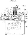
- Fig. 1 to Fig. 3 show an embodiment of the welding apparatus of tubular members according to the present invention.
- this welding apparatus 10 basically includes a pair of holding devices or clamps 16, 18 for clamping respective tubular members 12, 14 made of a thermoplastic resin, for example of a polyarylene sulfide resin or PPS, and a heater 20 disposed between the clamps 16, 18.
- Each clamp 16, 18 has a pair of clamp parts 22a, 22b each composed of a plurality of clamp plates arranged in parallel with each other. V-shape cuts 24a, 24b are formed in side edges opposed to each other, of these clamp parts 22a, 22b.
- the clamp parts 22a, 22b are fixed on sliders 28a, 28b, respectively, set as slidable on a guide rail 26, and thus are arranged as movable toward or away from each other by an appropriate drive device 30.
- the drive devices 30 for clamps 16, 18 are constructed substantially in the same arrangement.
- the drive device 30 is composed basically of a rotatable feed screw 32 meshed with the sliders 28a, 28b and arranged in parallel with a guide rail 26, an electric motor 34, preferably a dc motor, for rotating the feed screw 32, and a driving mechanism, preferably a wrapping connector driving mechanism having a timing belt 36, provided between an end of the feed screw 32 and a rotating shaft of the motor 34.
- the direction of helix in the threaded portion meshed with one slider 28a is opposite to that in the threaded portion meshed with the other slider 28b, and the pitch of the ridges is common to the threaded portions.
- the distance between the sliders 28a, 28b becomes shorter; when the rotating shaft is rotated in the opposite direction, the distance between the sliders 28a, 28b becomes longer.
- clamps 16, 18 are positioned on a base 38 of the welding apparatus 10 so that when the sliders 28a, 28b are moved toward each other to clamp an end portion of a corresponding tubular member 12, 14 between the cuts 24a, 24b of clamp parts 22a, 22b, the tubular members 12, 14 thus clamped are so set as to extend in the horizontal direction and to be aligned on the same axis.
- reference numeral 40 designates a support on which a center portion of a corresponding tubular member 12 or 14 is mounted to be supported horizontally.
- the supports 40 each preferably comprise a support post 42 fixed on the base 38 and a fork member 44 set on the upper end of the support post 42.
- the support post can be vertically extended or contracted, thereby allowing the support post to be changed for different sizes of tubular members to be welded.
- the guide rail 26 and drive device 30 for one clamp 18 are fixed to the base 38 of the welding apparatus 10.
- the tubular member 14 clamped by this clamp 18 is stationary relative to the base 38.
- the guide rail 26 and drive device 30 for the other clamp 16 are fixed on a slider 48 which is arranged to be slidable on the guide rail 46 provided on the base 38.
- the guide rail 46 extends in the same direction as the center axis of the tubular member 12 clamped by the clamp 16.
- the clamp 16 can be moved toward or away from the stationary clamp 18, whereby the end face of the tubular member 12 clamped by the clamp 16 can be brought into contact with the opposed end face of the other tubular member 14 and urged against it.
- the slider 48 is arranged to be movable along the guide rail 46 by an appropriate drive device 50.
- This drive device 50 is provided with an electric motor 52 fixed on the base 38, preferably an ac motor, a dc motor or a stepping motor, and the rotating shaft 54 of the motor 52 extends in parallel with the guide rail 46.
- the rotating shaft 54 is threaded, and a threaded portion thereof is meshed with the slider 48.
- the heater 20 is located between the clamps 16, 18.
- This heater 20 is installed through a support plate 60 on a slider 58 arranged to be slidable on a guide rail 56.
- the guide rail 56 is fixed in position on the base 38 between the clamps 16, 18 and extends in a direction perpendicular to the center axis of the tubular members 12, 14 clamped by the clamps 16, 18.
- a drive device 62 is provided to the slider 58, and thus controlling this drive device 62, the slider 58, in turn the heater 20 can be reciprocated between a heating position between the tubular members 12, 14, and a withdrawn position (the position shown in Fig. 1 and Fig. 3) away from the heating position.
- reference numeral 64 denotes a protection cover for protecting the heater 20 positioned at the withdrawn position.
- the heater 20 comprises a case of a flat plate made for example of a porous ceramic plate, and a heating source such as a nichrome wire enclosed in the case.
- a heating source such as a nichrome wire enclosed in the case.
- the heater 20 is not limited to this arrangement.
- the heating source is not limited to the nichrome wire and the material for the case is not limited to ceramics.
- the heater may be one in which the case and the heating source are cast in an integral manner.
- the opposite surfaces of the heater 20 are heating surfaces for generating heat for melting the end faces 13, 15 of the tubular members 12, 14. When the heater 20 is located at the heating position, each heating surface is opposed to the end faces 13, 15 to be welded, of the corresponding tubular members 12, 14 clamped by the clamps 16, 18.
- the drive device 62 is provided with an electric motor 66 set in the rear portion (a portion on the withdrawn position side of heater 20) in the base 38, preferably an ac motor, a dc motor or a stepping motor with a reduction device.
- a rotating shaft of motor 66 projects from the top surface of base 38 and a pulley 68 is located on the distal end thereof.
- Another pulley 70 is set to be rotatable in the front portion of the top surface of base 38, and a belt 72, preferably a timing belt, is wound between the pulley 70 and the pulley 68 of motor 66.
- Belt 72 extends in parallel along the guide rail 56 and the slider 58 is connected to a part thereof. Accordingly, when the motor 66 is controlled to drive the timing belt 72, the slider 58 can be moved along the guide rail 56.
- the slider 58 is further provided with a spacer 74 of a flat plate for keeping constant the distance between the end faces 13, 15 of the tubular members 12, 14 to be welded upon heating.
- This spacer 74 comprises a spacer main body 76 of a flat plate, and cover plates 78 removably attached to the opposite sides of the spacer main body 76.
- the width of the spacer 74, that is, the distance between the surfaces of the cover plates 78 is larger than the width of the heater 20.
- the welding apparatus 10 is provided with a controller (Fig. 4) 80 for controlling the motors 34, 52, 66 in the drive devices 30, 50, 62.
- the controller 80 is set in the base 38 and is programmed so as to control the respective motors 34, 52, 66 in the manner as described below.
- the controller 80 comprises servo systems for the respective motors 52, 66.
- welding of the tubular members 12, 14 is carried out as follows.
- the tubular member 12 is set on the clamp 16 so that the end face 13 to be welded is in contact with the spacer 74, and a foot switch (Fig. 4) 84 is stepped on.
- the motor 34 for the clamp 16 is actuated to move the clamp parts 22a, 22b of clamp 16 toward each other to clamp the tubular member 12.
- the motor 34 reaches an overloaded state and thus the current supplied to the motor 34 exceeds a predetermined value.
- the controller 80 is so arranged as to detect the amplitude of the current flowing through the motor 34. Judging from the value of the current that the tubular member 12 is clamped, the controller 80 stops the operation of motor 34.
- the tubular member 14 is set on the clamp 18 so that the end face 15 to be welded is in contact with the spacer 74, and the foot switch 84 is again stepped on, thereby clamping the tubular member 14 between the clamp parts 22a, 22b of clamp 18.
- the motor 34 is stopped.
- motor 66 is actuated to set the heater 20 at the heating position between the end faces 13, 15 of the tubular members 12, 14. Since the width of the heater 20 is smaller than the width of the spacer 74, there is a certain clearance formed between each heating surface of heater 20 and the opposed end face 13, 15 of the corresponding tubular member 12, 14.
- the heater 20 After the heater 20 is thus set at the heating position, a current is supplied to the heating source of heater 20, so that the end faces 13, 15 of the tubular members 12, 14 are heated to melt for a predetermined time. After a lapse of the heating time preliminarily determined, the motor 66 is again actuated to move the heater 20 and spacer 74 to the initial withdrawn position, and thereafter this state is maintained. In order to avoid interference of spacer 74 with the tubular members 12, 14 upon the movement to the withdrawn position, the cover plates 78 are preferably removed from the spacer main body 76 before heating or while heating.
- the motor 52 is actuated to move the clamp 16 toward the clamp 18.
- the end face 13 of the tubular member 12 clamped by the clamp 16 comes into contact with the end face 15 of the other tubular member 14, and is further urged against it.
- the motor 66 is controlled to withdraw the heater 20 at a high speed, and the motor 52 is also controlled to move the tubular member 12 at a high speed before the end faces 13, 15 of the tubular members 12, 14 come into contact with each other.
- the tubular member 12 After the end faces 13, 15 of the tubular members 12, 14 come to contact each other, the tubular member 12 is further moved by a predetermined amount, for example by 1.5 mm at a substantially constant speed in the same direction, but the speed of movement is switched to a low speed. After the end faces 13, 15 of the tubular members 12, 14 contact each other, penetration between the end faces 13, 15 effectively proceeds insofar as the moving speed is not too slow. It is also found from experiments that the bead formed in the weld portion is apt to become larger when the end faces 13, 15 of the tubular members 12, 14 are pressed against each other at high speed.
- the speed of the low speed movement is normally set in the range of 0.225 mm/s to 50 mm/s, preferably in the range of 0.225 mm/s to 5 mm/s, more preferably in the range of 0.225 mm/s to 1 mm/s.
- the motor 52 functions as a servo motor, and the movement of tubular members 12, 14 can be pulse-controlled. Specifically, because the distance between the end faces 13, 15 of the tubular members 12, 14 is set to be equal to the width of the spacer 74, the end face 13 of the tubular member 12 can be accurately moved at high speed until the end face 13 comes to contact the end face 15 of the other tubular member 14 without providing special position detecting means, driving the motor 52 with a number of pulses corresponding to the distance or the width As for the movement after contact of the end faces, the motor 52 is driven with a number of pulses corresponding to the amount by which the tubular member 12 is to be moved at the low speed.
- the operation of motor 52 is stopped, and the weld portion is cooled for a predetermined time, for example for 15 to 180 seconds. After the lapse of this cooling time, the motor 34 is reversed to separate the clamp parts 22a, 22b of clamps 16, 18 from each other, thereby releasing the clamping of the tubular members 12, 14. After that, the tubular members 12, 14 thus welded are manually removed from the welding apparatus 10, thus obtaining the desired, welded tubular member.
- a reset switch (Fig. 4) 86 is pressed whereby the motor 52 is again actuated to return the slider 48 to the home position.
- the operation of motor 52 is stopped, whereby the apparatus reaches a standby state for welding of the next new tubular members.
- FIG. 5 to Fig. 7 show a second embodiment of the welding apparatus according to the present invention.
- a welding apparatus 100 of the second embodiment is substantially the same as the welding apparatus 10 of the first embodiment as described above except that the clamps are manually operated and the spacer is manually moved along the guide rail.
- like or corresponding parts to those in the apparatus 10 of the first embodiment are designated by like reference numerals and detailed description thereof is omitted.
- the welding apparatus 100 shown in Fig. 5 to Fig. 7 is illustrated omitting the lower portion of the base 38.
- Each of clamps 102, 104 in the welding apparatus 100 has a lower clamp body 106 and an upper clamp body 108 interconnected as rotatable in the directions R shown in Fig. 7 through a hinge mechanism 110 to the lower clamp body 106.
- the clamps 102, 104 are constructed substantially in the same manner except that the lower clamp body 106 of one clamp 102 is fixed to the slider 48 while the lower clamp body 106 of the other clamp 104 is fixed to the base 38.
- a rectangular cut is formed in the lower clamp body 106 and the upper clamp body 108 in each clamp 102, 104, and adapters 112, 114 are detachably mounted in the cuts.
- These adapters 112, 114 have nearly semi-circular cuts 113, 115 so that a substantially circular hole 116 is formed as shown in Fig. 7.
- the tubular members 12, 14 are set in the hole 116, and the tubular members are clamped between the upper and lower adapters 112, 114 when the upper and lower clamp bodies 106, 108 are closed as shown in Fig. 7.
- the shape and diameter of the hole 116 that is, the shape and the size of the cuts 113, 115 of the adapters 112, 114 are so determined as to be matched with the cross section and the outer diameter of the tubular members to be welded.
- the adapters are exchanged for different adapters matched with the new tubular members.
- the adapters 112, 114 each have screw holes (not shown) of an elongated hole type and screws 118 are put into the screw holes to fix the adapters 112, 114 to the clamp bodies 106, 108.
- each clamp 102, 104 has a lock mechanism for locking and tightening the upper and lower clamp bodies 106, 108 in the closed state shown in Fig. 7.
- the present embodiment employs one comprising a lock rod 122 mounted rotatably in the directions P (Fig. 7) through a pin 120 to the lower clamp body 106 at one end and adapted to fit in recesses (not shown) formed on sides of the upper and lower clamp bodies 106, 108, and a tightening handle 124 meshed with a threaded portion formed at the free end of the lock rod 122.
- the lock rod 122 When the lock rod 122 is brought to an upright posture with the upper clamp body 108 set on the lower clamp body 106, the lock rod 122 fits in the recesses in the clamp bodies 106, 108 and the upper end threaded portion projects upward from the top face of the upper clamp body 108. Then the tightening handle 124 is set to mesh with the threaded portion. On rotating the handle to tighten, the upper and lower clamp bodies 106, 108 are locked tightly with each other and the tubular members 12, 14 between them are also clamped securely.
- a spacer 126 for keeping constant the distance between the end faces 13, 15 of the tubular members 12, 14, is mounted through a support plate 130 to a slider 128.
- This slider 128 is mounted slidably on the guide rail 56 separately and independently of the slider 58 for heater 20. There is no drive device connected to the slider 128, and therefore the movement thereof is effected manually or by the slider 58 for heater 20, as detailed below.
- welding of the tubular members 12, 14 is conducted as follows. First, the spacer 126 is manually moved to be set between the clamps 102, 104. Next, the handle 124 is manually turned to loosen the tightening, and the lock rod 122 is rotated to be taken out of the recesses in the clamp bodies 106, 108, thereby releasing the lock of the clamp bodies 106, 108. Then the upper clamp body 108 is rotated away from the lower clamp body 106, and the end portion of the tubular member 12, 14 is set in the cut 103 of the adapter 112 on the lower clamp body 106.
- the positions of the tubular members 12, 14 are adjusted so that the end faces 13, 15 of the tubular members 12, 14 come to contact the spacer 126.
- the upper clamp body 108 is rotated in the reverse direction to pinch the tubular member 12, 14 between the upper and lower clamp bodies 106, 108.
- the lock rod 122 is rotated to fit in the recesses in the clamp bodies 106, 108 and the handle 124 is turned to tighten, whereby the tubular members 12, 14 are clamped tightly between the clamp bodies 106, 108.
- the start switch is pressed, so that the controller actuates the motor 66' to set the heater 20 at the heating position between the clamps 102, 104.
- the slider 58 for the heater 20 pushes the slider 128 for the spacer 126 so as to return the spacer 126 to the home position away from the space between the clamps 102, 104.
- the spacer 126 does not pass between the tubular members 12, 14 after the end faces 13, 15 of the tubular members 12, 14 are heated to melt, and therefore the second embodiment obviates the cover plates 78 of the spacer 74 in the first embodiment, thus requiring no time and labor for removing the cover plates 78.
Landscapes
- Engineering & Computer Science (AREA)
- Mechanical Engineering (AREA)
- Physics & Mathematics (AREA)
- Health & Medical Sciences (AREA)
- Electromagnetism (AREA)
- Toxicology (AREA)
- Lining Or Joining Of Plastics Or The Like (AREA)
Applications Claiming Priority (2)
| Application Number | Priority Date | Filing Date | Title |
|---|---|---|---|
| JP14787/94 | 1994-01-13 | ||
| JP1478794 | 1994-01-13 |
Publications (2)
| Publication Number | Publication Date |
|---|---|
| EP0663279A2 true EP0663279A2 (de) | 1995-07-19 |
| EP0663279A3 EP0663279A3 (de) | 1996-08-21 |
Family
ID=11870773
Family Applications (1)
| Application Number | Title | Priority Date | Filing Date |
|---|---|---|---|
| EP95300157A Withdrawn EP0663279A3 (de) | 1994-01-13 | 1995-01-11 | Verfahren zum Verschweissen von rohrförmigen Teilen. |
Country Status (1)
| Country | Link |
|---|---|
| EP (1) | EP0663279A3 (de) |
Cited By (4)
| Publication number | Priority date | Publication date | Assignee | Title |
|---|---|---|---|---|
| WO1996015898A1 (de) * | 1994-11-21 | 1996-05-30 | Ulrike Richter | Vorrichtung zum stumpfschweissen von rohren aus thermoplastischem kunststoff |
| EP1136234A1 (de) * | 2000-03-23 | 2001-09-26 | Urban GmbH & Co. Maschinenbau KG | Verfahren und Vorrichtung zum Verschweissen von Kunststoffprofilstäben |
| WO2018076400A1 (zh) * | 2016-10-28 | 2018-05-03 | 南通宝田包装科技有限公司 | 一种智能型塑料管成型机 |
| WO2023061594A1 (de) * | 2021-10-14 | 2023-04-20 | Huerner Schweisstechnik GmbH | SCHWEIßMASCHINE UND VERFAHREN ZUR HERSTELLUNG EINER STUMPFSCHWEIßVERBINDUNG |
Family Cites Families (10)
| Publication number | Priority date | Publication date | Assignee | Title |
|---|---|---|---|---|
| SU448139A1 (ru) * | 1969-04-18 | 1975-08-05 | Э. А. Вендэ | Устройство дл стыковой сварки термопластических труб |
| JPS5836409A (ja) * | 1981-08-26 | 1983-03-03 | Mitsubishi Chem Ind Ltd | 熱可塑性合成樹脂成形品の溶着方法及び装置 |
| SU1175730A1 (ru) * | 1983-07-07 | 1985-08-30 | Inst Elektroswarki Patona | "уctpoйctbo для kohtaktho-teплoboй cbapkи плactmaccobыx tpуб" |
| JPS6194741A (ja) * | 1984-10-17 | 1986-05-13 | Retsukisu Kogyo Kk | 樹脂管用バツト融着機 |
| GB8615517D0 (en) * | 1986-06-25 | 1986-07-30 | Fusion Equipment Ltd | Butt-welding of pipes |
| US4793880A (en) * | 1987-05-18 | 1988-12-27 | Denco, Inc. | Sterile welding of plastic tubes |
| JPH02107429A (ja) * | 1988-10-17 | 1990-04-19 | Nippon Pillar Packing Co Ltd | 溶融合成樹脂管の溶着装置 |
| US5279685A (en) * | 1990-08-20 | 1994-01-18 | Denco, Inc. | Total containment device for connect/disconnect of plastic tubes |
| US5328541A (en) * | 1991-12-11 | 1994-07-12 | Kureha Kagaku Kogyo Kabushiki Kaisha | Method of welding tubular products of polyarylene sulfide and welded tubular structure |
| JPH05193004A (ja) * | 1992-01-17 | 1993-08-03 | Kureha Chem Ind Co Ltd | 合成樹脂製管の突合せ溶接装置 |
-
1995
- 1995-01-11 EP EP95300157A patent/EP0663279A3/de not_active Withdrawn
Cited By (4)
| Publication number | Priority date | Publication date | Assignee | Title |
|---|---|---|---|---|
| WO1996015898A1 (de) * | 1994-11-21 | 1996-05-30 | Ulrike Richter | Vorrichtung zum stumpfschweissen von rohren aus thermoplastischem kunststoff |
| EP1136234A1 (de) * | 2000-03-23 | 2001-09-26 | Urban GmbH & Co. Maschinenbau KG | Verfahren und Vorrichtung zum Verschweissen von Kunststoffprofilstäben |
| WO2018076400A1 (zh) * | 2016-10-28 | 2018-05-03 | 南通宝田包装科技有限公司 | 一种智能型塑料管成型机 |
| WO2023061594A1 (de) * | 2021-10-14 | 2023-04-20 | Huerner Schweisstechnik GmbH | SCHWEIßMASCHINE UND VERFAHREN ZUR HERSTELLUNG EINER STUMPFSCHWEIßVERBINDUNG |
Also Published As
| Publication number | Publication date |
|---|---|
| EP0663279A3 (de) | 1996-08-21 |
Similar Documents
| Publication | Publication Date | Title |
|---|---|---|
| US5241157A (en) | Arrangement for butt-welding plastic material components | |
| EP0546551B1 (de) | Verfahren zum Erstellen einer Verbindung zwischen einer Hauptleitung und einem Abzweigrohr | |
| DE4013471C2 (de) | ||
| EP0953431B1 (de) | Rohrverbindungsvorrichtung | |
| CA2760914C (en) | Tube-joining apparatus and tube-joining method | |
| EP0483478A2 (de) | Schweissen von Kunststoffrohren unter hermetischen Abschluss | |
| US5256229A (en) | Sterile containment welding device for plastic tubes | |
| JP2009514689A (ja) | パイプ切断装置 | |
| EP0602960B1 (de) | Vorrichtung zum Stumpfschweissen von Kunststoffrohren | |
| US6550514B1 (en) | Indexer system for use with a plastic pipe butt-fusion machine | |
| EP0663279A2 (de) | Verfahren zum Verschweissen von rohrförmigen Teilen | |
| US5632845A (en) | Method for welding tubular parts | |
| JPH07241913A (ja) | 管状部材の溶着方法及び装置 | |
| JPH08309862A (ja) | プラスチックチューブの無菌連結/切り離し用装置 | |
| JPH1177834A (ja) | 熱可塑性樹脂配管材用融着機 | |
| EP0480613A2 (de) | Verfahren und Vorrichtung zum Schweissen eines Bandes durch Bandüberlappungen | |
| JPH08156102A (ja) | 熱溶着可能な樹脂製管状部品の自動溶着装置 | |
| EP0662390A2 (de) | Einrichtung und Verfahren zum Verschweigen von Teilen aus thermoplastischem Material | |
| JP3157069B2 (ja) | 融着機 | |
| JPH1016060A (ja) | 熱溶着可能な樹脂製管状部品の携帯型自動溶着装置 | |
| CN119080385B (zh) | 一种智能石英棒焊接机及其控制方法 | |
| JP3608467B2 (ja) | 熱可塑性樹脂管の圧接接合用平板 | |
| JP3157064B2 (ja) | 融着機 | |
| US5656114A (en) | Ribbon overlap welding system | |
| JPH0639969Y2 (ja) | 回転式樹脂溶接機 |
Legal Events
| Date | Code | Title | Description |
|---|---|---|---|
| PUAI | Public reference made under article 153(3) epc to a published international application that has entered the european phase |
Free format text: ORIGINAL CODE: 0009012 |
|
| AK | Designated contracting states |
Kind code of ref document: A2 Designated state(s): AT DE FR GB |
|
| RIN1 | Information on inventor provided before grant (corrected) |
Inventor name: USUI, SATOSHI C/O NISHIKI RESEARCH LAB. OF KUREHA Inventor name: YAMANOBE, YOUICHIROU, C/O NISHIKI RES. LAB. |
|
| PUAL | Search report despatched |
Free format text: ORIGINAL CODE: 0009013 |
|
| AK | Designated contracting states |
Kind code of ref document: A3 Designated state(s): AT DE FR GB |
|
| STAA | Information on the status of an ep patent application or granted ep patent |
Free format text: STATUS: THE APPLICATION IS DEEMED TO BE WITHDRAWN |
|
| 18D | Application deemed to be withdrawn |
Effective date: 19970222 |