EP0663290B1 - Entraínement pour un dispositif de raclage à mouvement alternatif transversal - Google Patents
Entraínement pour un dispositif de raclage à mouvement alternatif transversal Download PDFInfo
- Publication number
- EP0663290B1 EP0663290B1 EP95100294A EP95100294A EP0663290B1 EP 0663290 B1 EP0663290 B1 EP 0663290B1 EP 95100294 A EP95100294 A EP 95100294A EP 95100294 A EP95100294 A EP 95100294A EP 0663290 B1 EP0663290 B1 EP 0663290B1
- Authority
- EP
- European Patent Office
- Prior art keywords
- drive according
- doctor blade
- working cylinder
- reciprocating
- computer
- Prior art date
- Legal status (The legal status is an assumption and is not a legal conclusion. Google has not performed a legal analysis and makes no representation as to the accuracy of the status listed.)
- Expired - Lifetime
Links
- 238000010168 coupling process Methods 0.000 claims description 9
- 230000008878 coupling Effects 0.000 claims description 8
- 238000005859 coupling reaction Methods 0.000 claims description 8
- 238000006073 displacement reaction Methods 0.000 claims description 3
- 230000001419 dependent effect Effects 0.000 claims description 2
- 238000005259 measurement Methods 0.000 claims 2
- 239000000969 carrier Substances 0.000 claims 1
- 230000001360 synchronised effect Effects 0.000 claims 1
- 238000007774 anilox coating Methods 0.000 description 6
- 238000010586 diagram Methods 0.000 description 3
- 230000002411 adverse Effects 0.000 description 1
- 230000000694 effects Effects 0.000 description 1
- 239000003999 initiator Substances 0.000 description 1
- 239000002184 metal Substances 0.000 description 1
- 238000000034 method Methods 0.000 description 1
- 239000000523 sample Substances 0.000 description 1
- 230000001960 triggered effect Effects 0.000 description 1
Images

Classifications
-
- B—PERFORMING OPERATIONS; TRANSPORTING
- B41—PRINTING; LINING MACHINES; TYPEWRITERS; STAMPS
- B41F—PRINTING MACHINES OR PRESSES
- B41F9/00—Rotary intaglio printing presses
- B41F9/06—Details
- B41F9/08—Wiping mechanisms
- B41F9/10—Doctors, scrapers, or like devices
- B41F9/1009—Doctors, scrapers, or like devices with reciprocating movement
Definitions
- the invention relates to a drive for an oscillating doctor device according to the preamble of claim 1.
- a mechanical doctor blade drive is known (DE 32 47 679 A1), in which the Traversing movement by a circumferentially driven one circumferential, axially deflected with respect to a radial plane, into the a sliding block against twisting connected to the squeegee secured bush engages, equipped spindle is generated.
- the mechanical squeegee drive is at risk of wear due to the sliding connection and inevitably with a wear dependent, itself especially in the reversal points of the squeegee due to its extended standstill game with negative effects on the squeegee process. Furthermore the reversal points are always in the same place, so both increased squeegee wear and scoring on the roller to be inked are favored.
- the squeegee drive takes place via a shaft on the two Couplings attached with counter-rotating drive wheels are, which are alternately coupled to a drive wheel, the Direction of rotation of the drive wheels is opposite.
- the wave owns at the other end a transport thread, which has a coupling bush is connected to a squeegee holder.
- the size of the squeegee stroke can also be adjusted in this solution, however, the reversal points are always present after the respective setting the same place.
- DE-B-10 38 066 shows a hydraulic doctor drive, in which the Reversal triggered by stops carried during the squeegee movement becomes.
- the effective position of the stops can be changed with cams and thereby the amplitude of the doctor stroke can be trimmed symmetrically in a sinusoidal manner.
- FR-A-2 284 451 provides a hydraulic traversing drive for a distribution roller an inking unit.
- a programmable controller By means of a programmable controller, reference is made to the angular position of the impression cylinder the speed curve of the Axial movement of the roller is controlled to increase the amount of ink transferred influence.
- the invention has for its object a drive for an iridescent Squeegee device according to the preamble of claim 1 to provide the largely a constant squeegee movement in the entire stroke range, a change of direction with minimal standstill and a stepless one Adjustment of the speed - possibly depending on the machine speed - as well as a reversal of the squeegee movement realized.
- the invention ensures that the other requirements are met the task above all with relatively little effort a constant reversal point shift for the squeegee movement, so that in connection with the almost non-stop reversal of direction local squeegee wear and damage to the surface of the anilox roller in the form of grooves are avoided, which increases the service life of squeegees and Anilox roller increased to save costs.
- This can be used for tax transactions adverse cycle time of the computer in an advantageous manner for an additional Relocation of the reversal points of the squeegee movement can be used.
- a hydraulic servo valve is used to control the working cylinder Particularly suitable as it has particularly low traversing speeds are functionally reliable.
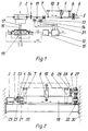
- Fig. 1 shows an axially parallel to an anilox roller, not shown mounted doctor blade 1, with which the piston rod 2 one working cylinder 3 in which can be pressurized on both sides Traversing direction is fixedly connected by means of coupling 4.
- the doctor blade carrier 1 has an anti-rotation device 6 and 6 guided in the frame 5 Holder 7; 8 for a working cylinder 9 operated by a pressure medium doctor blade holder which can be pivoted to the anilox roller relative to the doctor blade carrier 1 10th
- the doctor blade 1 is with a position sensor 11 for two fixed to the frame a computer 12 connected sensors 13; 14 equipped.
- the computer 12 is with a control unit 15 for in the pressure medium lines 16; 17 for the working cylinder 3 intermediate servo valve 18 coupled.
- FIG. 2 shows a schematic representation of a solution designed according to FIG. 1, in which the squeegee is slidable in the form of a traversing shaft 19 on a cross member 20 fixed bearings 21; 22 stored and the working cylinder 3 aligned with its piston rod 2 coaxial to the traversing shaft 19 via the coupling 4 with the latter firmly connected to the cross member 20th is attached, the coupling 4 of two each separately on the Piston rod 2 or the traversing shaft 19 fastened axially to one another screwed drive plates 23; 24 exists.
- an elastically deformable disk 25 can be arranged.
- the cross member 20 between the frame walls 29; 30 of Frame is firmly screwed to it, this can also be used as a Cross member fixed between two pivoting the entire doctor device from the anilox roller, each pivotable in the frame walls 29; 30 mounted holders can be arranged.
- the computer 12 which can also be integrated into a printing unit computer, for example, has the traversing speed v as an adjustable input variable, which may also be linked to the machine speed, and the control unit 15 connected to the computer, in addition to the traversing speed v, has the time t as output variables for the servo valve 18 , since within the by the sensors 13; 14 limited stroke range H from the working cylinder 3 to the direction reversal by the respective sensor 13; 14 partial stroke ranges T, which are continuously displaced in the same direction, including the associated reverse traversing movement T c shortened by the offset T v , are permanently programmed in the computer (FIG. 3). This means that with an increase in the traversing speed and thus the lifting speed of the working cylinder, the time for the latter to be pressurized is inevitably shortened.
- a technically more complex control of the doctor carrier movement is instead of the sensors 13; 14 in Fig. 1 a dash-dotted, the computer over the entire stroke range H of the working cylinder 3 path impulses 31 to arrange, whereby the sub-areas T 1 to T 6 , including the associated retrograde traversing movements T c1 to T c5 , according to FIG. 5 different can be designed.
Landscapes
- Engineering & Computer Science (AREA)
- Mechanical Engineering (AREA)
- Inking, Control Or Cleaning Of Printing Machines (AREA)
Claims (14)
- Dispositif d'entraínement pour un dispositif à racle à déplacement alternatif pour des cylindres tramés en tant que cylindres encreurs ou cylindres porte-plaques de presses rotatives à imprimer, comportant un support de racle qui est disposé de manière à être déplaçable parallèlement à l'axe du cylindre tramé et est actionné par un vérin hydraulique pouvant être alimenté des deux côtés par un fluide sous pression au moyen d'une soupape commandée, caractérisé en ce que deux capteurs (13 ; 14) sont couplés à un calculateur (12) qui, au moyen d'une unité de commande (15), commande une soupape de commande de débit en subdivisant la gamme de course de déplacement (H) du vérin hydraulique (3), qui est limitée par les capteurs (13 ; 14), en plusieurs gammes de courses partielles de déplacement (T) qui sont décalées respectivement d'une manière continue dans la même direction jusqu'au capteur respectif (13 ; 14), qui réalise une inversion de direction, le déplacement respectif de retour (Tc) lors du déplacement alternatif étant réduit à un décalage (Tv) dans la gamme de course partielle de déplacement (T).
- Dispositif d'entraínement pour un dispositif à racle à déplacement alternatif pour des cylindres tramés en tant que cylindres encreurs ou cylindres porte-plaques de presses rotatives à imprimer, comportant un support de racle (1) qui est disposé de manière à être déplaçable parallèlement à l'axe du cylindre tramé et est actionné par un vérin hydraulique (3) alimenté des deux côtés par un fluide sous pression au moyen d'une soupape commandée (18), caractérisé en ce qu'un dispositif de mesure de déplacement (31) pour la course de déplacement (H) du vérin hydraulique (3) est couplé à un calculateur (12) qui, au moyen d'une unité de commande (15), commande, conformément à un programme, une soupape de commande de débit en subdivisant en des gammes de courses partielles de déplacement (T1 à T6) pouvant être configurées à volonté, la gamme de course de déplacement prévue (H) du vérin hydraulique (3) en ce qui concerne le déplacement alternatif dans les deux sens.
- Dispositif d'entraínement selon la revendication 1 ou 2, caractérisé en ce que la soupape de commande de débit est une servosoupape hydraulique (18).
- Dispositif d'entraínement selon la revendication 1, caractérisé en ce que le point respectif de rebroussement (U1' à U6') du déplacement alternatif est décalé d'une manière aléatoire au cours de la durée du cycle du calculateur (12).
- Dispositif d'entraínement selon les revendications 1 à 4, caractérisé en ce que la vitesse (V) du déplacement alternatif est réglable en tant que grandeur d'entrée variable du calculateur (12).
- Dispositif d'entraínement selon la revendication 1 ou 2, caractérisé en ce que le calculateur (12) est relié, de manière à les commander, à plusieurs supports (1) de racles, dont les déplacements alternatifs sont synchrones.
- Dispositif d'entraínement selon la revendications 1 à 6, caractérisé en ce que le vérin hydraulique (3) est fixé par sa tige de piston (2) au support de racle (1) monté de manière à être déplacable, et est disposé conjointement avec ce support sur un support transversal.
- Dispositif d'entraínement selon la revendication 7, caractérisé en ce que le support transversal est constitué par une traverse (20) qui est disposée entre les parois (29 ; 30) du châssis et est fixée à ces parois.
- Dispositif d'entraínement selon la revendication 7, caractérisé en ce que le support transversal est disposé entre deux appuis montés de manière à pouvoir pivoter respectivement dans les parois (29 ; 30) du châssis, en étant solidement fixé à ces appuis.
- Dispositif d'entraínement selon les revendications 1 à 6, caractérisé en ce que le vérin hydraulique (3) et le support de racle (1) sont disposés ou montés, en étant alignés dans la direction du déplacement alternatif, sur des consoles fixées respectivement intérieurement des deux côtés sur les parois (29 ; 30) du châssis.
- Dispositif d'entraínement selon les revendications 1 à 10, caractérisé en ce que la tige de piston (2) du vérin hydraulique (3) est reliée axialement, sans jeu, au support de racle (1) au moyen d'un accouplement (4).
- Dispositif d'entraínement selon la revendication 11, caractérisé en ce que l'accouplement (4) est constitué de deux disques d'entraínement (23 ; 24), vissés l'un à l'autre et fixés sur la tige de piston (2) ou sur le support de racle (1) agencé de préférence sous la forme d'un arbre (19) de déplacement alternatif.
- Dispositif d'entraínement selon la revendication 12, caractérisé en ce qu'entre les disques d'entraínement (23 ; 24) est disposé un disque déformable élastiquement (25), qui compense un faible décalage entre l'axe de la tige de piston (2) et l'axe de l'arbre de déplacement alternatif (19).
- Dispositif d'entraínement selon l'une des revendications 1 à 13, caractérisé en ce que les capteurs (13 ; 14) ou le dispositif de mesure de déplacement sont solidaires du châssis, et un transmetteur de position (11) est disposé de manière à exécuter le déplacement de va-et-vient.
Applications Claiming Priority (2)
| Application Number | Priority Date | Filing Date | Title |
|---|---|---|---|
| DE4401328A DE4401328A1 (de) | 1994-01-18 | 1994-01-18 | Antrieb für eine changierende Rakelvorrichtung |
| DE4401328 | 1994-01-18 |
Publications (2)
| Publication Number | Publication Date |
|---|---|
| EP0663290A1 EP0663290A1 (fr) | 1995-07-19 |
| EP0663290B1 true EP0663290B1 (fr) | 1998-08-12 |
Family
ID=6508166
Family Applications (1)
| Application Number | Title | Priority Date | Filing Date |
|---|---|---|---|
| EP95100294A Expired - Lifetime EP0663290B1 (fr) | 1994-01-18 | 1995-01-11 | Entraínement pour un dispositif de raclage à mouvement alternatif transversal |
Country Status (2)
| Country | Link |
|---|---|
| EP (1) | EP0663290B1 (fr) |
| DE (2) | DE4401328A1 (fr) |
Families Citing this family (5)
| Publication number | Priority date | Publication date | Assignee | Title |
|---|---|---|---|---|
| DE50309331D1 (de) * | 2003-11-14 | 2008-04-17 | Fischer & Krecke Gmbh & Co | Verfahren und Vorrichtung zum Verschieben eines Rakelmessers |
| DE102005061915A1 (de) * | 2005-12-23 | 2007-07-05 | Koenig & Bauer Aktiengesellschaft | Verfahren zum Betreiben eines Kurzfarbwerkes und Einrichtung zu diesem Zweck |
| CN103240963A (zh) * | 2013-05-31 | 2013-08-14 | 昆山欧莱特印刷机械工业有限公司 | 一种智能油墨刮刀系统 |
| CN108909180B (zh) * | 2018-06-28 | 2023-10-17 | 河南宝钢制罐有限公司 | 金属罐印刷机的油墨单元用传墨分割辊测试系统及方法 |
| DE102019103790A1 (de) * | 2019-02-05 | 2020-08-06 | Koenig & Bauer Ag | Druckwerk und Druckmaschine mit einem Druckwerk |
Family Cites Families (9)
| Publication number | Priority date | Publication date | Assignee | Title |
|---|---|---|---|---|
| DE512135C (de) * | 1928-11-17 | 1932-02-26 | Johannisberg G M B H Maschf | Vorrichtung zum Laengsbewegen der Rakel an Rotationstiefdruckmaschinen |
| US2447090A (en) * | 1944-01-14 | 1948-08-17 | Goss Printing Press Co Ltd | Rotary intaglio printing press |
| DE1038066B (de) * | 1955-05-09 | 1958-09-04 | Koenig & Bauer Schnellpressfab | Hydraulischer Antrieb fuer die Rakel bei Tiefdruckmaschinen |
| DE1933838A1 (de) * | 1969-07-03 | 1971-02-04 | Windmoeller & Hoelscher | Rakelvorrichtung fuer Tiefdruckmaschinen |
| CH551868A (de) * | 1972-05-12 | 1974-07-31 | Frankenthal Ag Albert | Rakelvorrichtung an tiefdruck-rotationsmaschine. |
| DE2443504C3 (de) * | 1974-09-11 | 1978-11-23 | Roland Offsetmaschinenfabrik Faber & Schleicher Ag, 6050 Offenbach | Farbwerk an Druckmaschinen |
| US4398463A (en) * | 1981-08-19 | 1983-08-16 | Motter Printing Press Co. | Non-repeat doctor blade drive |
| DE3220845C2 (de) * | 1982-06-03 | 1985-02-21 | M.A.N.- Roland Druckmaschinen AG, 6050 Offenbach | Antrieb einer Rakeleinrichtung |
| DE3247679A1 (de) * | 1982-12-23 | 1984-07-05 | Albert-Frankenthal Ag, 6710 Frankenthal | Rakelantrieb |
-
1994
- 1994-01-18 DE DE4401328A patent/DE4401328A1/de not_active Withdrawn
-
1995
- 1995-01-11 EP EP95100294A patent/EP0663290B1/fr not_active Expired - Lifetime
- 1995-01-11 DE DE59503099T patent/DE59503099D1/de not_active Expired - Fee Related
Also Published As
| Publication number | Publication date |
|---|---|
| EP0663290A1 (fr) | 1995-07-19 |
| DE4401328A1 (de) | 1995-07-20 |
| DE59503099D1 (de) | 1998-09-17 |
Similar Documents
| Publication | Publication Date | Title |
|---|---|---|
| EP1277575B1 (fr) | Presse d'impression offset | |
| EP0813959B1 (fr) | Cylindre entraíné | |
| EP1040917B1 (fr) | Procédé et dispositif à compensation de vibrations torsionelles d'une machine à imprimer | |
| EP0663290B1 (fr) | Entraínement pour un dispositif de raclage à mouvement alternatif transversal | |
| DE3344777C1 (de) | Feuchtmitteldosiervorrichtung für das Feuchtwerk einer Druckmaschine | |
| DE2031504A1 (de) | Druckerpresse | |
| WO2007128709A2 (fr) | Rouleau d'une machine à imprimer comportant un dispositif conçu pour animer le rouleau rotatif d'un mouvement oscillant axial | |
| EP0267504B1 (fr) | Palier pour rouleaux applicateurs à mouvement de va-et-vient dans les machines d'impression | |
| DE3028406A1 (de) | Vorrichtung zum axialen hin- und herbewegen von reibwalzen im farbwerk von druckmaschinen | |
| DE2822043C3 (de) | Einteiliger Greifer eines Zylinders einer Rotationsdruckmaschine | |
| DE10011429B4 (de) | Druckmaschine mit einer Reinigungseinrichtung zur Reinigung zweier Druckmaschinenzylinder | |
| EP0803720A2 (fr) | Station de mesure du balourd | |
| DE3327872A1 (de) | Farbwerk, insbesondere zur anwendung bei tubenbedruckmaschinen | |
| DE4214210C2 (de) | Kurbelbetrieb für eine Druckmaschine | |
| DE10003026B4 (de) | Antrieb für eine Reibwalze | |
| DE4141126B4 (de) | Farbheberantrieb für Druckmaschinen | |
| CH452551A (de) | Rotationsdruckmaschine für direkten und indirekten Druck | |
| DE1003760B (de) | Walzensupport fuer das Lagern von Farbwerkwalzen an Buchdruck-, Offsetdruck- u. dgl.Maschinen | |
| DE4214709C2 (de) | Verreibhubantrieb für Reibzylinder | |
| EP1256447A2 (fr) | Tambour d'accumulation dans les dispositifs de retournement des machines à imprimer | |
| EP1254025B1 (fr) | Systeme de guidage pour machines d'impression de feuilles de tole et machines de laquage de feuilles de tole | |
| DE970481C (de) | Rakelvorrichtung fuer Tiefdruckmaschinen | |
| DD285051A5 (de) | Heberfarbwerk fuer rotationsdruckmaschinen | |
| DE102005031569B4 (de) | Druckmaschine | |
| EP0387484B1 (fr) | Dispositif supplémentaire pour un groupe de mouillage d'une machine d'impression offset |
Legal Events
| Date | Code | Title | Description |
|---|---|---|---|
| PUAI | Public reference made under article 153(3) epc to a published international application that has entered the european phase |
Free format text: ORIGINAL CODE: 0009012 |
|
| AK | Designated contracting states |
Kind code of ref document: A1 Designated state(s): CH DE FR GB IT LI SE |
|
| 17P | Request for examination filed |
Effective date: 19951230 |
|
| 17Q | First examination report despatched |
Effective date: 19961216 |
|
| GRAG | Despatch of communication of intention to grant |
Free format text: ORIGINAL CODE: EPIDOS AGRA |
|
| GRAG | Despatch of communication of intention to grant |
Free format text: ORIGINAL CODE: EPIDOS AGRA |
|
| GRAH | Despatch of communication of intention to grant a patent |
Free format text: ORIGINAL CODE: EPIDOS IGRA |
|
| GRAH | Despatch of communication of intention to grant a patent |
Free format text: ORIGINAL CODE: EPIDOS IGRA |
|
| GRAA | (expected) grant |
Free format text: ORIGINAL CODE: 0009210 |
|
| ITF | It: translation for a ep patent filed | ||
| AK | Designated contracting states |
Kind code of ref document: B1 Designated state(s): CH DE FR GB IT LI SE |
|
| REG | Reference to a national code |
Ref country code: CH Ref legal event code: NV Representative=s name: E. BLUM & CO. PATENTANWAELTE Ref country code: CH Ref legal event code: EP |
|
| REF | Corresponds to: |
Ref document number: 59503099 Country of ref document: DE Date of ref document: 19980917 |
|
| GBT | Gb: translation of ep patent filed (gb section 77(6)(a)/1977) |
Effective date: 19981104 |
|
| ET | Fr: translation filed | ||
| PGFP | Annual fee paid to national office [announced via postgrant information from national office to epo] |
Ref country code: GB Payment date: 19981211 Year of fee payment: 5 |
|
| PGFP | Annual fee paid to national office [announced via postgrant information from national office to epo] |
Ref country code: FR Payment date: 19981215 Year of fee payment: 5 |
|
| PGFP | Annual fee paid to national office [announced via postgrant information from national office to epo] |
Ref country code: DE Payment date: 19981217 Year of fee payment: 5 |
|
| PGFP | Annual fee paid to national office [announced via postgrant information from national office to epo] |
Ref country code: SE Payment date: 19981223 Year of fee payment: 5 |
|
| PGFP | Annual fee paid to national office [announced via postgrant information from national office to epo] |
Ref country code: CH Payment date: 19981229 Year of fee payment: 5 |
|
| PLBE | No opposition filed within time limit |
Free format text: ORIGINAL CODE: 0009261 |
|
| STAA | Information on the status of an ep patent application or granted ep patent |
Free format text: STATUS: NO OPPOSITION FILED WITHIN TIME LIMIT |
|
| 26N | No opposition filed | ||
| PG25 | Lapsed in a contracting state [announced via postgrant information from national office to epo] |
Ref country code: GB Free format text: LAPSE BECAUSE OF NON-PAYMENT OF DUE FEES Effective date: 20000111 |
|
| PG25 | Lapsed in a contracting state [announced via postgrant information from national office to epo] |
Ref country code: SE Free format text: LAPSE BECAUSE OF NON-PAYMENT OF DUE FEES Effective date: 20000112 |
|
| PG25 | Lapsed in a contracting state [announced via postgrant information from national office to epo] |
Ref country code: LI Free format text: LAPSE BECAUSE OF NON-PAYMENT OF DUE FEES Effective date: 20000131 Ref country code: CH Free format text: LAPSE BECAUSE OF NON-PAYMENT OF DUE FEES Effective date: 20000131 |
|
| GBPC | Gb: european patent ceased through non-payment of renewal fee |
Effective date: 20000111 |
|
| EUG | Se: european patent has lapsed |
Ref document number: 95100294.8 |
|
| REG | Reference to a national code |
Ref country code: CH Ref legal event code: PL |
|
| PG25 | Lapsed in a contracting state [announced via postgrant information from national office to epo] |
Ref country code: FR Free format text: LAPSE BECAUSE OF NON-PAYMENT OF DUE FEES Effective date: 20000929 |
|
| PG25 | Lapsed in a contracting state [announced via postgrant information from national office to epo] |
Ref country code: DE Free format text: LAPSE BECAUSE OF NON-PAYMENT OF DUE FEES Effective date: 20001101 |
|
| REG | Reference to a national code |
Ref country code: FR Ref legal event code: ST |
|
| PG25 | Lapsed in a contracting state [announced via postgrant information from national office to epo] |
Ref country code: IT Free format text: LAPSE BECAUSE OF NON-PAYMENT OF DUE FEES;WARNING: LAPSES OF ITALIAN PATENTS WITH EFFECTIVE DATE BEFORE 2007 MAY HAVE OCCURRED AT ANY TIME BEFORE 2007. THE CORRECT EFFECTIVE DATE MAY BE DIFFERENT FROM THE ONE RECORDED. Effective date: 20050111 |