EP0663314A1 - Verriegelungsvorrichtung - Google Patents
Verriegelungsvorrichtung Download PDFInfo
- Publication number
- EP0663314A1 EP0663314A1 EP94309129A EP94309129A EP0663314A1 EP 0663314 A1 EP0663314 A1 EP 0663314A1 EP 94309129 A EP94309129 A EP 94309129A EP 94309129 A EP94309129 A EP 94309129A EP 0663314 A1 EP0663314 A1 EP 0663314A1
- Authority
- EP
- European Patent Office
- Prior art keywords
- locking device
- rollers
- accordance
- tapering
- roller
- Prior art date
- Legal status (The legal status is an assumption and is not a legal conclusion. Google has not performed a legal analysis and makes no representation as to the accuracy of the status listed.)
- Withdrawn
Links
Images

Classifications
-
- B—PERFORMING OPERATIONS; TRANSPORTING
- B60—VEHICLES IN GENERAL
- B60N—SEATS SPECIALLY ADAPTED FOR VEHICLES; VEHICLE PASSENGER ACCOMMODATION NOT OTHERWISE PROVIDED FOR
- B60N2/00—Seats specially adapted for vehicles; Arrangement or mounting of seats in vehicles
- B60N2/02—Seats specially adapted for vehicles; Arrangement or mounting of seats in vehicles the seat or part thereof being movable, e.g. adjustable
- B60N2/04—Seats specially adapted for vehicles; Arrangement or mounting of seats in vehicles the seat or part thereof being movable, e.g. adjustable the whole seat being movable
- B60N2/06—Seats specially adapted for vehicles; Arrangement or mounting of seats in vehicles the seat or part thereof being movable, e.g. adjustable the whole seat being movable slidable
- B60N2/07—Slide construction
- B60N2/0702—Slide construction characterised by its cross-section
- B60N2/0717—Rounded, e.g. circular
-
- F—MECHANICAL ENGINEERING; LIGHTING; HEATING; WEAPONS; BLASTING
- F16—ENGINEERING ELEMENTS AND UNITS; GENERAL MEASURES FOR PRODUCING AND MAINTAINING EFFECTIVE FUNCTIONING OF MACHINES OR INSTALLATIONS; THERMAL INSULATION IN GENERAL
- F16B—DEVICES FOR FASTENING OR SECURING CONSTRUCTIONAL ELEMENTS OR MACHINE PARTS TOGETHER, e.g. NAILS, BOLTS, CIRCLIPS, CLAMPS, CLIPS OR WEDGES; JOINTS OR JOINTING
- F16B7/00—Connections of rods or tubes, e.g. of non-circular section, mutually, including resilient connections
- F16B7/10—Telescoping systems
- F16B7/14—Telescoping systems locking in intermediate non-discrete positions
- F16B7/1409—Telescoping systems locking in intermediate non-discrete positions with balls or rollers urged by an axial displacement of a wedge or a conical member
Definitions
- This invention relates to a locking device, and in particular to a locking device for a seat slide assembly capable of preventing movement of the seat in a fore-and-aft direction once its position has been chosen by the seat occupant.
- a vehicle seat slide assembly such as that provided to allow the fore-and-aft adjustment of a vehicle seat typically comprises a first elongated slide member adapted to be fixed to the vehicle floor and a second elongated slide member adapted to be attached to and carry the vehicle seat, the second member being slidably engaged with the first member. Bearings are provided between the two members to assist sliding. Conventionally two assemblies are provided, one on each side of the seat.
- GB Patents 772203 and 1067133, and Published European Application No. 540252 each describe a locking device for locking a member longitudinally with respect to a tube or rod having a circular cross-section outer surface, comprising a pair of tapering surfaces fixed to or forming part of the member to surround the tube or rod, the tapering surfaces being spaced apart longitudinally with respect to the member and arranged with the taper angle on one surface in the opposite sense to the other tapering surface, two sets of spherical balls each respectively associated with one of the two tapering surfaces, the balls of each set being positioned around and in contact with the circular cross-section outer surface of the tube or rod, spring means to force the balls into position where they are wedged against the associated tapering surfaces to prevent movement of the member relative to the tube or rod, and release means operable to move the balls against the force applied by the spring away from the associated tapering surfaces and allow movement of the member relative to the tube or rod.
- the device is particularly suitable for a vehicle seat slide, wherein the movable member can be positioned at any position relative to the fixed member between extreme limits i.e. is infinitely adjustable between said limits and once located will not move relative to the fixed member in a collision situation.
- a locking device for locking a second member normally moveable longitudinally with respect to a first elongated member comprises a pair of tapering surfaces fixed to the second member to surround the first member, the tapering surfaces being spaced apart longitudinally with respect to the first member and arranged with the taper angle of one tapering surface in the opposite sense to the taper angle of the other tapering surface, two sets of rollers each respectively associated with one of the two tapering surfaces, the rollers of each set being positioned around the second member, each roller being in contact across the width thereof with a track having a shape complementary to that of the roller, the track being on the outer surface of the first member, biassing means to force the rollers into positions where they are wedged against the associated tapering surfaces across the widths thereof to prevent movement of the second member relative to the first member, and release means operable to move the rollers against the force applied by the biassing means away from the associated tapering surfaces and hence allow movement of the second member relative to the first member.
- a plurality of tracks are provided, spaced apart around the outer surface of the first member, the number of tracks equalling the number of rollers in a set.
- the release means comprises a tubular component slideably movable on the first member.
- the biassing means comprises a helical spring positioned generally coaxially around the first member acting against an abutment surface associated with the second member.
- Each set of rollers may be positioned in a cage and the helical spring biassing means acts against the cage.
- the invention further includes a seat slide assembly comprising a locking device as described above.
- the device comprises a first elongated tubular member 1 of expanded aluminium alloy and capable of being fixed to the vehicle floor in a fore-and-aft direction, a second tubular member 2 capable of moving longitudinally with respect to the first member, two rings 8,9 with internal tapering surfaces 4,3 fixed to the second member 2, two sets of convex rollers 5,6 associated respectively with the two tapering surfaces 3,4, and a release handle 7.
- the second member is adapted to carry the vehicle seat.
- the second member 2 comprises a length of aluminium alloy or steel tube arranged coaxially to encircle the first member 1.
- Two annular end stops 14,15, one at each end of the second member are arranged to fit between the two members 1, 2.
- the stops 14, 15 are fixed to the second member 2 but capable of sliding along the first member 1.
- the stops are each made of a polymeric (plastics) material e.g. suitable material nylon, polypropylene, or of metal coated on the surface which engages the first member 1 with a low-friction material such as polytetrafluoroethylene.
- each ring 8,9 Positioned on the interior surface of the second member 2 and symmetrically with respect to the plane of symmetry 0-0 of the device between the end stops 14,15, are two hard steel rings 8,9 each respectively having tapering surfaces 3,4.
- the rings 8,9 are spaced apart from one another and from the end stops 14,15 longitudinally with respect to the two members.
- the rings 8,9 are fixed to the second member 2 by means of dimples or tangs 10,11,12,13 formed on each side of each ring 8,9.
- the taper angle of one tapering surface 3 is in the opposite sense with respect to the taper angle of the other tapering surface 4.
- the internal diameter of each ring 8,9 is smallest on the side of the ring closer to the plane of symmetry 0-0 and largest on the side away from the said plane.
- each roller is positioned in tracks 51 formed on the outer surface of the second member 2, the concave curvature of the tracks 51 being complementary to the convex curvature of the rollers 4,5 in a plane containing the rolling axis of the rollers.
- the surface of each roller is thus in contact with the associated track over the whole of its axial width, providing a relatively large area of contact.
- the maximum diameter of the rollers is such that they wedge between the concave surface of the track in which they are situated on the first member 1 and their associated tapering surface 3 or 4.
- Each set of rollers is positioned in a suitable cage 23, 24 so that the four rollers in each set are retained in the tracks which are equally spaced apart around the circumference of the first member 1.
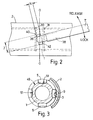
- the concave curvature of the roller surface in a plane containing the rolling axis is complementary to the concave curvature of the tapering surfaces as can be seen in Figure 3.
- the surface of each roller is in contact with the associated tapering surface across the whole of its axial width, thus providing a relatively large area of contact.
- each cage and the nearer end stop 14,15 Positioned respectively between each cage and the nearer end stop 14,15 so as to encircle the first member 1 coaxially are two helical springs 20,21, one spring 20 being positioned between one end stop 14 and one cage 23 and the other spring 21 being positioned between the other end stop 15 and the other cage 24.
- the springs 20,21 are arranged to be in compression so that a biassing force acts against the cages 23, 24 at all times to press the rollers therein against the associated tapering surface 3 or 4.
- the two sets of rollers 5,6 are wedged between the two tapering surfaces and the facing tracks on the surface of the first member 1 and prevent unwanted movement of the second member 2 longitudinally with respect to the first member.
- a release means is provided to enable the seat occupant to unlock the device and hence allow the position of the second member 2 to be adjusted relative to the first member 1 in a fore-and-aft direction.
- the release means comprises a pair of steel tubes 27,28 arranged coaxially on the first member 1.
- Each steel tube 27 or 28 is slidable simultaneously on the first member 1 outwards with respect to the plane of symmetry 0-0 so that their outer edges contact the two sets of rollers 5,6 and move them outwards against the biassing force applied by the two helical springs 20,21.
- an L-shaped rod 35 Positioned in a hole formed in the second member is an L-shaped rod 35 having a generally rectangular projection 36 formed on one end face of one of its two limbs and arranged to abut the first member 1.
- the projection has two diagonally opposed corners 40,42 each of which abuts a respective washer 30,31 which is positioned to surround the first member in contact with the inner end of the associated steel tube 27 or 28.
- the projection 36 has its two longer edges extending at right angles to the length of the handle 7. Their length J is greater than the width of the rod which forms part of the handle. The shorter edges have lengths N less than the rod width.
- the other limb 38 of the rod extends at right angles to the limb having the projection 36 and fits inside a tubular part of the handle 7 lying alongside the second member 2.
- the handle 7 lies parallel to the two members 1,2 in a generally horizontal position, the second member 2 being locked relative to the first member 1. Movement of the handle from a horizontal, locked position towards the vertical, released position rotates the rod 35 and in particular the projection 36.
- the two corners 40,42 contact the washers 30,31 to cause them to move apart i.e. away from the plane of symmetry 0-0.
- the washers are spaced apart by their maximum distance i.e. by the length J of the longer edges of the rectangular projection 36.
- This movement of the washers 30,31 causes the two tubes 27, 28 and the rollers 5,6 at the opposite end of the tubes to the washers to move against the spring biassing and out of contact with the tapering surfaces 3,4.
- the seat occupant may then reposition the seat carried on the second member 2 with respect to the first member 1 and once in the required new position, lock it in the new position by moving the handle 7 back to the horizontal position.
- This allows the two springs 20,21 to move the cages 23,24, the sets of rollers 5,6, the steel tubes 27,28 and the washers 30,31 towards the plane of symmetry 0-0. In this horizontal position of the handle the distance between the washers 30,31 is equal to the length N of the shorter edges of the rectangular projection 36.
- rollers particularly rollers each having a convex surface in a plane containing the rolling axis of the roller, and complementary surfaces in the tracks and on the rings 8,9 provides much greater areas of contact compared with spherical balls acting on a cylindrical surface as in the devices described in the aforementioned prior publications. As a result unwanted indentation does not occur, and wear is very much reduced. Further the locking forces are increased.
- two locking devices are provided, one for each side of the seat, linked together by a cable, rod, lever system or other mechanical linkage so that operation of the handle on one device operates the release mechanisms of both devices.
Landscapes
- Engineering & Computer Science (AREA)
- Mechanical Engineering (AREA)
- General Engineering & Computer Science (AREA)
- Aviation & Aerospace Engineering (AREA)
- Transportation (AREA)
- Seats For Vehicles (AREA)
Applications Claiming Priority (2)
| Application Number | Priority Date | Filing Date | Title |
|---|---|---|---|
| GB9326348 | 1993-12-23 | ||
| GB939326348A GB9326348D0 (en) | 1993-12-23 | 1993-12-23 | Locking device |
Publications (1)
| Publication Number | Publication Date |
|---|---|
| EP0663314A1 true EP0663314A1 (de) | 1995-07-19 |
Family
ID=10747134
Family Applications (1)
| Application Number | Title | Priority Date | Filing Date |
|---|---|---|---|
| EP94309129A Withdrawn EP0663314A1 (de) | 1993-12-23 | 1994-12-07 | Verriegelungsvorrichtung |
Country Status (3)
| Country | Link |
|---|---|
| EP (1) | EP0663314A1 (de) |
| JP (1) | JPH07205693A (de) |
| GB (2) | GB9326348D0 (de) |
Cited By (5)
| Publication number | Priority date | Publication date | Assignee | Title |
|---|---|---|---|---|
| US8166620B2 (en) | 2005-04-14 | 2012-05-01 | Balltec Limited | Connector |
| CN103062176A (zh) * | 2013-01-06 | 2013-04-24 | 陈庆元 | 一种摄影器材上的伸缩管防脱锁紧装置 |
| US9810364B2 (en) | 2015-11-20 | 2017-11-07 | Usa Industries, Inc. | Gripping apparatus and devices for plugging of pipes, orifices or connecting |
| WO2019162671A1 (en) * | 2018-02-20 | 2019-08-29 | F Klucznik & Son Limited | Locking mechanism |
| EP4331962A1 (de) * | 2022-08-29 | 2024-03-06 | Giant Manufacturing Co., Ltd. | Teleskopmechanismus |
Families Citing this family (3)
| Publication number | Priority date | Publication date | Assignee | Title |
|---|---|---|---|---|
| EP0770513B1 (de) * | 1995-10-05 | 2000-01-12 | Bertrand Faure Equipements S.A. | Unbegrenzt verstellbarer Gleitschienenverriegelungsmechanismus |
| JP5958199B2 (ja) * | 2012-09-03 | 2016-07-27 | トヨタ紡織株式会社 | スライド装置 |
| CN110131547A (zh) * | 2019-04-12 | 2019-08-16 | 东莞市中科冠腾科技股份有限公司 | 一种压铸件配合使用的开口衬套 |
Citations (6)
| Publication number | Priority date | Publication date | Assignee | Title |
|---|---|---|---|---|
| DE67806C (de) * | A. WAHL in München | Kugeigesperre mit Klemmkegeln | ||
| GB772203A (en) * | 1955-03-24 | 1957-04-10 | Arne Holmberg | Locking device |
| GB1067133A (en) * | 1963-03-14 | 1967-05-03 | Giulio Cavioni | A locking device |
| US3467352A (en) * | 1965-11-12 | 1969-09-16 | Wilhelm Valentin Bohler | Adjustable clamp |
| DE3508739A1 (de) * | 1985-03-12 | 1986-09-18 | Lennarz, Angela, 5138 Heinsberg | Schnellkupplung, insbesondere zur arretierung eines verteilers auf dem mast eines grossschirms |
| EP0540252A1 (de) * | 1991-10-29 | 1993-05-05 | Dunlop Cox Limited | Feststellvorrichtung |
-
1993
- 1993-12-23 GB GB939326348A patent/GB9326348D0/en active Pending
-
1994
- 1994-12-07 EP EP94309129A patent/EP0663314A1/de not_active Withdrawn
- 1994-12-07 GB GB9424715A patent/GB2285089B/en not_active Expired - Fee Related
- 1994-12-22 JP JP32019294A patent/JPH07205693A/ja active Pending
Patent Citations (6)
| Publication number | Priority date | Publication date | Assignee | Title |
|---|---|---|---|---|
| DE67806C (de) * | A. WAHL in München | Kugeigesperre mit Klemmkegeln | ||
| GB772203A (en) * | 1955-03-24 | 1957-04-10 | Arne Holmberg | Locking device |
| GB1067133A (en) * | 1963-03-14 | 1967-05-03 | Giulio Cavioni | A locking device |
| US3467352A (en) * | 1965-11-12 | 1969-09-16 | Wilhelm Valentin Bohler | Adjustable clamp |
| DE3508739A1 (de) * | 1985-03-12 | 1986-09-18 | Lennarz, Angela, 5138 Heinsberg | Schnellkupplung, insbesondere zur arretierung eines verteilers auf dem mast eines grossschirms |
| EP0540252A1 (de) * | 1991-10-29 | 1993-05-05 | Dunlop Cox Limited | Feststellvorrichtung |
Cited By (8)
| Publication number | Priority date | Publication date | Assignee | Title |
|---|---|---|---|---|
| US8166620B2 (en) | 2005-04-14 | 2012-05-01 | Balltec Limited | Connector |
| CN103062176A (zh) * | 2013-01-06 | 2013-04-24 | 陈庆元 | 一种摄影器材上的伸缩管防脱锁紧装置 |
| CN103062176B (zh) * | 2013-01-06 | 2016-08-03 | 陈庆元 | 一种摄影器材上的伸缩管防脱锁紧装置 |
| US9810364B2 (en) | 2015-11-20 | 2017-11-07 | Usa Industries, Inc. | Gripping apparatus and devices for plugging of pipes, orifices or connecting |
| US9927058B2 (en) | 2015-11-20 | 2018-03-27 | Usa Industries, Inc. | Gripping apparatus and devices for plugging of pipes, orifices or connecting |
| WO2019162671A1 (en) * | 2018-02-20 | 2019-08-29 | F Klucznik & Son Limited | Locking mechanism |
| EP4331962A1 (de) * | 2022-08-29 | 2024-03-06 | Giant Manufacturing Co., Ltd. | Teleskopmechanismus |
| US12377926B2 (en) | 2022-08-29 | 2025-08-05 | Giant Manufacturing Co., Ltd. | Telescopic mechanism |
Also Published As
| Publication number | Publication date |
|---|---|
| JPH07205693A (ja) | 1995-08-08 |
| GB9326348D0 (en) | 1994-02-23 |
| GB9424715D0 (en) | 1995-02-01 |
| GB2285089A (en) | 1995-06-28 |
| GB2285089B (en) | 1997-07-02 |
Similar Documents
| Publication | Publication Date | Title |
|---|---|---|
| EP0557865B1 (de) | Energiewandler in einem Rückhaltesystem für Fahrzeuginsassen | |
| DE4301403C2 (de) | Zentralverschluß für Mehrpunktsicherheitsgurte | |
| DE202007000115U1 (de) | Vorrichtung zum Verriegeln und Lösen einer Schraubspitze | |
| DE4415960A1 (de) | Transportsicherung bei einem Kettenspanner | |
| EP0806327B1 (de) | Linearantrieb für ein Fahrzeuginsassen-Rückhaltesystem | |
| JPS59207113A (ja) | 直線的に無段階変位が可能な機構 | |
| GB2285089A (en) | A locking device for a vehicle seat slide | |
| DE102016222795A1 (de) | Lenkwelle für ein Kraftfahrzeug | |
| DE20013256U1 (de) | Betätigungsvorrichtung für ein bewegliches Element | |
| EP0418507A1 (de) | Brems- oder/und Klemmeinrichtung | |
| EP0511500A1 (de) | Blockierbare Hubvorrichtung zum stufenlosen Verstellen von Stuhlsitzen | |
| DE69012699T2 (de) | Einrichtung zum Ausgleich des Spieles zwischen dem Satelliten und den Zähnen der Flansche der Untersetzungsgetriebe für die Verstellung der Sitzposition, insbesondere von Kraftfahrzeuge. | |
| EP0540252A1 (de) | Feststellvorrichtung | |
| DE19980346B4 (de) | Insbesondere Linear wirkendes Klemmgesperre | |
| EP0242859A2 (de) | Gleitschienenführung für Fahrzeugsitze | |
| EP0362239A1 (de) | Klemmvorrichtung für das gurtband von kraftfahrzeugsicherheitsgurten. | |
| US6527342B2 (en) | Cone recliner/clutch mechanism | |
| DE19642894A1 (de) | Uniaxial wirkendes Klemmkörpergesperre | |
| DE4140279C1 (de) | ||
| EP0386494B1 (de) | Vorrichtung zum Verhindern unbeabsichtigter Bewegungsabläufen bei mindestens einer um eine Achse kippbaren Fläche, wie Rückenlehne von Stühlen, Türklappe an Schränken u.a. | |
| US5709133A (en) | Linear locking device | |
| DE10134355A1 (de) | Verstellbeschlag für Kraftfahrzeugsitze | |
| DE2144507A1 (de) | Gelenklager | |
| US3539210A (en) | Pivot joint and ratchet means | |
| EP0618111A1 (de) | Gurtstraffer für ein Fahrzeugsicherheitsgurtsystem |
Legal Events
| Date | Code | Title | Description |
|---|---|---|---|
| PUAI | Public reference made under article 153(3) epc to a published international application that has entered the european phase |
Free format text: ORIGINAL CODE: 0009012 |
|
| AK | Designated contracting states |
Kind code of ref document: A1 Designated state(s): DE DK ES FR GB IT SE |
|
| STAA | Information on the status of an ep patent application or granted ep patent |
Free format text: STATUS: THE APPLICATION IS DEEMED TO BE WITHDRAWN |
|
| 18D | Application deemed to be withdrawn |
Effective date: 19960120 |