EP0663568B1 - Four de cuisson domestique - Google Patents
Four de cuisson domestique Download PDFInfo
- Publication number
- EP0663568B1 EP0663568B1 EP95400055A EP95400055A EP0663568B1 EP 0663568 B1 EP0663568 B1 EP 0663568B1 EP 95400055 A EP95400055 A EP 95400055A EP 95400055 A EP95400055 A EP 95400055A EP 0663568 B1 EP0663568 B1 EP 0663568B1
- Authority
- EP
- European Patent Office
- Prior art keywords
- muffle
- sensor
- fumes
- temperature
- oven
- Prior art date
- Legal status (The legal status is an assumption and is not a legal conclusion. Google has not performed a legal analysis and makes no representation as to the accuracy of the status listed.)
- Revoked
Links
- 238000010411 cooking Methods 0.000 title claims abstract description 22
- 239000003517 fume Substances 0.000 claims abstract description 35
- 235000013305 food Nutrition 0.000 claims abstract description 13
- 239000000203 mixture Substances 0.000 claims abstract description 4
- 239000007789 gas Substances 0.000 claims description 23
- 238000006555 catalytic reaction Methods 0.000 claims description 7
- 238000004140 cleaning Methods 0.000 claims description 6
- 230000006872 improvement Effects 0.000 claims description 6
- 239000012080 ambient air Substances 0.000 claims description 4
- 231100000252 nontoxic Toxicity 0.000 claims description 2
- 230000003000 nontoxic effect Effects 0.000 claims description 2
- 239000002341 toxic gas Substances 0.000 claims description 2
- 238000007599 discharging Methods 0.000 claims 1
- 238000012544 monitoring process Methods 0.000 claims 1
- 239000003054 catalyst Substances 0.000 abstract description 6
- 230000003197 catalytic effect Effects 0.000 abstract description 3
- 239000000463 material Substances 0.000 abstract 1
- 238000000197 pyrolysis Methods 0.000 description 9
- 239000003570 air Substances 0.000 description 6
- 238000004891 communication Methods 0.000 description 6
- 238000010438 heat treatment Methods 0.000 description 5
- CURLTUGMZLYLDI-UHFFFAOYSA-N Carbon dioxide Chemical compound O=C=O CURLTUGMZLYLDI-UHFFFAOYSA-N 0.000 description 4
- KDLHZDBZIXYQEI-UHFFFAOYSA-N Palladium Chemical compound [Pd] KDLHZDBZIXYQEI-UHFFFAOYSA-N 0.000 description 4
- 230000003647 oxidation Effects 0.000 description 4
- 238000007254 oxidation reaction Methods 0.000 description 4
- BASFCYQUMIYNBI-UHFFFAOYSA-N platinum Chemical compound [Pt] BASFCYQUMIYNBI-UHFFFAOYSA-N 0.000 description 4
- UGFAIRIUMAVXCW-UHFFFAOYSA-N Carbon monoxide Chemical compound [O+]#[C-] UGFAIRIUMAVXCW-UHFFFAOYSA-N 0.000 description 3
- 238000004458 analytical method Methods 0.000 description 3
- 229910002091 carbon monoxide Inorganic materials 0.000 description 3
- 150000001875 compounds Chemical class 0.000 description 3
- 239000003925 fat Substances 0.000 description 3
- 229930195733 hydrocarbon Natural products 0.000 description 3
- 238000000034 method Methods 0.000 description 3
- 230000009466 transformation Effects 0.000 description 3
- 238000004566 IR spectroscopy Methods 0.000 description 2
- 229910002092 carbon dioxide Inorganic materials 0.000 description 2
- 239000001569 carbon dioxide Substances 0.000 description 2
- 229910010293 ceramic material Inorganic materials 0.000 description 2
- 238000010586 diagram Methods 0.000 description 2
- 230000000694 effects Effects 0.000 description 2
- 150000002430 hydrocarbons Chemical class 0.000 description 2
- 229910052763 palladium Inorganic materials 0.000 description 2
- 239000008188 pellet Substances 0.000 description 2
- 229910052697 platinum Inorganic materials 0.000 description 2
- 239000010970 precious metal Substances 0.000 description 2
- 238000011084 recovery Methods 0.000 description 2
- 230000004044 response Effects 0.000 description 2
- 229910052703 rhodium Inorganic materials 0.000 description 2
- 239000010948 rhodium Substances 0.000 description 2
- MHOVAHRLVXNVSD-UHFFFAOYSA-N rhodium atom Chemical compound [Rh] MHOVAHRLVXNVSD-UHFFFAOYSA-N 0.000 description 2
- 239000000779 smoke Substances 0.000 description 2
- OKTJSMMVPCPJKN-UHFFFAOYSA-N Carbon Chemical compound [C] OKTJSMMVPCPJKN-UHFFFAOYSA-N 0.000 description 1
- 239000004215 Carbon black (E152) Substances 0.000 description 1
- 238000005033 Fourier transform infrared spectroscopy Methods 0.000 description 1
- UFHFLCQGNIYNRP-UHFFFAOYSA-N Hydrogen Chemical compound [H][H] UFHFLCQGNIYNRP-UHFFFAOYSA-N 0.000 description 1
- 238000010521 absorption reaction Methods 0.000 description 1
- 238000009529 body temperature measurement Methods 0.000 description 1
- 229910052799 carbon Inorganic materials 0.000 description 1
- 238000006243 chemical reaction Methods 0.000 description 1
- 238000002485 combustion reaction Methods 0.000 description 1
- -1 compounds hydrocarbons Chemical class 0.000 description 1
- 238000010276 construction Methods 0.000 description 1
- 238000005336 cracking Methods 0.000 description 1
- 238000013211 curve analysis Methods 0.000 description 1
- 230000006378 damage Effects 0.000 description 1
- 239000004519 grease Substances 0.000 description 1
- 229910052739 hydrogen Inorganic materials 0.000 description 1
- 239000001257 hydrogen Substances 0.000 description 1
- 239000011810 insulating material Substances 0.000 description 1
- 230000004048 modification Effects 0.000 description 1
- 238000012986 modification Methods 0.000 description 1
- 230000008569 process Effects 0.000 description 1
- 238000010926 purge Methods 0.000 description 1
- 230000005855 radiation Effects 0.000 description 1
- 231100000331 toxic Toxicity 0.000 description 1
- 230000002588 toxic effect Effects 0.000 description 1
- 238000012549 training Methods 0.000 description 1
Images


Classifications
-
- F—MECHANICAL ENGINEERING; LIGHTING; HEATING; WEAPONS; BLASTING
- F24—HEATING; RANGES; VENTILATING
- F24C—DOMESTIC STOVES OR RANGES ; DETAILS OF DOMESTIC STOVES OR RANGES, OF GENERAL APPLICATION
- F24C15/00—Details
- F24C15/20—Removing cooking fumes
- F24C15/2007—Removing cooking fumes from oven cavities
- F24C15/2014—Removing cooking fumes from oven cavities with means for oxidation of cooking fumes
-
- F—MECHANICAL ENGINEERING; LIGHTING; HEATING; WEAPONS; BLASTING
- F24—HEATING; RANGES; VENTILATING
- F24C—DOMESTIC STOVES OR RANGES ; DETAILS OF DOMESTIC STOVES OR RANGES, OF GENERAL APPLICATION
- F24C14/00—Stoves or ranges having self-cleaning provisions, e.g. continuous catalytic cleaning or electrostatic cleaning
- F24C14/02—Stoves or ranges having self-cleaning provisions, e.g. continuous catalytic cleaning or electrostatic cleaning pyrolytic type
Definitions
- the present invention relates to an improvement to domestic cooking ovens or cookers, in which one carries out the destruction or at least the transformation of vapors or fumes created inside oven muffle when cooking food, especially performing efficient oxidation of volatile compounds dangerous, especially carbon monoxide or products hydrocarbons, present in these vapors or fumes, by means of a catalytic action of the latter.
- the catalyst used usually consists of a block or pellet of ceramic material, covered or impregnated with one or more precious metals, of the kind platinum, palladium, rhodium or others, which known, allow the transformation of carbon monoxide into carbon dioxide at lower temperature, especially at that where the fumes or vapors come out of the muffle to enter the free recovery space located outside of it, with or without additional means to raise this temperature at the value necessary for complete realization of the corresponding reaction.
- This catalyst is generally in the form of a block or a cylindrical tablet, drilled with holes for the passage of gases or fumes, this block being mounted in a chimney-shaped duct that connects the inside of the muffle in the space where these gases and fumes collect. Products combustion thus oxidized, after collecting in this space at the exit of the conduit, can then be trained outwards into the atmosphere surrounding the oven, thanks to entrained air from the fan, harmless for users (See EP-0 500 471).
- the effectiveness of the catalysis block depends primarily on its degree of saturation and the temperature at which it is brought into operation.
- means are provided which make it possible to measure in gas temperature at the block level and also to control the nature of these gases in order to be able to act on the instantaneous value or the growth of the temperature created by the electrical resistances which cook the food or other residues present in the muffle, avoiding this saturation.
- temperature measurement and control of the nature of the gases are produced by means of appropriate sensors, arranged in the connecting pipe before or immediately after the catalysis block, allowing the ensuing difference between the temperature in the muffle and that at the block level, by comparison with a reference value to control the rate of temperature rise during cooking or pyrolysis.
- the temperature can reach 250 ° C, which already exceeds capacities of the usual sensors to support it.
- the temperature can reach in the duct 400 to 450 ° connection, where no usual sensor presenting an acceptable cost to be fitted in a baking oven domestic can not agree.
- the present invention relates to an improvement made for baking ovens or the like, heated by electrical resistors, in which the measuring sensors implemented are localized differently from solutions known in the state of the art, allowing in particular their use whatever the temperature in the oven, even in the pyrolysis phase.
- the senor is fixed to one or other of the two sheets delimiting the collector.
- the senor is located beyond and downstream of the conduit which crosses the collector in the direction gas flow, and opens into an open hood where these gases are taken up by the fan which then expels them into the manifold from the outside of the conduit.
- reference 1 designates the furnace considered taken as a whole, this oven comprising in particular and in itself classic way in this kind of device, a external enclosure 2 and, mounted inside thereof, a muffle 3, inside which the food, in particular by means of electrical resistors heating (not shown), arranged for example in the sides of the muffle, usually between it and the wall internal of enclosure 2 or any other suitable location.
- the oven can be conventional heating or more elaborate, especially of the kind known as fan heat.
- the oven may include, in addition to the heating means above, a source of high-level electrical radiation frequency, for microwave heating.
- the muffle 3 is closed in use of the oven by a door front 4, articulated in the corresponding face of the enclosure, this door being able to comprise a porthole 5 allowing to see inside the muffle the cooking of foods introduced into the internal region 6 delimited in this mitt.
- the fumes or vapors produced during this cooking are extracted from the muffle through a discharge pipe 7, connecting the internal region 6 of the muffle with a manifold 8, formed between two sheets substantially parallel, respectively 9 and 10, leaving between them a free space 11 or into which the end of the conduit 7 opposite to that which ensures communication with inside the muffle.
- the space 11 is itself joined by a connecting tube 12 with a fan 13, usually called a tangential, housed inside enclosure 2 behind and above the muffle 3, this fan ensuring the supply of a flow rate air suitable for entraining fumes and vapors collected in space 11 by the conduit 7 before they are discharge outside the enclosure through an outlet 14 provided in the front side thereof, above the door 4, this orifice may include a grid of protection (not shown).
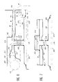
- FIGS 2 and 3 illustrate in more detail the particular realization of the upper part of the muffle 3 and of the connecting duct 7 between this muffle and the free space 11 formed in the collector 8.
- door 4 closing the muffle at the front of it has a system closure 15, cooperating with a locking member 16, allowing in particular to keep the door closed and in particular to avoid any untimely opening of this last in pyrolysis phase for cleaning the oven.
- the muffle 3 has an upper plate 17 forming a ceiling and, attached and immobilized thereon a second sheet 18, welded in 19 on the first and delimiting therewith a flat box 20, thus provided in the ceiling of the muffle.
- a strong electrical resistance 21 called grill resistance and intended for the surface cooking of food to the inside of the mitt, when it is brought to a red temperature of the order of 7 to 800 ° C. Note that this resistance is also used and if necessary to pyrolise the oven when brought to this temperature, in in this case realizing a cracking of the fat molecules and other hydrocarbon products that have soiled the walls of the oven, this combined use of resistor 21 being already well known in the art.
- Resistor 21 is generally formed of an element continuous with successive convolutions so to be distributed as well as possible over the entire surface of the ceiling of the muffle, in particular on the right of the flat box 20. It thus comprises longitudinal parts 22 extending in the muffle between the bottom of it and the vicinity of the front door 4, these longitudinal parts being connected from one to the other at their ends by parts of link 23 curves or straight lines, resistance being connected by connection members 24 to a source of Electric power.
- conduit 7 The free space 11 arranged between sheets 9 and 10 of the collector 8 and the internal region of the box 20 communicate by conduit 7.
- This is constituted by means of a tube element 24, partially opening into the muffle lower and in sheet 10 in the upper part through flanges of the same diameter, 25 and 26, crossing in particular an appropriate layer 27 of an insulating material placed between the collector and the box.
- a catalysis block 28 preferably in the form of a pellet a suitable ceramic material, covered or impregnated of a precious metal of the usual kind for such use, in particular of platinum, palladium, rhodium or others, in particular allow a efficient oxidation of certain volatile smoke compounds or vapors created in the flask and escaping therefrom through the box 20 in which they are collected after passage through block 28 which is at this effect provided with a set of communication passages 29.
- Control of the temperature in the muffle by command electrical resistances thereof, particularly during cooking food and if necessary to achieve the cleaning operation by pyrolysis, is ensured, so in itself known by at least one sensor sensitive to the temperature or composition of vapors or fumes produced in the oven and preferably near the exhaust duct 7 containing the catalysis block, in one place that gives the best picture of the state of cooking before the fumes and vapors analyzed are diluted by the ambient air supplied by the fan which drives them outside the oven enclosure.
- the oven always uses a sensor 30 of the aforementioned kind but arranged in a place such that it does supports a relatively low temperature, at most equal to 250 °, even when the temperature in the muffle reaches or exceeds 450 °, in particular in the phase of pyrolysis.
- the senor 30 is thus disposed in the manifold 8, substantially in downstream of the communication conduit 7, while being fixed on the upper sheet 9 of this connector.
- the place chosen is such the sensor is actually placed in a lower temperature environment but in which it is still essentially surrounded by gases and fumes delivered by the communication conduit inside the collector, without these gases and fumes having yet been greatly diluted by the air discharged by the fan 13.
- the senor 30 shown is illustrated with its electrical connections 31, making it possible to connect it to a measuring device integrated in the oven enclosure, this device itself connected to a display opposite front of this oven, allowing to know at any time the actual measured temperature.
- the increase in concentration of a predetermined gas corresponds to a modification of the signal from this sensor.
- a predetermined gas at which is more specially sensitive the sensor, for example oxide carbon or hydrogen in combined form
- we can therefore to a certain extent control the cooking of food inside the oven the example illustrated on the Figure 8 showing on the curve Analysis of a given gas in infrared spectrometry and curve B the response provided by the sensor, substantially homologous but offset compared to the first, the increase in slope of the curve being characteristic of the cooking state produced in depending on the product in the oven.
- Figures 4 and 5 on which we repeated the same reference figures, illustrate a variant of embodiment in which the sensor 30 is no longer fixed on the upper sheet 9 of the manifold 8 but on the sheet lower 10, the choice can be dictated by constraint of fitting out the collector and connecting the sensor to its measuring device.
- the sensor 30 is arranged on the upper sheet 9 of the collector 8 but outside of the latter.
- the exhaust duct 7 delivers the gases and fumes from the muffle cavity 6 in a space provided under a cover 32, comprising a horizontal flat return 33 returning these gases or fumes to the passages suction fan 13 which then pushes them back into the manifold 8 from the outside of the part of the duct 7 which crosses it.
- the senor is placed in an area where the gases which sweep it are at a temperature appreciably lower than that prevailing in the conduit of communication, before and even after passing through the block of catalysis. Under these conditions, it becomes possible to use sensors presenting a cost price acceptable and also to implement these on pyrolysis ovens where this use is until now prevented due to temperatures encountered.
- the electrical connections of the sensor may be more simple and also less expensive since the links can also be done outside the areas high temperature.
Landscapes
- Engineering & Computer Science (AREA)
- Chemical & Material Sciences (AREA)
- Combustion & Propulsion (AREA)
- Mechanical Engineering (AREA)
- General Engineering & Computer Science (AREA)
- Chemical Kinetics & Catalysis (AREA)
- Jellies, Jams, And Syrups (AREA)
- Electric Stoves And Ranges (AREA)
- Baking, Grill, Roasting (AREA)
Description
- La Figure 1 est une vue schématique en perspective d'un four de cuisson domestique mettant en oeuvre les dispositions de l'invention.
- Les Figures 2 et 3 sont des vues respectivement en coupe longitudinale partielle et en coupe transversale, à plus grande échelle, de la partie supérieure du moufle du four de la Figure 1, passant par l'axe du conduit d'évacuation des vapeurs et fumées et selon des plans respectivement perpendiculaire et parallèle à la porte située à l'avant du four pour fermer le moufle.
- Les Figures 4 et 5 sont des vues analogues aux Figures 2 et 3 d'une seconde variante de réalisation.
- Les Figures 6 et 7 sont des vues analogues d'une troisième variante de réalisation.
- La Figure 8 est un diagramme illustrant schématiquement la courbe de réponse d'un capteur monté conformément à l'invention et de la courbe donnée par l'analyse en infrarouge à transformée de Fourier des vapeurs ou fumées à l'intérieur du moufle.
Claims (3)
- Perfectionnement aux fours de cuisson domestiques, comportant un moufle (3) de réception des aliments à cuire, une enceinte externe (2) entourant le moufle (3) avec une porte pivotante (4) d'accès à celui-ci, un collecteur (8) logé entre le moufle (3) et l'enceinte (2), formé de deux tôles (9, 10) sensiblement parallèles délimitant un espace (11) où se recueillent les vapeurs ou fumées créées dans le moufle (3), communiquant avec celui-ci par un conduit (7) dans lequel est de préférence monté un bloc de catalyse (28) traversé par ces vapeurs ou fumées provenant du moufle (3) pour leur transformation en gaz non toxiques se rassemblant dans le collecteur (8) avant d'être évacués hors de l'enceinte (2) par des orifices de sortie (14) ménagés dans celle-ci, caractérisé en ce que le contrôle de la température dans le moufle (3), en phase de cuisson ou de nettoyage par pyrolyse, est réalisé au moyen d'au moins un capteur (30) sensible à la température ou à la composition des vapeurs ou fumées, pour fournir un signal de commande des résistances électriques (21) du four agissant sur cette température, et en ce que le capteur (30) est disposé au-delà mais sensiblement au voisinage d'un orifice par lequel le conduit (7) est en communication avec l'espace (11) recueillant les gaz provenant du moufle (3) et balayé en permanence par de l'air ambiant fourni par un ventilateur (13) débitant à l'intérieur du collecteur (8), de manière à réduire la température de ces gaz au contact du capteur (30).
- Perfectionnement selon la revendication 1, caractérisé en ce que le capteur (30) est fixé sur l'une ou l'autre des deux tôles (9, 10) délimitant le collecteur (8).
- Perfectionnement selon l'une des revendications 1 ou 2, caractérisé en ce que le capteur (30) est situé au-delà et en aval du conduit (7) qui traverse le collecteur (8) dans le sens d'écoulement des gaz, et débouche dans un capot ouvert (32) où ces gaz sont repris par le ventilateur (13) qui les refoule ensuite dans le collecteur par l'extérieur du conduit.
Applications Claiming Priority (2)
| Application Number | Priority Date | Filing Date | Title |
|---|---|---|---|
| FR9400281 | 1994-01-12 | ||
| FR9400281A FR2714959A1 (fr) | 1994-01-12 | 1994-01-12 | Four de cuisson domestique. |
Publications (2)
| Publication Number | Publication Date |
|---|---|
| EP0663568A1 EP0663568A1 (fr) | 1995-07-19 |
| EP0663568B1 true EP0663568B1 (fr) | 1998-04-08 |
Family
ID=9458967
Family Applications (1)
| Application Number | Title | Priority Date | Filing Date |
|---|---|---|---|
| EP95400055A Revoked EP0663568B1 (fr) | 1994-01-12 | 1995-01-11 | Four de cuisson domestique |
Country Status (4)
| Country | Link |
|---|---|
| EP (1) | EP0663568B1 (fr) |
| AT (1) | ATE164933T1 (fr) |
| DE (1) | DE69501965T2 (fr) |
| FR (1) | FR2714959A1 (fr) |
Cited By (2)
| Publication number | Priority date | Publication date | Assignee | Title |
|---|---|---|---|---|
| DE10202132A1 (de) * | 2002-01-21 | 2003-07-31 | Bsh Bosch Siemens Hausgeraete | Backofen mit einem Wrasenkanal |
| EP4686875A1 (fr) * | 2024-07-30 | 2026-02-04 | Electrolux Appliances Aktiebolag | Appareil de cuisson |
Families Citing this family (11)
| Publication number | Priority date | Publication date | Assignee | Title |
|---|---|---|---|---|
| EP0858278B8 (fr) * | 1996-07-29 | 2002-11-13 | Koninklijke Philips Electronics N.V. | Dispositif de friture |
| DE19920345C1 (de) * | 1999-05-04 | 2000-12-21 | Aeg Hausgeraete Gmbh | Garofen mit Wrasenabführung und Frischluftbeimischung |
| DE10163183A1 (de) * | 2001-12-21 | 2003-07-03 | Bsh Bosch Siemens Hausgeraete | Gargerätemuffel sowie Verfahren zur Herstellung einer Gargerätemuffel |
| EP1400758A1 (fr) * | 2002-09-23 | 2004-03-24 | CANDY S.p.A. | Element de chauffage pour un four cuisinière |
| DE102004056839A1 (de) * | 2004-11-25 | 2006-06-01 | Miele & Cie. Kg | Backofen mit einem Wrasenkanal, in dem ein Katalysator und ein Gassensor angeordnet sind |
| FR2899968B1 (fr) * | 2006-04-12 | 2008-07-18 | Brandt Ind Sas | Dispositif de mesure de temperature dans un four de cuisson et four de cuisson comprenant un tel dispositif de mesure de temperature |
| DE102006047587A1 (de) | 2006-10-05 | 2008-04-10 | Miele & Cie. Kg | Backofen mit einer Backmuffel und einem Querstromlüfter |
| KR101203444B1 (ko) * | 2012-06-12 | 2012-11-22 | 이영희 | 오염물질 열분해 장치가 부착된 오븐 |
| DE102013107361A1 (de) * | 2013-07-11 | 2015-01-15 | Miele & Cie. Kg | Gargerät und Katalysatoreinrichtung |
| WO2018024566A1 (fr) | 2016-08-03 | 2018-02-08 | Arcelik Anonim Sirketi | Four à extraction de fumées améliorée |
| EP3412973B1 (fr) * | 2017-06-07 | 2024-02-28 | Electrolux Appliances Aktiebolag | Four comprenant un ensemble de détection des paramètres de fonctionnement à l'intérieur de la cavité du four |
Family Cites Families (6)
| Publication number | Priority date | Publication date | Assignee | Title |
|---|---|---|---|---|
| AT324508B (de) * | 1973-02-02 | 1975-09-10 | Burger Eisenwerke Ag | Verfahren und einrichtung zum selbsttätigen reinigen der innenwände eines brat- oder backofens |
| DE3209541A1 (de) * | 1982-03-16 | 1983-09-29 | Bosch-Siemens Hausgeräte GmbH, 7000 Stuttgart | Backofen |
| US4601279A (en) * | 1984-07-10 | 1986-07-22 | Societe De Dietrich | Pyrolytic self-cleaning domestic oven with improved means for protecting electronic panel and controls from heat damages |
| DE3703539A1 (de) * | 1987-02-06 | 1988-08-18 | Buderus Kuechentechnik | Vorrichtung zur steuerung der dampfleistung eines mit dampf betriebenen gargeraetes |
| FR2673268A1 (fr) * | 1991-02-21 | 1992-08-28 | Scholtes Ets Eugen | Four de cuisson electrique a usage domestique. |
| FR2673267A1 (fr) * | 1991-02-21 | 1992-08-28 | Scholtes Ets Eugen | Four de cuisson domestique. |
-
1994
- 1994-01-12 FR FR9400281A patent/FR2714959A1/fr active Pending
-
1995
- 1995-01-11 DE DE69501965T patent/DE69501965T2/de not_active Revoked
- 1995-01-11 EP EP95400055A patent/EP0663568B1/fr not_active Revoked
- 1995-01-11 AT AT95400055T patent/ATE164933T1/de not_active IP Right Cessation
Cited By (5)
| Publication number | Priority date | Publication date | Assignee | Title |
|---|---|---|---|---|
| DE10202132A1 (de) * | 2002-01-21 | 2003-07-31 | Bsh Bosch Siemens Hausgeraete | Backofen mit einem Wrasenkanal |
| DE10202132B4 (de) * | 2002-01-21 | 2011-07-14 | BSH Bosch und Siemens Hausgeräte GmbH, 81739 | Backofen mit einem Wrasenkanal |
| EP4686875A1 (fr) * | 2024-07-30 | 2026-02-04 | Electrolux Appliances Aktiebolag | Appareil de cuisson |
| WO2026027139A1 (fr) * | 2024-07-30 | 2026-02-05 | Electrolux Appliances Aktiebolag | Appareil de cuisson comprenant un ensemble capteur à variables multiples |
| WO2026027374A1 (fr) * | 2024-07-30 | 2026-02-05 | Electrolux Appliances Aktiebolag | Procédé de supervision d'un processus de préparation thermique d'aliments et appareil de cuisson mettant en oeuvre ledit procédé |
Also Published As
| Publication number | Publication date |
|---|---|
| DE69501965D1 (de) | 1998-05-14 |
| DE69501965T2 (de) | 1998-08-13 |
| FR2714959A1 (fr) | 1995-07-13 |
| ATE164933T1 (de) | 1998-04-15 |
| EP0663568A1 (fr) | 1995-07-19 |
Similar Documents
| Publication | Publication Date | Title |
|---|---|---|
| EP0663568B1 (fr) | Four de cuisson domestique | |
| FR2816189A1 (fr) | Cuiseur a vapeur atmospherique muni d'un event perfectionne | |
| FR2545586A1 (fr) | Four electrique auto-nettoyant perfectionne | |
| FR2673268A1 (fr) | Four de cuisson electrique a usage domestique. | |
| FR2726633A1 (fr) | Procede de refroidissement de la porte d'un appareil de cuisson et appareil de cuisson mettant en oeuvre le procede | |
| EP2436289B1 (fr) | Appareil de cuisson électrique comportant un couvercle pivotant équipé d'un dispositif de récuperation des condensats | |
| FR2550611A1 (fr) | Foyer pour cheminee mixte destine a fonctionner ouvert et ferme | |
| FR2705766A1 (fr) | Dispositif pour l'oxydation catalytique des gaz et fumées, produits dans un four de cuisson domestique. | |
| EP0500471A1 (fr) | Four de cuisson domestique | |
| FR2681127A1 (fr) | Dispositif de refroidissement de la porte d'un appareil de cuisson. | |
| FR2661236A1 (fr) | Four de cuisson par contact direct a feu de bois, notamment encastrable dans un meuble de cuisine. | |
| EP1420673A1 (fr) | Appareil de cuisson d'aliments, notamment friteuse, comportant un catalyseur et des moyens de regulation dudit catalyseur | |
| FR2562213A1 (fr) | Appareil de cuisson combine gril-four a foyer unique | |
| EP0719987B1 (fr) | Cuisinière à gaz perfectionnée | |
| FR2748796A1 (fr) | Dispositif de refroidissement d'un ensemble de cuisson domestique | |
| FR2698431A1 (fr) | Montage d'un détecteur de gaz dans un four de cuisson. | |
| EP0146473B1 (fr) | Hublot pour appareil ménager de cuisson avec dispositif anti-buée | |
| FR2727300A1 (fr) | Appareil de cuisson electrique | |
| FR3044517A1 (fr) | Four a enceinte de cuisson modifiable | |
| EP0539299B1 (fr) | Appareil de cuisson mixte par rayonnement et vapeur | |
| EP2644031B1 (fr) | Procédé de préparation de baguette pour machine a pain | |
| EP0511052A1 (fr) | Enceinte de cuisson | |
| CA2890652C (fr) | Systeme de ventilation avec conduit d'evacuation ordinaire pour une cuisine commerciale | |
| EP1298394A1 (fr) | Four ménager | |
| EP1779039A1 (fr) | Procede et dispositif d"allumage par micro-ondes pour appareils de cuisson utilisant un combustible solide |
Legal Events
| Date | Code | Title | Description |
|---|---|---|---|
| PUAI | Public reference made under article 153(3) epc to a published international application that has entered the european phase |
Free format text: ORIGINAL CODE: 0009012 |
|
| AK | Designated contracting states |
Kind code of ref document: A1 Designated state(s): AT BE CH DE DK ES FR GB GR IE IT LI LU MC NL PT SE |
|
| RAX | Requested extension states of the european patent have changed |
Free format text: SI PAYMENT 950114 |
|
| 17P | Request for examination filed |
Effective date: 19951219 |
|
| RAP1 | Party data changed (applicant data changed or rights of an application transferred) |
Owner name: MERLONI ELECTROMENAGER |
|
| 17Q | First examination report despatched |
Effective date: 19970129 |
|
| GRAG | Despatch of communication of intention to grant |
Free format text: ORIGINAL CODE: EPIDOS AGRA |
|
| GRAG | Despatch of communication of intention to grant |
Free format text: ORIGINAL CODE: EPIDOS AGRA |
|
| GRAG | Despatch of communication of intention to grant |
Free format text: ORIGINAL CODE: EPIDOS AGRA |
|
| GRAH | Despatch of communication of intention to grant a patent |
Free format text: ORIGINAL CODE: EPIDOS IGRA |
|
| GRAH | Despatch of communication of intention to grant a patent |
Free format text: ORIGINAL CODE: EPIDOS IGRA |
|
| GRAA | (expected) grant |
Free format text: ORIGINAL CODE: 0009210 |
|
| ITF | It: translation for a ep patent filed | ||
| AK | Designated contracting states |
Kind code of ref document: B1 Designated state(s): AT BE CH DE DK ES FR GB GR IE IT LI LU MC NL PT SE |
|
| AX | Request for extension of the european patent |
Free format text: SI PAYMENT 950114 |
|
| PG25 | Lapsed in a contracting state [announced via postgrant information from national office to epo] |
Ref country code: NL Free format text: LAPSE BECAUSE OF FAILURE TO SUBMIT A TRANSLATION OF THE DESCRIPTION OR TO PAY THE FEE WITHIN THE PRESCRIBED TIME-LIMIT Effective date: 19980408 Ref country code: GR Free format text: LAPSE BECAUSE OF NON-PAYMENT OF DUE FEES Effective date: 19980408 Ref country code: AT Free format text: LAPSE BECAUSE OF FAILURE TO SUBMIT A TRANSLATION OF THE DESCRIPTION OR TO PAY THE FEE WITHIN THE PRESCRIBED TIME-LIMIT Effective date: 19980408 |
|
| REF | Corresponds to: |
Ref document number: 164933 Country of ref document: AT Date of ref document: 19980415 Kind code of ref document: T |
|
| REG | Reference to a national code |
Ref country code: CH Ref legal event code: EP |
|
| GBT | Gb: translation of ep patent filed (gb section 77(6)(a)/1977) |
Effective date: 19980409 |
|
| REF | Corresponds to: |
Ref document number: 69501965 Country of ref document: DE Date of ref document: 19980514 |
|
| PG25 | Lapsed in a contracting state [announced via postgrant information from national office to epo] |
Ref country code: SE Free format text: LAPSE BECAUSE OF FAILURE TO SUBMIT A TRANSLATION OF THE DESCRIPTION OR TO PAY THE FEE WITHIN THE PRESCRIBED TIME-LIMIT Effective date: 19980708 Ref country code: PT Free format text: LAPSE BECAUSE OF FAILURE TO SUBMIT A TRANSLATION OF THE DESCRIPTION OR TO PAY THE FEE WITHIN THE PRESCRIBED TIME-LIMIT Effective date: 19980708 Ref country code: DK Free format text: LAPSE BECAUSE OF FAILURE TO SUBMIT A TRANSLATION OF THE DESCRIPTION OR TO PAY THE FEE WITHIN THE PRESCRIBED TIME-LIMIT Effective date: 19980708 |
|
| PG25 | Lapsed in a contracting state [announced via postgrant information from national office to epo] |
Ref country code: ES Free format text: LAPSE BECAUSE OF FAILURE TO SUBMIT A TRANSLATION OF THE DESCRIPTION OR TO PAY THE FEE WITHIN THE PRESCRIBED TIME-LIMIT Effective date: 19980709 |
|
| REG | Reference to a national code |
Ref country code: IE Ref legal event code: FG4D Free format text: 79722 |
|
| NLV1 | Nl: lapsed or annulled due to failure to fulfill the requirements of art. 29p and 29m of the patents act | ||
| PG25 | Lapsed in a contracting state [announced via postgrant information from national office to epo] |
Ref country code: IE Free format text: LAPSE BECAUSE OF NON-PAYMENT OF DUE FEES Effective date: 19981023 |
|
| REG | Reference to a national code |
Ref country code: IE Ref legal event code: FD4D Ref document number: 79722 Country of ref document: IE |
|
| PLBI | Opposition filed |
Free format text: ORIGINAL CODE: 0009260 |
|
| PLBF | Reply of patent proprietor to notice(s) of opposition |
Free format text: ORIGINAL CODE: EPIDOS OBSO |
|
| 26 | Opposition filed |
Opponent name: BSH BOSCH UND SIEMENS HAUSGERAETE GMBH Effective date: 19981218 |
|
| PLBF | Reply of patent proprietor to notice(s) of opposition |
Free format text: ORIGINAL CODE: EPIDOS OBSO |
|
| PG25 | Lapsed in a contracting state [announced via postgrant information from national office to epo] |
Ref country code: MC Free format text: LAPSE BECAUSE OF NON-PAYMENT OF DUE FEES Effective date: 19990731 |
|
| PLBO | Opposition rejected |
Free format text: ORIGINAL CODE: EPIDOS REJO |
|
| APAC | Appeal dossier modified |
Free format text: ORIGINAL CODE: EPIDOS NOAPO |
|
| APAE | Appeal reference modified |
Free format text: ORIGINAL CODE: EPIDOS REFNO |
|
| APAC | Appeal dossier modified |
Free format text: ORIGINAL CODE: EPIDOS NOAPO |
|
| PGFP | Annual fee paid to national office [announced via postgrant information from national office to epo] |
Ref country code: FR Payment date: 20001219 Year of fee payment: 7 |
|
| PGFP | Annual fee paid to national office [announced via postgrant information from national office to epo] |
Ref country code: GB Payment date: 20001229 Year of fee payment: 7 |
|
| PGFP | Annual fee paid to national office [announced via postgrant information from national office to epo] |
Ref country code: CH Payment date: 20010115 Year of fee payment: 7 |
|
| PGFP | Annual fee paid to national office [announced via postgrant information from national office to epo] |
Ref country code: DE Payment date: 20010124 Year of fee payment: 7 |
|
| PGFP | Annual fee paid to national office [announced via postgrant information from national office to epo] |
Ref country code: LU Payment date: 20010129 Year of fee payment: 7 |
|
| PGFP | Annual fee paid to national office [announced via postgrant information from national office to epo] |
Ref country code: BE Payment date: 20010213 Year of fee payment: 7 |
|
| APAC | Appeal dossier modified |
Free format text: ORIGINAL CODE: EPIDOS NOAPO |
|
| RDAH | Patent revoked |
Free format text: ORIGINAL CODE: EPIDOS REVO |
|
| RDAG | Patent revoked |
Free format text: ORIGINAL CODE: 0009271 |
|
| STAA | Information on the status of an ep patent application or granted ep patent |
Free format text: STATUS: PATENT REVOKED |
|
| 27W | Patent revoked |
Effective date: 20010611 |
|
| GBPR | Gb: patent revoked under art. 102 of the ep convention designating the uk as contracting state |
Free format text: 20010611 |
|
| REG | Reference to a national code |
Ref country code: CH Ref legal event code: PL |
|
| APAH | Appeal reference modified |
Free format text: ORIGINAL CODE: EPIDOSCREFNO |