EP0663597A2 - Triggerschaltung mit zwei Komparatoren und unabhängige Spannungsabstimmung - Google Patents
Triggerschaltung mit zwei Komparatoren und unabhängige Spannungsabstimmung Download PDFInfo
- Publication number
- EP0663597A2 EP0663597A2 EP94303713A EP94303713A EP0663597A2 EP 0663597 A2 EP0663597 A2 EP 0663597A2 EP 94303713 A EP94303713 A EP 94303713A EP 94303713 A EP94303713 A EP 94303713A EP 0663597 A2 EP0663597 A2 EP 0663597A2
- Authority
- EP
- European Patent Office
- Prior art keywords
- comparator
- output
- voltage
- signal
- input
- Prior art date
- Legal status (The legal status is an assumption and is not a legal conclusion. Google has not performed a legal analysis and makes no representation as to the accuracy of the status listed.)
- Withdrawn
Links
Images

Classifications
-
- G—PHYSICS
- G01—MEASURING; TESTING
- G01R—MEASURING ELECTRIC VARIABLES; MEASURING MAGNETIC VARIABLES
- G01R19/00—Arrangements for measuring currents or voltages or for indicating presence or sign thereof
- G01R19/165—Indicating that current or voltage is either above or below a predetermined value or within or outside a predetermined range of values
- G01R19/16528—Indicating that current or voltage is either above or below a predetermined value or within or outside a predetermined range of values using digital techniques or performing arithmetic operations
-
- G—PHYSICS
- G01—MEASURING; TESTING
- G01R—MEASURING ELECTRIC VARIABLES; MEASURING MAGNETIC VARIABLES
- G01R15/00—Details of measuring arrangements of the types provided for in groups G01R17/00 - G01R29/00, G01R33/00 - G01R33/26 or G01R35/00
- G01R15/12—Circuits for multi-testers, i.e. multimeters, e.g. for measuring voltage, current, or impedance at will
- G01R15/125—Circuits for multi-testers, i.e. multimeters, e.g. for measuring voltage, current, or impedance at will for digital multimeters
Definitions
- This invention relates generally to trigger circuits and in particular to a trigger circuit with independently programmable limit voltages for frequency measurement and continuity detection.
- Signal frequency measurement is a common measurement mode in digital multimeters (DMM's). Such signals to be measured are typically sinusoidal and may have extraneous noise added, making the task of getting an accurate frequency measurement more difficult. Accurately measuring the signal frequency requires a trigger circuit capable of discriminating between the desired signal and any noise present and converting the desired signal into a digital pulse stream that is representative of the signal frequency. The frequency is then calculated using commonly available digital circuits.
- Hysteresis (herein defined as a voltage band having upper and lower limits) must be added to the trigger circuit to gain noise immunity. Hysteresis requires that the signal voltage pass from one edge of a hysteresis band to the other in order for the trigger circuit output to change states.
- the width of the hysteresis band can be optimally set to provide maximum rejection of input noise while maintaining adequate sensitivity to the desired signal. Adjusting the direct current (D.C.) offset of the hysteresis band is desirable to compensate for any input offset in order to provide an optimum trigger point.
- D.C. direct current
- a single comparator circuit is the most common implementation of such a trigger circuit. Trigger circuits using a single comparator provide for adjustment of the width of the hysteresis band by direct control of the hysteresis band within the comparator itself. A programming voltage or current is injected into an external control connection on the comparator. The D.C. offset of the hysteresis band is created by imposing a D.C. offset voltage on the inverting input of the comparator. Such an arrangement does not allow for the independent adjustment of the upper and lower voltage limits of the hysteresis band. Furthermore, the width of the hysteresis band is subject to process variations of the comparator and the exact hysteresis band width may vary from one comparator to another.
- Continuity detection is another common measurement mode of DMM's. Continuity detection is used to quickly trace open and shorted connections in a device under test. While prior art continuity checks typically involve a resistance measurement, another method is to determine whether an open circuit voltage exists. This gives rise to testing for voltage levels to make continuity checks.
- a dual comparator trigger circuit is provided with independent control of upper and lower voltage limits of the hysteresis band.
- the upper and lower limit voltages are precisely set with digital-to-analog converters (DAC's) which are digitally programmable via a parallel data bus which can be connected to a microprocessor or digital controller.
- DAC's digital-to-analog converters
- the outputs of the comparators are connected to a bistable circuit which toggles in response to the signal voltage passing through the upper and lower limit voltage values, thereby emulating a hysteresis band when the DMM is operating in frequency measurement mode.
- the input signal may be a high voltage level corresponding to an open circuit across the DMM test leads and a low voltage level corresponding to a short circuit across the DMM test leads.
- the upper and lower limit voltages are set to values appropriate for detecting open and short circuits between the multimeter leads and the output of each comparator is connected to a latch which stores the output state of each comparator.
- One feature of the present invention is to provide independent control of upper and lower hysteresis limit voltages for a trigger circuit.
- Another feature of the present invention is to provide more precisely controlled upper and lower hysteresis limit voltages that are not process-dependent on the characteristics of any particular comparator.
- Another feature of the present invention is to provide detection for continuity.
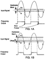
- FIG. 1A there is shown a sinusoidal input signal with common-mode noise impulses added.
- a hysteresis band having an upper voltage limit Vu and a lower voltage limit Vl is shown superimposed on an input signal to a trigger circuit.
- the output of the trigger circuit labeled Frequency Output, changes states as the input signal voltage passes across the hysteresis band.
- the width of the hysteresis band is narrow enough that the noise impulses present on the input signal can traverse the hysteresis band, causing undesired error pulses to be generated which corrupt an attempted frequency measurement of the signal.
- FIG. 1B the hysteresis band has been widened and its D.C. offset level adjusted to obtain an output from the trigger circuit that accurately reflects the actual frequency of the input signal free of errors from the noise impulses.
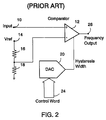
- FIG. 2 illustrates a prior art single comparator trigger circuit used to measure frequency in a handheld digital multimeter.
- the input signal is applied to an input terminal 10 which is coupled to the non inverting input of comparator 12.
- the D.C. offset of comparator 12 is created by coupling the inverting input of the comparator 12 to the center point of a voltage divider comprised of resistors 16 and 18 disposed in series between a stable reference voltage Vref coupled to a terminal 14 and ground.
- the actual D.C. offset voltage of the comparator is determined by the voltage divider ratio of the resistors 16 and 18 in the conventional manner.
- the hysteresis band width of the comparator 12 is determined by the value of an injected D.C. offset current.
- a digital-to-analog converter (DAC) 20 is coupled to the hysteresis width control input of the comparator 12 and generates a desired injection current corresponding to the desired hysteresis band width.
- the output of the comparator 12 is coupled to an output terminal 26 labeled Frequency Output which provides the trigger signal to subsequent frequency measurement circuits.
- the input signal is applied to an input terminal 28 which is coupled to the non inverting input of a comparator 30 and the inverting input of a comparator 32.
- a digital-to-analog converter (DAC) 34 which serves as a voltage reference for upper limit voltage Vu is coupled to the inverting input of the comparator 30.
- a digital-to-analog converter (DAC) 36 which serves as a voltage reference for lower limit voltage Vl is coupled to the non inverting input of the comparator 32.
- a digital control word received on a line 38 which can be provided by a microprocessor or digital controller, is used to program the DAC 34 and the DAC 36.
- a first input of a bistable circuit 42 is coupled to the output of comparator 30.
- a second input of bistable circuit 42 is coupled to the output of comparator 32.
- the comparator 30 provides a digital "high” to the first input of bistable circuit 42 thereby setting its output “high”.
- the digital "high” and “low” voltage levels correspond to industry-standard definitions for appropriate logic families such as TTL or CMOS.
- the comparator 32 provides a TTL-level "high” to the second input of bistable circuit 42 thereby resetting its output "low”.
- An output of bistable circuit 42 is coupled to an output terminal 48 labeled Frequency Output which provides the trigger signal to subsequent frequency measurement circuits.
- the input signal voltage level corresponds to a high or a low continuity level between the multimeter test leads, allowing the trigger circuit to provide a continuity detecting function.
- DAC 34 is set to a specified upper limit voltage to detect an "open" circuit between the multimeter test leads corresponding to a higher input signal level and DAC 36 is set to a specified lower signal level to detect a "short" circuit between the multimeter test leads corresponding to a lower input voltage level.
- An input of latch 40 is coupled to the output of the comparator 30.
- An input of latch 44 is coupled to the output of comparator 32.
- a read pulse is coupled to a terminal 52 which is coupled to latches 40 and 42 in order to enable the latches to store an output state of comparators 30 and 32 respectively when the read pulse is provided every 25 milliseconds.
- the outputs of the latch 40 and the latch 44 are coupled to output terminals 46 and 50 respectively which are in turn coupled to a microprocessor which enables or disables an audio tone responsive to the states stored in the latches 40 and 44.
Landscapes
- Physics & Mathematics (AREA)
- General Physics & Mathematics (AREA)
- Measurement Of Current Or Voltage (AREA)
- Manipulation Of Pulses (AREA)
- Measuring Instrument Details And Bridges, And Automatic Balancing Devices (AREA)
- Measuring Frequencies, Analyzing Spectra (AREA)
Applications Claiming Priority (2)
| Application Number | Priority Date | Filing Date | Title |
|---|---|---|---|
| US18063394A | 1994-01-13 | 1994-01-13 | |
| US180633 | 1994-01-13 |
Publications (2)
| Publication Number | Publication Date |
|---|---|
| EP0663597A2 true EP0663597A2 (de) | 1995-07-19 |
| EP0663597A3 EP0663597A3 (de) | 1997-03-05 |
Family
ID=22661170
Family Applications (1)
| Application Number | Title | Priority Date | Filing Date |
|---|---|---|---|
| EP94303713A Withdrawn EP0663597A3 (de) | 1994-01-13 | 1994-05-24 | Triggerschaltung mit zwei Komparatoren und unabhängige Spannungsabstimmung. |
Country Status (5)
| Country | Link |
|---|---|
| EP (1) | EP0663597A3 (de) |
| JP (1) | JPH07221613A (de) |
| KR (1) | KR0133983B1 (de) |
| CA (1) | CA2123773A1 (de) |
| TW (1) | TW250602B (de) |
Cited By (3)
| Publication number | Priority date | Publication date | Assignee | Title |
|---|---|---|---|---|
| US7652508B2 (en) | 2005-04-20 | 2010-01-26 | Sharp Kabushiki Kaisha | Circuit device and electronic equipment provided with the same |
| DE102010046098A1 (de) * | 2010-06-23 | 2011-12-29 | Rohde & Schwarz Gmbh & Co. Kg | Messvorrichtung mit einer Triggereinheit |
| WO2016007853A3 (en) * | 2014-07-10 | 2016-03-03 | Texas Instruments Incorporated | Dual-comparator circuit with dynamic vio shift protection |
Families Citing this family (7)
| Publication number | Priority date | Publication date | Assignee | Title |
|---|---|---|---|---|
| KR100468658B1 (ko) * | 1997-08-21 | 2005-03-16 | 페어차일드코리아반도체 주식회사 | 전원제어회로 |
| JP5432676B2 (ja) * | 2009-11-18 | 2014-03-05 | ルネサスエレクトロニクス株式会社 | マイクロコンピュータ、ヒステリシスコンパレータ回路、及び電圧監視装置 |
| JP5406146B2 (ja) * | 2010-08-31 | 2014-02-05 | 日立オートモティブシステムズ株式会社 | 電動駆動制御装置の過電流検出装置および過電流検出方法 |
| JP2013185844A (ja) * | 2012-03-06 | 2013-09-19 | Hioki Ee Corp | 電気測定装置 |
| JP2014109534A (ja) * | 2012-12-04 | 2014-06-12 | Hioki Ee Corp | 周波数測定装置および周波数測定方法 |
| JP6497025B2 (ja) * | 2013-10-17 | 2019-04-10 | ヤマハ株式会社 | 音声処理装置 |
| JP5628398B2 (ja) * | 2013-10-31 | 2014-11-19 | 日立オートモティブシステムズ株式会社 | 過電流検出装置 |
Family Cites Families (3)
| Publication number | Priority date | Publication date | Assignee | Title |
|---|---|---|---|---|
| JPS55128919A (en) * | 1979-03-28 | 1980-10-06 | Hitachi Denshi Ltd | Waveform shaping unit |
| EP0271202A3 (de) * | 1986-11-10 | 1989-12-13 | Hewlett-Packard Company | Triggerschaltung für ein Oszilloskop |
| US5223784A (en) * | 1991-06-01 | 1993-06-29 | Tektronix, Inc. | Method and circuit for triggering an electronic instrument only once during a period of a signal |
-
1994
- 1994-05-07 TW TW83104163A patent/TW250602B/zh active
- 1994-05-13 KR KR94010436A patent/KR0133983B1/ko not_active Expired - Fee Related
- 1994-05-17 CA CA 2123773 patent/CA2123773A1/en not_active Abandoned
- 1994-05-24 EP EP94303713A patent/EP0663597A3/de not_active Withdrawn
- 1994-10-07 JP JP27044594A patent/JPH07221613A/ja active Pending
Cited By (8)
| Publication number | Priority date | Publication date | Assignee | Title |
|---|---|---|---|---|
| US7652508B2 (en) | 2005-04-20 | 2010-01-26 | Sharp Kabushiki Kaisha | Circuit device and electronic equipment provided with the same |
| DE102010046098A1 (de) * | 2010-06-23 | 2011-12-29 | Rohde & Schwarz Gmbh & Co. Kg | Messvorrichtung mit einer Triggereinheit |
| WO2011160935A1 (de) * | 2010-06-23 | 2011-12-29 | Rohde & Schwarz Gmbh & Co. Kg | Messvorrichtung mit einer triggereinheit |
| US9250268B2 (en) | 2010-06-23 | 2016-02-02 | Rohde & Schwarz Gmbh & Co. Kg | Measuring device having a trigger unit |
| WO2016007853A3 (en) * | 2014-07-10 | 2016-03-03 | Texas Instruments Incorporated | Dual-comparator circuit with dynamic vio shift protection |
| US9383393B2 (en) | 2014-07-10 | 2016-07-05 | Texas Instruments Deutschland Gmbh | Dual-comparator circuit with dynamic VIO shift protection |
| CN106663989A (zh) * | 2014-07-10 | 2017-05-10 | 德州仪器公司 | 具有动态vio移位保护的双比较器电路 |
| CN106663989B (zh) * | 2014-07-10 | 2019-05-21 | 德州仪器公司 | 具有动态vio移位保护的双比较器电路 |
Also Published As
| Publication number | Publication date |
|---|---|
| CA2123773A1 (en) | 1995-07-14 |
| KR0133983B1 (en) | 1998-04-25 |
| TW250602B (en) | 1995-07-01 |
| EP0663597A3 (de) | 1997-03-05 |
| KR950024422A (ko) | 1995-08-21 |
| JPH07221613A (ja) | 1995-08-18 |
Similar Documents
| Publication | Publication Date | Title |
|---|---|---|
| US6380726B1 (en) | Smart auto-ranging RMS measurement method and apparatus | |
| US7054776B2 (en) | Apparatus for use in calibrating a VNA | |
| CA1133065A (en) | Method and apparatus for offset error correction | |
| US4336526A (en) | Successive approximation analog-to-digital converter using non-binary series | |
| EP0663597A2 (de) | Triggerschaltung mit zwei Komparatoren und unabhängige Spannungsabstimmung | |
| US7248058B2 (en) | Testing and calibration device with diagnostics | |
| JPH1054851A (ja) | 電源出力電流測定装置 | |
| JPH11174113A (ja) | Icテスタの電圧印加電流測定回路 | |
| US3934197A (en) | Automatic calibration system | |
| US4840066A (en) | Ultrasonic thickness gauge having automatic transducer recognition and parameter optimization and method thereof | |
| US6639539B1 (en) | System and method for extending the dynamic range of an analog-to-digital converter | |
| GB2141277A (en) | Electronic coin validator | |
| US4031533A (en) | Differential floating dual slope converter | |
| US9244111B2 (en) | Amperage/voltage loop calibrator with loop diagnostics | |
| EP0135214B1 (de) | Apparat zum Messen einer Temperatur | |
| HK1002224A (en) | Dual comparator trigger circuit with independent voltage level adjustment | |
| US11536616B2 (en) | Sensor device and method for operating a sensor device | |
| US6285206B1 (en) | Comparator circuit | |
| US3510770A (en) | Apparatus for the automatic calibration of digital instruments | |
| US4495462A (en) | Current source test circuitry | |
| EP0227248A2 (de) | Vorrichtung zur Anzeige der richtigen Kompensation eines justierbaren Frequenzkompensationsnetzwerkes | |
| JP2000252800A (ja) | 差動信号用比較器および差動信号比較方法 | |
| JPH07183346A (ja) | 半導体テスト装置 | |
| KR100352598B1 (ko) | 디지털멀티메터입력자동제어장치 | |
| TWI832652B (zh) | 電源量測裝置 |
Legal Events
| Date | Code | Title | Description |
|---|---|---|---|
| PUAI | Public reference made under article 153(3) epc to a published international application that has entered the european phase |
Free format text: ORIGINAL CODE: 0009012 |
|
| AK | Designated contracting states |
Kind code of ref document: A2 Designated state(s): DE FR GB NL |
|
| PUAL | Search report despatched |
Free format text: ORIGINAL CODE: 0009013 |
|
| AK | Designated contracting states |
Kind code of ref document: A3 Designated state(s): DE FR GB NL |
|
| 17P | Request for examination filed |
Effective date: 19970325 |
|
| STAA | Information on the status of an ep patent application or granted ep patent |
Free format text: STATUS: THE APPLICATION HAS BEEN WITHDRAWN |
|
| 18W | Application withdrawn |
Withdrawal date: 19990208 |
|
| REG | Reference to a national code |
Ref country code: HK Ref legal event code: WD Ref document number: 1002224 Country of ref document: HK |