EP0663721A1 - Filtre à ondes acoustiques de surface - Google Patents
Filtre à ondes acoustiques de surface Download PDFInfo
- Publication number
- EP0663721A1 EP0663721A1 EP95100185A EP95100185A EP0663721A1 EP 0663721 A1 EP0663721 A1 EP 0663721A1 EP 95100185 A EP95100185 A EP 95100185A EP 95100185 A EP95100185 A EP 95100185A EP 0663721 A1 EP0663721 A1 EP 0663721A1
- Authority
- EP
- European Patent Office
- Prior art keywords
- acoustic wave
- surface acoustic
- filter
- saw
- receiving
- Prior art date
- Legal status (The legal status is an assumption and is not a legal conclusion. Google has not performed a legal analysis and makes no representation as to the accuracy of the status listed.)
- Granted
Links
Images



Classifications
-
- H—ELECTRICITY
- H03—ELECTRONIC CIRCUITRY
- H03H—IMPEDANCE NETWORKS, e.g. RESONANT CIRCUITS; RESONATORS
- H03H9/00—Networks comprising electromechanical or electro-acoustic elements; Electromechanical resonators
- H03H9/46—Filters
- H03H9/64—Filters using surface acoustic waves
- H03H9/6423—Means for obtaining a particular transfer characteristic
- H03H9/6433—Coupled resonator filters
- H03H9/6483—Ladder SAW filters
-
- H—ELECTRICITY
- H03—ELECTRONIC CIRCUITRY
- H03H—IMPEDANCE NETWORKS, e.g. RESONANT CIRCUITS; RESONATORS
- H03H9/00—Networks comprising electromechanical or electro-acoustic elements; Electromechanical resonators
- H03H9/46—Filters
- H03H9/64—Filters using surface acoustic waves
Definitions
- the present invention relates to a surface acoustic wave filter utilizing a surface acoustic wave resonator. More particularly, the present invention relates to a surface acoustic wave filter which handles signals having a large electric power in a high frequency region.
- SAW filters have been positively developed with the recent development in mobile communications in which signals of higher frequencies are used.
- Typical known methods include, for example: a method for configuring a filter using a plurality of SAW resonators as described in Japanese Laid-Open Patent Publication No. 52-19044; a method for configuring a filter in which each of input and output interdigital transducers of a SAW resonator is divided into a plurality of portions (such a structure is called an interdigitated interdigital transducer structure) as described in Japanese Laid-Open Patent Publication No. 58-154917; and a method for configuring a filter in which SAW resonators are disposed adjacently and capacitively coupled to each other as described in Japanese Laid-Open patent Publication No. 3-222512.
- SAW filters are required to have a smaller size and an improved performance, in accordance with the miniaturization of mobile communication apparatus in recent years. In addition, SAW filters are more often used in various portions of the mobile communication apparatus.
- Mobile communication apparatus used in a communication system in which signals are simultaneously transmitted and received has a transmitting circuit and a receiving circuit which are connected to each other.
- a SAW filter may be used as a receiving filter included in the receiving circuit of the communication apparatus having the above-described configuration.
- a SAW resonator constituting the SAW filter may be deteriorated in a relatively short period of time. This may disadvantageously result in deterioration of the filter characteristics. Accordingly, there exits a problem in that, if the SAW filter is used as a receiving filter in a communication apparatus capable of simultaneously transmitting and receiving signals, desired advantages cannot be attained.
- a surface acoustic wave filter to be used in a receiving circuit of a communication apparatus capable of simultaneously transmitting a first signal having a predetermined transmitting frequency and receiving a second signal having a predetermined receiving frequency which is lower than the transmitting frequency, includes: an input terminal for receiving an input signal; an output terminal for providing an output signal; and a plurality of surface acoustic wave resonators, wherein the plurality of surface acoustic wave resonators include: at least one series surface acoustic wave resonator connected in series to a signal line connecting the input terminal and the output terminal; and at least two parallel surface acoustic wave resonators each connected between a ground and respective predetermined positions in the signal line, and wherein one of the at least two parallel surface acoustic wave resonators is disposed most closely to the input terminal among the plurality of surface acoustic wave resonators.
- a surface acoustic wave filter to be used in a receiving circuit of a communication apparatus capable of simultaneously transmitting a first signal having a predetermined transmitting frequency and receiving a second signal having a predetermined receiving frequency which is higher than the transmitting frequency, includes: an input terminal for receiving an input signal; an output terminal for providing an output signal; and a plurality of surface acoustic wave resonators, wherein the plurality of surface acoustic wave resonators include: at least two series surface acoustic wave resonators each connected in series to a signal line connecting the input terminal and the output terminal; and at least one parallel surface acoustic wave resonator connected between a ground and a predetermined position in the signal line, and wherein one of the at least two series surface acoustic wave resonators is disposed most closely to the input terminal among the plurality of surface acoustic wave resonators.
- each of the plurality of surface acoustic wave resonators is configured using a lithium tantalate substrate.
- an interdigital transducer included in each of the plurality of surface acoustic wave resonators is formed with aluminum which contains copper of 0.5 to 3 wt%.
- the invention described herein makes possible the advantage of providing a SAW filter having filter characteristics which are not deteriorated by the application of electric power outside of its pass band, whereby the SAW filter being applicable to a filter in a receiving circuit of a mobile communication apparatus capable of simultaneously transmitting and receiving signals.
- Figure 1 is a block diagram schematically showing an exemplary configuration of a transmitting circuit and a receiving circuit in a mobile communication apparatus capable of simultaneously transmitting and receiving signals.
- Figure 2 is a graph schematically showing the relationship between an impedance (imaginary part) and a frequency of series/parallel SAW resonators which constitute a resonator-type filter.
- Figure 3 is a diagram schematically showing the configuration of a SAW filter in a first example according to the invention.
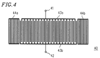
- Figure 4 is a diagram showing an exemplary configuration of a SAW resonator used in the SAW filter according to the invention.
- Figure 5 is a diagram schematically showing the configuration of a SAW filter in a second example according to the invention.
- Figure 1 is a block diagram schematically showing an exemplary configuration of a transmitting circuit and a receiving circuit for high-frequency signals in a mobile communication apparatus capable of simultaneously transmitting and receiving signals.
- a high-frequency transmitting signal generated in an oscillator 10 is conveyed through a mixer 5 , a first transmitting filter 4 , a power amplifier 3 , and a second transmitting filter 2 included in a transmitting circuit and then transmitted from an antenna 1 .
- a high-frequency signal received at the antenna 1 is fed through a second receiving filter 6 , a receiving amplifier 7 , a first receiving filter 8 , and a mixer 9 included in a receiving circuit.
- a control unit 11 controls the operation of these transmitting and receiving circuits.
- SAW filters are mainly used as the first transmitting filter 4 functioning as an inter-stage filter in the transmitting circuit, the first receiving filter 8 functioning as an inter-stage filter in the receiving circuit, the second transmitting filter 2 functioning as an output filter of the oscillator 10 , and the like. Furthermore, a SAW filter may be used as the second receiving filter 6 corresponding to an initial stage input of the receiving circuit.
- the receiving circuit and the transmitting circuit are connected to each other. Accordingly, a transmitting signal is transmitted to the outside through the antenna 1 and also is applied to circuit elements constituting the receiving circuit, especially to the second receiving filter 6 which is disposed most closely to the antenna 1 . It is considered that most of the transmitting signals applied to the receiving circuit are reflected by the SAW resonator which constitutes the second receiving filter 6 .
- a transmitting signal has a relatively large electric power.
- the frequency of the transmitting signal generally exists outside of the pass band of the SAW filter serving as the second receiving filter 6 . Accordingly, the transmitting signal which is to be applied to the second receiving filter 6 is an out-of-band applied electric power for the SAW filter serving as the second receiving filter 6 , when applied thereto.
- the transmitting signal i.e., the out-of-band applied electric power has a frequency coinciding with a singular point of the SAW resonator, that is, a frequency corresponding to the resonance frequency or the antiresonance frequency of the SAW resonator
- the electric power seriously adversely affects the durability of the SAW resonator. The reasons are explained with reference to Figure 2 .
- Figure 2 shows the relationship between an impedance (imaginary part) and a frequency for a series SAW resonator and a parallel SAW resonator which constitute the resonator-type filter.
- point B on an impedance curve for the parallel SAW resonator indicates the antiresonance frequency of the parallel SAW resonator.
- point C on an impedance curve for the series SAW resonator indicates the resonance frequency thereof.
- the frequency region between the points B and C corresponds to the pass band of the SAW filter constituted by the series and parallel SAW resonators.
- the second receiving filter 6 when a parallel SAW resonator, which is connected between a signal line and a ground, is disposed most closely to the antenna 1 , a resonance point (point A in Figure 2 ) as the singular point exists in a frequency region lower than the pass band. At the resonance point A , the impedance is close to 0, so that a large current flows through the parallel SAW resonator. Accordingly, when a signal having a frequency around the resonance point A is applied to the parallel SAW resonator, the parallel SAW resonator may be deteriorated by the large current.
- an antiresonance point (point D in Figure 2 ) as the singular point exists in a frequency region higher than the pass band.
- the impedance is very large, so that a large voltage is applied to the series SAW resonator. Accordingly, when a signal having a frequency around the antiresonance point D is applied to the series SAW resonator, the series SAW resonator may be deteriorated by the large voltage.
- the inventors found that in a desired filter configuration, the singular point of the SAW resonator used in the second receiving filter 6 shown in Figure 1 should be prevented from coinciding with the frequency of the transmitting signal in order to prevent the deterioration of the SAW resonator.
- the second receiving filter 6 is configured in such a manner that a particular SAW resonator disposed most closely to the input terminal is connected between the signal line and the ground, so as to form a parallel resonator.
- the second receiving filter 6 is configured in such a manner that a particular SAW resonator disposed most closely to the input terminal is connected in series to the signal line, so as to form a series resonator.
- FIG. 3 schematically shows the configuration of a SAW filter 100 in a first example according to the invention.
- the SAW filter 100 in this example is used in the case where the transmitting frequency is higher than the receiving frequency, that is, in the case where the transmitting signal to be an out-of-band electric power applied to the second receiving filter 6 has a frequency higher than the pass band of the second receiving filter 6 .
- the SAW filter 100 includes two series SAW resonators 101a and 101b connected in series to a signal line connecting an input terminal 103 and an output terminal 104 , and three parallel SAW resonators 102a , 102b and 102c connected between the signal line and a ground.
- the parallel SAW resonators the first parallel SAW resonator 102a is connected between a node of the input terminal 103 and the first series SAW resonator 101a , and the ground.
- the second parallel SAW resonator 102b is connected between a node of the first series SAW resonator 101a and the second series SAW resonator 101b , and the ground.
- the third parallel SAW resonator 102c is connected between a node of the second series SAW resonator 101b and the output terminal 104 , and the ground.
- the SAW resonator which is disposed most closely to the input terminal 103 is the first parallel SAW resonator 102a .
- FIG. 4 shows an exemplary configuration of each of the SAW resonators 101a , 101b , 102a , 102b and 102c .
- a SAW resonator 40 shown in Figure 4 has a configuration in which two interdigital transducers (hereinafter referred to as IDTs) 43a and 43b which are coupled to each other are interposed between two reflectors 44a and 44b .
- the IDT 43a is connected to an input terminal 41 and the IDT 43b is connected to an output terminal 42 .
- a pure aluminum film is deposited on a surface of a 36° Y-cut X-propagation lithium tantalate substrate by sputtering in a predetermined pattern.
- the IDTs 43a and 43b , and the reflectors 44a and 44b are formed.
- the fabrication method of the IDTs 43a and 43b and the reflectors 44a and 44b is not limited to that described above.
- a material other than pure aluminum can be used.
- the SAW resonator 40 can be formed on a substrate of another type, such as 41° Y-cut X-propagation lithium niobate substrate. Moreover, disposing all SAW resonators, included in one filter, on one and the same substrate is advantageous in terms of the simplification of the fabrication process and a reduction in statistic variation of characteristics between the respective SAW resonators.
- the configuration and the fabricating method of the SAW resonator 40 , or the characteristics of the SAW resonator 40 are well known, so that the detailed descriptions thereof are omitted.
- typical design parameters are as follows: the number of IDT pairs is 100; the pitch of the IDTs is 1.101 ⁇ m; a length of aperture of the IDTs is 50 ⁇ m; and the number of branches of the reflector is 50.
- the SAW resonator 40 having the configuration shown in Figure 4 is used for the parallel SAW resonators 102a , 102b and 102c in the SAW filter 100 shown in Figure 3
- typical design parameters are as follows: the number of IDT pairs is 100; the pitch of the IDTs is 1.155 ⁇ m; the length of aperture of the IDTs is 130 ⁇ m; and the number of branches of the reflector is 50.
- the thickness of the pure aluminum film is set to be 4100 ⁇ .
- the pass band of the filter can be set to about 858 MHz to 887 MHz, and the central frequency of the pass band can be set to about 872 MHz. It is appreciated that the above values are only examples, and another configuration with other values can be realized.
- a SAW filter may have at least one series SAW resonator and at least two parallel SAW resonators, as long as these SAW resonators are disposed so as to satisfy the above-described positional relationship.
- a larger number of series SAW resonators and a larger number of parallel SAW resonators can be connected.
- FIG. 5 schematically shows the configuration of a SAW filter 200 in a second example according to the invention.
- the SAW filter 200 in this example is used in the case where the transmitting frequency is lower than the receiving frequency, that is, in the case where the transmitting signal to be an out-of-band electric power applied to the second receiving filter 6 has a frequency lower than the pass band of the second receiving filter 6 .
- the SAW filter 200 includes three series SAW resonators 201a , 201b and 201c connected in series to a signal line between an input terminal 203 and an output terminal 204 , and two parallel SAW resonators 202a and 202b connected between the signal line and a ground.
- the first parallel SAW resonator 202a is connected between a node of the first series SAW resonator 201a and the second series SAW resonator 201b , and the ground.
- the second parallel SAW resonator 202b is connected between a node of the second series SAW resonator 201b and the third series SAW resonator 201c , and the ground.
- the SAW resonator which is disposed most closely to the input terminal 203 is the first series SAW resonator 201a .
- the respective SAW resonators 201a , 201b , 201c , 202a and 202b are configured as shown in Figure 4 as in the first example. Accordingly, the detailed descriptions on the fabrication process and the configuration, or the characteristics are omitted here.
- typical design parameters are as follows: the number of IDT pairs is 100; the pitch of the IDTs is 1.101 ⁇ m; a length of aperture of the IDTs is 50 ⁇ m; and the number of branches of the reflector is 50.
- the SAW resonator 40 having the configuration shown in Figure 4 is used for the parallel SAW resonators 202a and 202b in the SAW filter 200 shown in Figure 5
- typical design parameters are as follows: the number of IDT pairs is 100; the pitch of the IDTs is 1.155 ⁇ m; the length of aperture of the IDTs is 130 ⁇ m; and the number of branches of the reflector is 50.
- the thickness of the pure aluminum film is set to be 4100 ⁇ .
- the pass band of the filter can be set to about 858 MHz to 887 MHz, and the central frequency of the pass band can be set to about 872 MHz. It is appreciated that the above values are only examples, and another configuration with other values can be realized.
- a signal having a frequency of 827 MHz, which is lower than the central frequency of the pass band by about 45 MHz, and an electric power of 4 W is applied to the SAW filter 200 at an ambient temperature of 100°C for 200 hours.
- the filter characteristics such as a pass characteristic, a reflection characteristic, and the like, in the SAW filter 200 having the configuration shown in Figure 5 after the elapse of 200 hours.
- a SAW filter may have at least two series SAW resonators and at least one parallel SAW resonator, as long as these SAW resonators are disposed so as to satisfy the above-described positional relationship.
- a larger number of series SAW resonators and a larger number of parallel SAW resonators can be connected.
- the advantages of the SAW filters 100 and 200 which are described in the first and second examples, respectively, can be further verified by the following comparative study.
- the signal described in the second example having a frequency of 827 MHz which is lower than the center frequency of the pass band by about 45 MHz and an electric power of 4 W, is applied, at an ambient temperature of 100°C for 200 hours, to the SAW filter 100 having the configuration of Figure 3 described in the first example.
- the signal described in the first example having a frequency of 917 MHz which is higher than the central frequency of the pass band by about 45 MHz and an electric power of 4 W, is applied, at an ambient temperature of 100°C for 200 hours, to the SAW filter 200 having the configuration of Figure 5 described in the second example.
- each SAW resonator is the same as that shown in Figure 4 and described in the first and second examples, so that the detailed description thereof is omitted.
- a SAW filter having the configuration shown in Figure 3 is configured.
- the SAW resonator disposed most closely to the input terminal through which a signal is applied to the filter is the parallel SAW resonator.
- the design parameters of each SAW resonator are selected as described in the previous examples so that the pass band of the filter is about 858 MHz to 887 MHz, and the central frequency of the pass band is about 872 MHz.
- the content of copper is varied.
- aluminum which contains copper of 0.5 to 3 wt% similar advantages can be attained as in the case where aluminum which contains copper of 1 wt% is used.
- the content of copper is lower than 0.5 wt%, the advantages cannot be attained.
- the content of copper is higher than 3 wt%, serious deterioration of filter characteristics occurs due to the increase in electric resistance.
- the advantages of the SAW filter of the invention can be further improved by enhancing durability thereof by using aluminum which contains copper of 0.5 to 3 wt% as a material for the IDTs and reflectors of the SAW resonators.
- the SAW resonator connected most closely to the input terminal of the filter is the parallel SAW resonator as in the first example. It is appreciated that the same advantages can be attained in the case where the SAW resonator connected most closely to the input terminal of the filter is the series SAW resonator as in the second example.
Landscapes
- Physics & Mathematics (AREA)
- Acoustics & Sound (AREA)
- Surface Acoustic Wave Elements And Circuit Networks Thereof (AREA)
Applications Claiming Priority (2)
| Application Number | Priority Date | Filing Date | Title |
|---|---|---|---|
| JP1476/94 | 1994-01-12 | ||
| JP00147694A JP3375712B2 (ja) | 1994-01-12 | 1994-01-12 | 弾性表面波フィルタ |
Publications (2)
| Publication Number | Publication Date |
|---|---|
| EP0663721A1 true EP0663721A1 (fr) | 1995-07-19 |
| EP0663721B1 EP0663721B1 (fr) | 1998-11-25 |
Family
ID=11502510
Family Applications (1)
| Application Number | Title | Priority Date | Filing Date |
|---|---|---|---|
| EP95100185A Expired - Lifetime EP0663721B1 (fr) | 1994-01-12 | 1995-01-09 | Filtre à ondes acoustiques de surface |
Country Status (4)
| Country | Link |
|---|---|
| US (1) | US5589806A (fr) |
| EP (1) | EP0663721B1 (fr) |
| JP (1) | JP3375712B2 (fr) |
| DE (1) | DE69506137T2 (fr) |
Cited By (5)
| Publication number | Priority date | Publication date | Assignee | Title |
|---|---|---|---|---|
| EP0758819A1 (fr) * | 1995-08-14 | 1997-02-19 | Murata Manufacturing Co., Ltd. | Filtre à ondes acoustiques de surface |
| FR2738088A1 (fr) * | 1995-08-24 | 1997-02-28 | Fujitsu Ltd | Dispositif de filtre et systeme de radio a deux bandes dans lequel le dispositif de filtre est utilise |
| WO1998012806A1 (fr) * | 1996-09-19 | 1998-03-26 | Siemens Matsushita Components Gmbh & Co. Kg | Filtre a reactance comportant des resonateurs a onde de surface |
| US6891449B2 (en) * | 2000-04-03 | 2005-05-10 | Matsushita Electric Industrial Co., Ltd. | Antenna duplexer |
| EP1326333A3 (fr) * | 1997-02-12 | 2007-10-17 | Oki Electric Industry Co., Ltd. | Filtres à ondes acoustiques de surface comportant des pôles d'atténuation, crées par des circuits d'impédance |
Families Citing this family (10)
| Publication number | Priority date | Publication date | Assignee | Title |
|---|---|---|---|---|
| EP0746095B1 (fr) * | 1995-05-29 | 2007-02-14 | SANYO ELECTRIC Co., Ltd. | Filtre à ondes acoustiques de surface |
| WO1999060700A1 (fr) * | 1998-05-19 | 1999-11-25 | Matsushita Eletric Industrial Co., Ltd. | Filtre a onde acoustique de surface, dispositif de partage d'antenne comprenant ce filtre et terminal de communication mobile comprenant ce filtre |
| JP3498204B2 (ja) * | 1999-03-10 | 2004-02-16 | 株式会社村田製作所 | 弾性表面波フィルタ、それを用いた通信機装置 |
| JP3432492B2 (ja) * | 2000-09-28 | 2003-08-04 | 富士通株式会社 | 弾性表面波共振器及びこれを用いた弾性表面波フィルタ |
| US7299528B2 (en) * | 2002-11-05 | 2007-11-27 | Lee David M | Method for forming a multi-frequency surface acoustic wave device |
| JP2004228911A (ja) * | 2003-01-22 | 2004-08-12 | Tdk Corp | 分波器 |
| US7446629B2 (en) * | 2004-08-04 | 2008-11-04 | Matsushita Electric Industrial Co., Ltd. | Antenna duplexer, and RF module and communication apparatus using the same |
| KR100760780B1 (ko) * | 2004-09-28 | 2007-09-21 | 후지쓰 메디아 데바이스 가부시키가이샤 | 분파기 |
| JP2011205625A (ja) * | 2010-03-02 | 2011-10-13 | Panasonic Corp | ラダー型フィルタ |
| US9853624B2 (en) * | 2015-06-26 | 2017-12-26 | Qorvo Us, Inc. | SAW resonator with resonant cavities |
Citations (1)
| Publication number | Priority date | Publication date | Assignee | Title |
|---|---|---|---|---|
| EP0422637A2 (fr) * | 1989-10-13 | 1991-04-17 | Hitachi, Ltd. | Dispositif à ondes acoustiques de surface et appareil de communication |
Family Cites Families (14)
| Publication number | Priority date | Publication date | Assignee | Title |
|---|---|---|---|---|
| US4166258A (en) * | 1974-08-29 | 1979-08-28 | International Business Machines Corporation | Thin-film integrated circuit with tank circuit characteristics and applications to thin-film filters and oscillators |
| JPS5219044A (en) * | 1975-08-04 | 1977-01-14 | Nippon Telegr & Teleph Corp <Ntt> | Surface acoustic wave filter |
| JPS58154917A (ja) * | 1982-03-10 | 1983-09-14 | Hitachi Ltd | 弾性表面波バンドパスフイルタ |
| DE3407480A1 (de) * | 1984-02-29 | 1985-09-05 | Siemens AG, 1000 Berlin und 8000 München | Elektrisches oberflaechenwellenfilter |
| US4673901A (en) * | 1984-10-26 | 1987-06-16 | Siemens Aktiengesellschaft | Electrical filter operating with acoustic waves |
| DE3517254A1 (de) * | 1985-05-13 | 1986-11-13 | Siemens AG, 1000 Berlin und 8000 München | Mit akustischen wellen arbeitendes elektrisches filter |
| JPS63132515A (ja) * | 1986-11-25 | 1988-06-04 | Hitachi Ltd | 弾性表面波複合フイルタ |
| JPH03222512A (ja) * | 1990-01-29 | 1991-10-01 | Oki Electric Ind Co Ltd | 有極形saw共振器フィルタ |
| JPH03278608A (ja) * | 1990-03-28 | 1991-12-10 | Hitachi Ltd | 多段縦続接続型弾性表面波フィルタ及びそれを用いた通信装置 |
| JPH04253414A (ja) * | 1991-01-30 | 1992-09-09 | Hitachi Ltd | 弾性表面波共振器複合形フィルタを用いた分波器 |
| JP2800905B2 (ja) * | 1991-10-28 | 1998-09-21 | 富士通株式会社 | 弾性表面波フィルタ |
| JPH061783A (ja) * | 1992-06-17 | 1994-01-11 | Mitsubishi Rayon Co Ltd | 有機酸エステルの製造法 |
| JPH0613833A (ja) * | 1992-06-24 | 1994-01-21 | Murata Mfg Co Ltd | 弾性表面波素子 |
| JP3194540B2 (ja) * | 1992-07-13 | 2001-07-30 | 富士通株式会社 | 弾性表面波フィルタ |
-
1994
- 1994-01-12 JP JP00147694A patent/JP3375712B2/ja not_active Expired - Fee Related
-
1995
- 1995-01-05 US US08/368,981 patent/US5589806A/en not_active Expired - Lifetime
- 1995-01-09 EP EP95100185A patent/EP0663721B1/fr not_active Expired - Lifetime
- 1995-01-09 DE DE69506137T patent/DE69506137T2/de not_active Expired - Lifetime
Patent Citations (1)
| Publication number | Priority date | Publication date | Assignee | Title |
|---|---|---|---|---|
| EP0422637A2 (fr) * | 1989-10-13 | 1991-04-17 | Hitachi, Ltd. | Dispositif à ondes acoustiques de surface et appareil de communication |
Non-Patent Citations (2)
| Title |
|---|
| IEKI H ET AL: "SAW RESONATORS USING EPITAXIALLY GROWN AL ELECTRODES", JAPANESE JOURNAL OF APPLIED PHYSICS, SUPPLEMENTS, vol. SUPPL.30, no. 30, pages 176 - 178, XP000305677 * |
| MITSUTAKA HIKITA ET AL: "Investigation of new low-loss and high-power SAW filters for reverse-frequency-allocated cellular radios", IEEE TRANSACTIONS ON ULTRASONICS, FERROELECTRICS AND FREQUENCY CONTROL, vol. 40, no. 3, NEW YORK US, pages 224 - 231, XP000382841, DOI: doi:10.1109/58.216835 * |
Cited By (8)
| Publication number | Priority date | Publication date | Assignee | Title |
|---|---|---|---|---|
| EP0758819A1 (fr) * | 1995-08-14 | 1997-02-19 | Murata Manufacturing Co., Ltd. | Filtre à ondes acoustiques de surface |
| US5831493A (en) * | 1995-08-14 | 1998-11-03 | Murata Manufacturing Co., Ltd. | Surface acoustic wave ladder filter utilizing a generated spurious component of the parallel arm |
| FR2738088A1 (fr) * | 1995-08-24 | 1997-02-28 | Fujitsu Ltd | Dispositif de filtre et systeme de radio a deux bandes dans lequel le dispositif de filtre est utilise |
| US6115592A (en) * | 1995-08-24 | 2000-09-05 | Fujitsu Limited | Filter device and dual-band radio system in which the filter device is used |
| WO1998012806A1 (fr) * | 1996-09-19 | 1998-03-26 | Siemens Matsushita Components Gmbh & Co. Kg | Filtre a reactance comportant des resonateurs a onde de surface |
| US6246302B1 (en) | 1996-09-19 | 2001-06-12 | Siemens Matsushita Components Gmbh & Co. Kg | Reactance filter with surface wave resonators |
| EP1326333A3 (fr) * | 1997-02-12 | 2007-10-17 | Oki Electric Industry Co., Ltd. | Filtres à ondes acoustiques de surface comportant des pôles d'atténuation, crées par des circuits d'impédance |
| US6891449B2 (en) * | 2000-04-03 | 2005-05-10 | Matsushita Electric Industrial Co., Ltd. | Antenna duplexer |
Also Published As
| Publication number | Publication date |
|---|---|
| US5589806A (en) | 1996-12-31 |
| JPH07212182A (ja) | 1995-08-11 |
| DE69506137D1 (de) | 1999-01-07 |
| EP0663721B1 (fr) | 1998-11-25 |
| DE69506137T2 (de) | 1999-05-12 |
| JP3375712B2 (ja) | 2003-02-10 |
Similar Documents
| Publication | Publication Date | Title |
|---|---|---|
| EP0664610B1 (fr) | Filtre à ondes acoustiques de surface | |
| KR100434411B1 (ko) | 탄성 표면파 장치 | |
| EP0663721B1 (fr) | Filtre à ondes acoustiques de surface | |
| US7902940B2 (en) | Duplexer | |
| EP0998039B1 (fr) | Filtre d'ondes acoustiques de surface | |
| US6522219B2 (en) | Surface acoustic wave ladder filter with two series resonators having different apodization weighting | |
| US5844453A (en) | Surface acoustic wave filter utilizing a transducer having interdigital electrodes and continuously adjacent electrodes | |
| US6255916B1 (en) | Resonator-type surface-acoustic-wave filter for reducing the signal strength of a spurious peak | |
| EP0782255B1 (fr) | Filtre résonateur à ondes acoustiques de surface à couplage longitudinal | |
| US7532090B2 (en) | Acoustic wave filter device and duplexer | |
| EP0757438B1 (fr) | Dispositif à ondes acoustiques de surface | |
| EP1049254A2 (fr) | Résonateur à ondes acoustiques de surface, filtre composite à ondes acoustiques de surface et filtre à ondes acoustiques de surface | |
| EP1005153B1 (fr) | Filtre à ondes acoustiques de surface | |
| JP3873802B2 (ja) | 弾性表面波フィルタ | |
| JPH07283682A (ja) | 弾性表面波共振子フィルタ | |
| JP3838128B2 (ja) | 弾性表面波装置、および、これを搭載した通信装置 | |
| EP1005154B1 (fr) | Filtre à ondes acoustiques de surface pour l'amélioration de la planéité de la bande passante et procédé de fabrication du même | |
| JP3739858B2 (ja) | 高周波フィルタ | |
| US6366179B1 (en) | Surface acoustic wave element having two filters with more IDTs in the lower frequency filter | |
| JPH11312951A (ja) | 弾性表面波フィルタ | |
| US6720847B2 (en) | Longitudinally-coupled resonator surface acoustic wave filter and communication apparatus using the same | |
| JP2002232264A (ja) | 弾性表面波フィルタ | |
| JP3878714B2 (ja) | 弾性表面波フィルタ | |
| JPH09181565A (ja) | 弾性表面波フィルタ装置 | |
| WO1998034345A1 (fr) | Resonateur couple en ligne comportant un filtre en treillis et procede afferent |
Legal Events
| Date | Code | Title | Description |
|---|---|---|---|
| PUAI | Public reference made under article 153(3) epc to a published international application that has entered the european phase |
Free format text: ORIGINAL CODE: 0009012 |
|
| 17P | Request for examination filed |
Effective date: 19950109 |
|
| AK | Designated contracting states |
Kind code of ref document: A1 Designated state(s): DE GB SE |
|
| GRAG | Despatch of communication of intention to grant |
Free format text: ORIGINAL CODE: EPIDOS AGRA |
|
| GRAG | Despatch of communication of intention to grant |
Free format text: ORIGINAL CODE: EPIDOS AGRA |
|
| GRAH | Despatch of communication of intention to grant a patent |
Free format text: ORIGINAL CODE: EPIDOS IGRA |
|
| 17Q | First examination report despatched |
Effective date: 19980414 |
|
| GRAH | Despatch of communication of intention to grant a patent |
Free format text: ORIGINAL CODE: EPIDOS IGRA |
|
| GRAA | (expected) grant |
Free format text: ORIGINAL CODE: 0009210 |
|
| AK | Designated contracting states |
Kind code of ref document: B1 Designated state(s): DE GB SE |
|
| REF | Corresponds to: |
Ref document number: 69506137 Country of ref document: DE Date of ref document: 19990107 |
|
| PLBE | No opposition filed within time limit |
Free format text: ORIGINAL CODE: 0009261 |
|
| STAA | Information on the status of an ep patent application or granted ep patent |
Free format text: STATUS: NO OPPOSITION FILED WITHIN TIME LIMIT |
|
| 26N | No opposition filed | ||
| REG | Reference to a national code |
Ref country code: GB Ref legal event code: IF02 |
|
| PGFP | Annual fee paid to national office [announced via postgrant information from national office to epo] |
Ref country code: GB Payment date: 20130109 Year of fee payment: 19 Ref country code: SE Payment date: 20130114 Year of fee payment: 19 Ref country code: DE Payment date: 20130103 Year of fee payment: 19 |
|
| REG | Reference to a national code |
Ref country code: DE Ref legal event code: R119 Ref document number: 69506137 Country of ref document: DE |
|
| REG | Reference to a national code |
Ref country code: SE Ref legal event code: EUG |
|
| GBPC | Gb: european patent ceased through non-payment of renewal fee |
Effective date: 20140109 |
|
| REG | Reference to a national code |
Ref country code: DE Ref legal event code: R119 Ref document number: 69506137 Country of ref document: DE Effective date: 20140801 |
|
| PG25 | Lapsed in a contracting state [announced via postgrant information from national office to epo] |
Ref country code: DE Free format text: LAPSE BECAUSE OF NON-PAYMENT OF DUE FEES Effective date: 20140801 |
|
| PG25 | Lapsed in a contracting state [announced via postgrant information from national office to epo] |
Ref country code: GB Free format text: LAPSE BECAUSE OF NON-PAYMENT OF DUE FEES Effective date: 20140109 Ref country code: SE Free format text: LAPSE BECAUSE OF NON-PAYMENT OF DUE FEES Effective date: 20140110 |