EP0664155A1 - Agitateur - Google Patents
Agitateur Download PDFInfo
- Publication number
- EP0664155A1 EP0664155A1 EP95100723A EP95100723A EP0664155A1 EP 0664155 A1 EP0664155 A1 EP 0664155A1 EP 95100723 A EP95100723 A EP 95100723A EP 95100723 A EP95100723 A EP 95100723A EP 0664155 A1 EP0664155 A1 EP 0664155A1
- Authority
- EP
- European Patent Office
- Prior art keywords
- stirring element
- approximately
- angle
- stirring
- range
- Prior art date
- Legal status (The legal status is an assumption and is not a legal conclusion. Google has not performed a legal analysis and makes no representation as to the accuracy of the status listed.)
- Granted
Links
Images


Classifications
-
- B—PERFORMING OPERATIONS; TRANSPORTING
- B01—PHYSICAL OR CHEMICAL PROCESSES OR APPARATUS IN GENERAL
- B01F—MIXING, e.g. DISSOLVING, EMULSIFYING OR DISPERSING
- B01F27/00—Mixers with rotary stirring devices in fixed receptacles; Kneaders
- B01F27/05—Stirrers
- B01F27/11—Stirrers characterised by the configuration of the stirrers
- B01F27/113—Propeller-shaped stirrers for producing an axial flow, e.g. shaped like a ship or aircraft propeller
Definitions
- the invention relates to a stirrer for stirring in particular low and medium viscosity liquids, with an attachment to a stirrer shaft and an inner main blade and an outer side blade connected thereto.
- the main blade of the stirrer is attached to a stirrer shaft on the inside (at the end facing away from the side blade) and the side blade is attached to the outside.
- Stirring devices with stirring blades are known whose blade width is constant or tapers towards the tip of the blade.
- Propeller stirrers with stirring blades with symmetrical, hanging or trailing blade shapes are also known.
- the disadvantage here is the high cost of materials and also the difficult to manufacture.
- the axial velocities are more or less evenly distributed in the outflow surface.
- the invention therefore aims to provide a stirring element of the type mentioned at the outset, which has a high hydraulic efficiency, while reducing the difficulties described above.
- this is achieved in that the side blade - in axial section - forms an angle ⁇ 0 to the main blade, and that the main blade is made at an angle ⁇ 0 to the plane of rotation of the stirring element.
- the ratio of the tangential length of the side blade to the outer diameter of the stirring element is preferably in the range from about 0.15 to about 0.4.
- the angle ⁇ 0 is preferably in the range from approximately -25 ° to approximately + 25 ° and the angle of attack ⁇ 0 is preferably in the range from approximately 15 ° to approximately 29 °.
- the main blade is bent along a radial line or a line extending at an acute angle ⁇ to it by an angle ⁇ 1 relative to the first section of the main blade, which is set at the angle of attack ⁇ 0.
- angles ⁇ 1, ⁇ 2 and ⁇ 3 are preferably in the range from about 7 ° to about 19 °.
- the main blade is at least partially curved in the tangential section, it being possible for further curved sections of different curvature to be connected to a flat section set at the angle of incidence ⁇ 0 to the plane of rotation.
- the ratio of the radii of these curvatures to the outer diameter of the stirring element is preferably in the range from about 0.15 to about 0.8.
- the side sheet in the axial section is single or multiple kinked or curved.
- the curvature can comprise several sections with different radii, the ratio of these radii to the outside diameter of the stirring element preferably being in the range from about 0.1 to about 0.8.
- the connecting line between the main sheet and the side sheet can expediently form an angle of about 70 ° to about 95 ° to the radial center line of the main sheet, while the tangential center line of the side sheet can preferably form an angle of 60 ° to 110 ° to the radial center line of the main sheet .
- the outer edge or outer contour of the side blade is advantageously adapted to the circumferential line of the stirring element or runs along this circumferential line.
- the stirring element 10 has, for example, a hub 12 for attachment to a stirrer shaft, not shown, and a radially inner main blade 14 and an outer side blade 16.
- the main blade 14 can be welded directly to the hub 12 with or without an additional fastening element, for example in the form of a spar 18 connected to the hub.
- the side blade 16 is fixedly connected to the main blade 14, for example by welding, or both blades 14, 16 are formed in one piece, for example cast or formed from a flat piece of sheet metal.
- the thickness of the two stirring blades 14, 16 can be of the same design or the outer blade 16 can be made with a reduced blade thickness.
- the two stirring blades 14, 16 have a common front edge 20 which, in the embodiment shown, runs parallel to a radial line R which passes through the center of the hub 12, which serves as an attachment, for example.
- a connecting line 22 between the main sheet 14 and side sheet 16 extends at an angle ⁇ 1 to this radial line R.
- the essentially tangential center line M of the side sheet 16 forms an angle ⁇ 2 to the radial line R.
- the angle ⁇ 1 is in the range of about 70 ° to about 95 °, while the angle ⁇ 2 is in the range of about 60 ° to about 110 °.
- the ratio of the tangential length l n of the side sheet 16 to the outer diameter d2 of the stirring element 10 is in the range from about 0.15 to about 0.4.
- the ratio of the diameter d6 of the connecting line 22 between the main and side sheets 14 and 16 to the outer diameter d2 of the stirring member 10 is in the range of about 0.25 to about 0.45.
- the main blade 14 tapers radially from the inside to the outside, and its corners can be pointed or rounded.
- the side sheet 16 is rounded at the front and rear corner, and in particular its outer edge or outer contour 60 is adapted to the circulation line of the stirring element 10 or follows this circulation line.
- FIG. 2a, 2b and 2c show different shapes of the main blade 14 in a tangential section A-A of FIG. 1 or FIG. 3.
- the main sheet 16 consists of three sections 24, 26 and 28, according to FIG. 2b from four sections 24, 26, 28 and 30.
- the first section 24 is set to the plane of rotation of the stirring element 10 at an angle ⁇ 0 of approximately 15 ° to approximately 29 °.
- Section 24 is followed by at least one further section 26, possibly further sections 28, 30.
- Section 26 is bent relative to section 24 by an angle ⁇ 1 downward (away from the plane of rotation) along a line which runs parallel or at an acute angle 4l ( ⁇ in FIG. 3) to the radial line R.
- Another section 28 can be connected to section 26, which is bent relative to section 26 by an angle ⁇ 2 downward (away from the plane of rotation) along a line which is parallel (FIG. 1) or at an acute angle ( ⁇ in Fig. 3) to the radial R runs.
- section 28 is followed by a further corresponding section 30, which is bent down at an angle ⁇ 3 relative to section 28.
- angles ⁇ 1, ⁇ 2 and ⁇ 3 are in the range from about 7 ° to about 19 °.
- the main blade 14 thus comprises a plurality of sections 24 to 30, which are increasingly bent relative to the plane of rotation of the stirring element (FIG. 1) or at an acute angle ( ⁇ in FIG. 3), the fold lines running parallel to the radial line R.
- the individual sections 24, 26, 28 and 30 are flat in themselves.
- the main blade 14 can also be curved in section AA with a uniform curvature or with curved sections with different radii or, for example, in the form of Combinations of curved and kinked sections.
- FIG. 2c shows an embodiment in which the first section 24 is flat and, as in FIGS. 2a and 2b, is set at the angle of rotation ⁇ 0 with respect to the plane of rotation of the stirring element 10.
- the section 24 in the embodiment of Fig. 2c successively curved sections 32, 34, 36 to corresponding with the radii R1, R2 and R3, the individual sections tangentially into each other or with an angle ⁇ 1 in the range of about 7 ° to pass about 19 ° (Fig. 2a and 2b).
- variants of the main sheet shown in FIGS. 2a to 2c can also be provided in the embodiment variants according to FIGS. 3 to 6.
- the ratio of the radii R1, R2 and R3 to the outer diameter d2 of the stirring element 10 is in the range from about 0.15 to about 0.8.
- FIG. 3 and 3a show an embodiment in which the lines 38, along which the main blade 14 is kinked or curved, run at an acute angle ⁇ to the radial line R.
- the lines 38 expediently run parallel to one another and the innermost line 38, which is closest to the radial line R, preferably starts from the corner point 62, at which the trailing edge of the main sheet 14 and the side sheet 16 abut one another.
- the angle ⁇ can be, for example, in a range from approximately 5 ° to approximately 30 °, preferably from approximately 10 ° to approximately 23 °.
- FIG. 3a shows a section of an arched sheet shape through the main sheet 14 along the line A-A of FIG. 3.
- the main blade 14 can consist of a flat section 24 which is made at an angle ⁇ 0 to the plane of rotation of the stirring element 10.
- the section 24 can then, for example, be further connect flat sections 26, 28, 30 at the angles ⁇ 1, ⁇ 2 and ⁇ 3 or other curved sections with the radii R1, R2, R3 according to the embodiment according to FIG. 2c.
- the side sheet 16 is preferably bent upward at an angle ⁇ 0 to the main sheet 14 (based on the stirred tank, not shown).
- the side sheet 16 can also be bent relative to the main sheet 14 by the angle ⁇ 0 downward in the direction of the bottom of the mixing container, as shown at 52.
- the angle ⁇ 0 is preferably in the range of about -25 ° to + 25 °.
- the side sheet 16 comprises three sections 40, 42 and 44 (further sections may also be provided).
- Section 40 is followed by section 42, which is bent relative to section 40 by an angle ⁇ 1.
- the section 44 adjoining the section 42 to the outside is bent relative to the section 42 by an angle ⁇ 2.
- the kink lines between sections 40 and 42 and between sections 42 and 44 preferably run parallel to the center line M of the side sheet 16, which in turn, as already stated, with the radial line R (Fig. 1) includes the angle ⁇ 2.
- the widths of the individual sections 40, 42 and 44 as well as the widths of the sections 24, 26, 28 and 30 can be designed differently.
- the articulation angle ⁇ 1, ⁇ 2 etc. between the individual sections 40, 42 and 44 are in Range from 0 to about 15 °.
- the sections 40, 42 and 44 are increasingly bent upwards, based on the stirred tank, not shown. However, as shown at 54, they can also be bent downwards towards the bottom of the stirred tank.
- Fig. 4c shows an embodiment in which the side sheet 16 is arched in axial section.
- the curvature can be uniform, but here the side sheet 16 preferably consists of several sections with different curvature, i.e. different radii, the main blade 14 being followed by a first curved section 46 with a radius R1, followed by a second curved section 48 with the radius R2, and this in turn followed by a third section 50 with the radius R3. (Further sections can follow if necessary.)
- the transition between the main sheet 14 and the first curved section 46 and the transition between the individual curved sections 46, 48, 50 takes place tangentially and in such a way that the side sheet 16 arches continuously upwards, based on the stirred tank (not shown). But also in the embodiment according to FIG. 4c, it can be provided that the individual curved sections of the side sheet 16 curve downward in the direction of the bottom of the mixing container, as shown at 56.
- the ratio of the radii R1, R2 and R3 to the outer diameter d2 of the stirring element 10 is preferably in the range from about 0.1 to about 0.8.
- embodiments can also be provided in which combinations of bent and curved sections are present.
- the variants of the side sheet 16 shown in FIGS. 4a to 4c can also be provided in the exemplary embodiments shown further, including FIG. 1 and in connection with FIGS. 2a to 2c.
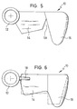
- Fig. 5 shows a variant of the stirring element according to Fig. 1, in which a slot 58 is formed between the main blade 14 and the side blade 16, i.e. the two stirring blades are connected to one another only over part of the tangential width of the main blade 14.
- FIG. 6 also shows a variant of the stirring element 10, in which the main blade 14 is only fastened to the spar 18 (but not directly to the hub 12) and the edges of the main blade 14 are rounded and the transition between the main blade 14 and the side blade 16 is rounded.
- a broken line variant of an angular design variant of an outer contour of a stirring element with main blade and side blade is shown as an example in broken line in FIG. 6.
- the same or similar variants can accordingly also be provided in the other embodiments of the stirring elements shown, as well as combinations of partially rounded and partially angular.
- the stirring element according to the invention can be designed with multiple blades, in particular with two blades.
- the ratio of the outside diameter of the stirring element to the inside diameter of the stirring container is about 0.2 to about 0.7.
- the conveyance is preferably carried out in the axial direction, with short-circuit currents being largely suppressed by the stirring element according to the invention, which results in a widened axial profile on the pressure side and is expressed by a significantly increased efficiency.
- the stirring element is preferably used for low-viscosity and medium-viscosity single- or multi-phase liquids in round or rectangular containers, which can have diameters of about 0.5 m to about 20 m and more. If necessary, several stirring elements can also be arranged one above the other on a stirrer shaft.
- a strongly focused axial jet can be generated in the stirred liquid, preferably in the direction of the container bottom. which ensures intensive mixing of the container contents.
- the stirring element according to the invention can consist of any metallic material or plastic. It can be surface treated, e.g. sandblasted, polished, clothed, coated, rubberized or enamelled. It can be used with or without a baffle in the stirred tank, and it can be installed centrically, eccentrically or at an angle in the stirred tank.
- the invention provides a stirrer for stirring e.g. low-viscosity and medium-viscosity liquids.
- the stirrer comprises an inner main blade and an outer side blade, both of which are connected to one another.
- the main blade is preferably bent down or arched in relation to the stirrer plane, while the side blade is preferably bent up or curved in relation to the stirrer plane.
- This design of the stirring element achieves a high hydraulic efficiency and thus enables very good mixing of the material to be mixed with the lowest possible energy inputs.
Landscapes
- Engineering & Computer Science (AREA)
- Aviation & Aerospace Engineering (AREA)
- Chemical & Material Sciences (AREA)
- Chemical Kinetics & Catalysis (AREA)
- Mixers Of The Rotary Stirring Type (AREA)
- Accessories For Mixers (AREA)
Applications Claiming Priority (2)
| Application Number | Priority Date | Filing Date | Title |
|---|---|---|---|
| DE4401596A DE4401596A1 (de) | 1994-01-20 | 1994-01-20 | Rührorgan |
| DE4401596 | 1994-01-20 |
Publications (2)
| Publication Number | Publication Date |
|---|---|
| EP0664155A1 true EP0664155A1 (fr) | 1995-07-26 |
| EP0664155B1 EP0664155B1 (fr) | 1998-06-10 |
Family
ID=6508325
Family Applications (1)
| Application Number | Title | Priority Date | Filing Date |
|---|---|---|---|
| EP95100723A Expired - Lifetime EP0664155B1 (fr) | 1994-01-20 | 1995-01-19 | Agitateur |
Country Status (6)
| Country | Link |
|---|---|
| US (1) | US5595475A (fr) |
| EP (1) | EP0664155B1 (fr) |
| JP (1) | JPH07308559A (fr) |
| DE (2) | DE4401596A1 (fr) |
| NO (1) | NO950198L (fr) |
| RU (1) | RU95100778A (fr) |
Cited By (2)
| Publication number | Priority date | Publication date | Assignee | Title |
|---|---|---|---|---|
| WO2017097530A1 (fr) * | 2015-12-10 | 2017-06-15 | EKATO Rühr- und Mischtechnik GmbH | Dispositif de mélange |
| WO2018029332A3 (fr) * | 2016-08-12 | 2018-04-19 | EKATO Rühr- und Mischtechnik GmbH | Dispositif agitateur et procédé |
Families Citing this family (14)
| Publication number | Priority date | Publication date | Assignee | Title |
|---|---|---|---|---|
| DE19709818B4 (de) * | 1997-03-10 | 2007-09-27 | Wilo Ag | Tauchrührwerk |
| DE19720120C2 (de) * | 1997-05-14 | 2001-03-01 | Hoesch & Soehne Eberhard | Rührorgan |
| US6334705B1 (en) | 1998-10-01 | 2002-01-01 | General Signal Corporation | Fluid mixing impellers with shear generating venturi |
| US6634784B2 (en) * | 2001-08-17 | 2003-10-21 | Spx Corporation | Mixing impeller device and method |
| DE10321350B4 (de) * | 2003-05-13 | 2005-04-21 | Lurgi Ag | Mischvorrichtung |
| US20050281676A1 (en) * | 2004-06-16 | 2005-12-22 | Egolf Thomas A | Multi-hedral rotary wing |
| US7246998B2 (en) * | 2004-11-18 | 2007-07-24 | Sikorsky Aircraft Corporation | Mission replaceable rotor blade tip section |
| DE202006007423U1 (de) * | 2006-05-09 | 2007-09-13 | EKATO Rühr- und Mischtechnik GmbH | Rührorgan |
| DE102007008131A1 (de) * | 2007-02-19 | 2008-08-21 | Invent Umwelt-Und Verfahrenstechnik Ag | Horizontalrührwerk zum Erzeugen einer Strömung in einem Klärbecken |
| FI123826B (en) * | 2012-02-20 | 2013-11-15 | Outotec Oyj | Axial flow propeller blade and axial flow propeller |
| US9248420B2 (en) | 2013-12-16 | 2016-02-02 | Pall Corporation | High turndown impeller |
| EP2926892B1 (fr) * | 2014-04-04 | 2021-01-13 | Milton Roy Europe | Mobile d'agitation |
| DE102014110542A1 (de) * | 2014-07-25 | 2016-01-28 | EKATO Rühr- und Mischtechnik GmbH | Rührorganvorrichtung |
| KR102408877B1 (ko) | 2014-08-13 | 2022-06-13 | 베르살리스 에스.피.에이. | 회전자 및 교반 디바이스 |
Citations (5)
| Publication number | Priority date | Publication date | Assignee | Title |
|---|---|---|---|---|
| US2193686A (en) * | 1938-10-24 | 1940-03-12 | Frederick L Craddock | Mixing apparatus |
| FR1600744A (fr) * | 1968-12-11 | 1970-07-27 | ||
| DE8700251U1 (de) * | 1986-01-16 | 1987-06-11 | N.V. Philips' Gloeilampenfabrieken, Eindhoven | Mischwerkzeug für eine Speiseeismaschine |
| EP0542713A1 (fr) * | 1991-11-12 | 1993-05-19 | A. Ahlstrom Corporation | Procédé et dispositif pour mélanger des fluides |
| EP0577456A1 (fr) * | 1992-06-30 | 1994-01-05 | Pierre Guerin S.A. | Agitateur rotatif à hélice |
Family Cites Families (6)
| Publication number | Priority date | Publication date | Assignee | Title |
|---|---|---|---|---|
| DE1503704C3 (de) * | 1966-12-30 | 1972-03-23 | Arthur Pfeiffer Hochvakuumtechnik Gmbh, 6330 Wetzlar | Schaufelkranz fuer ein lauf und oder leitrad einer turbomolekularpumpe |
| US4142837A (en) * | 1977-11-11 | 1979-03-06 | United Technologies Corporation | Helicopter blade |
| GB9022281D0 (en) * | 1990-10-13 | 1991-02-20 | Westland Helicopters | Helicopter rotor blades |
| GB9023141D0 (en) * | 1990-10-24 | 1991-07-10 | Westland Helicopters | Helicopter rotor blades |
| GB9112835D0 (en) * | 1991-06-14 | 1992-05-27 | Westland Helicopters | Helicopter rotor blades |
| US5320494A (en) * | 1992-12-22 | 1994-06-14 | United Technologies Corporation | Helicopter rotor blade having a replaceable anhedral tip |
-
1994
- 1994-01-20 DE DE4401596A patent/DE4401596A1/de not_active Withdrawn
-
1995
- 1995-01-19 NO NO950198A patent/NO950198L/no unknown
- 1995-01-19 EP EP95100723A patent/EP0664155B1/fr not_active Expired - Lifetime
- 1995-01-19 DE DE59502445T patent/DE59502445D1/de not_active Expired - Fee Related
- 1995-01-20 US US08/375,956 patent/US5595475A/en not_active Expired - Lifetime
- 1995-01-20 JP JP7007733A patent/JPH07308559A/ja active Pending
- 1995-01-20 RU RU95100778/25A patent/RU95100778A/ru unknown
Patent Citations (5)
| Publication number | Priority date | Publication date | Assignee | Title |
|---|---|---|---|---|
| US2193686A (en) * | 1938-10-24 | 1940-03-12 | Frederick L Craddock | Mixing apparatus |
| FR1600744A (fr) * | 1968-12-11 | 1970-07-27 | ||
| DE8700251U1 (de) * | 1986-01-16 | 1987-06-11 | N.V. Philips' Gloeilampenfabrieken, Eindhoven | Mischwerkzeug für eine Speiseeismaschine |
| EP0542713A1 (fr) * | 1991-11-12 | 1993-05-19 | A. Ahlstrom Corporation | Procédé et dispositif pour mélanger des fluides |
| EP0577456A1 (fr) * | 1992-06-30 | 1994-01-05 | Pierre Guerin S.A. | Agitateur rotatif à hélice |
Cited By (9)
| Publication number | Priority date | Publication date | Assignee | Title |
|---|---|---|---|---|
| WO2017097530A1 (fr) * | 2015-12-10 | 2017-06-15 | EKATO Rühr- und Mischtechnik GmbH | Dispositif de mélange |
| CN109070028A (zh) * | 2015-12-10 | 2018-12-21 | 艾卡多搅拌及混合工程有限公司 | 搅拌装置 |
| RU2729276C2 (ru) * | 2015-12-10 | 2020-08-05 | Экато Рюр-Унд Миштехник Гмбх | Устройство для перемешивания |
| TWI721053B (zh) * | 2015-12-10 | 2021-03-11 | 德商艾卡多攪拌及混合工程有限公司 | 攪拌設備、混合器及生產產物之方法 |
| US11059006B2 (en) | 2015-12-10 | 2021-07-13 | EKATO Rühr- und Mischtechnik GmbH | Agitator device |
| CN109070028B (zh) * | 2015-12-10 | 2021-12-24 | 艾卡多搅拌及混合工程有限公司 | 搅拌装置 |
| WO2018029332A3 (fr) * | 2016-08-12 | 2018-04-19 | EKATO Rühr- und Mischtechnik GmbH | Dispositif agitateur et procédé |
| CN109715278A (zh) * | 2016-08-12 | 2019-05-03 | 艾卡多搅拌及混合工程有限公司 | 搅拌装置和方法 |
| US11420166B2 (en) | 2016-08-12 | 2022-08-23 | EKATO Rühr- und Mischtechnik GmbH | Agitator device and method |
Also Published As
| Publication number | Publication date |
|---|---|
| JPH07308559A (ja) | 1995-11-28 |
| NO950198D0 (no) | 1995-01-19 |
| US5595475A (en) | 1997-01-21 |
| DE4401596A1 (de) | 1995-07-27 |
| EP0664155B1 (fr) | 1998-06-10 |
| RU95100778A (ru) | 1996-10-27 |
| NO950198L (no) | 1995-07-21 |
| DE59502445D1 (de) | 1998-07-16 |
Similar Documents
| Publication | Publication Date | Title |
|---|---|---|
| EP0664155A1 (fr) | Agitateur | |
| DE69108621T2 (de) | Mischerlaufrad mit hohem wirkungsgrad. | |
| EP3171970B1 (fr) | Dispositif d'organe d'agitation | |
| EP0546989B1 (fr) | Elément de mélange statique avec surfaces de guidage | |
| EP1631371A1 (fr) | Dispositif pour le traitement de solides | |
| DE69802823T2 (de) | Wischblatt mit einem windleitelement | |
| DE2557979C2 (de) | Interferenzstrom-Rührvorrichtung | |
| DE2160410A1 (de) | Mischvorrichtung | |
| DE2439683C2 (fr) | ||
| DE2643560C2 (de) | Rührvorrichtung | |
| DE102017101680A1 (de) | Hydrofoil für ein Wasserfahrzeug | |
| EP2321398B9 (fr) | Cuve à maische pour la fabrication de bière et malaxeur pour cuve à maische | |
| EP3409575A1 (fr) | Safran comprenant un moyeu et moyeu de safran | |
| DE202017103233U1 (de) | Ruderblatt mit einer Ruderblattnabe und Ruderblattnabe für ein Ruderblatt | |
| DE3404233A1 (de) | Zerkleinerungs- und ruehrvorrichtung fuer lebensmittel | |
| DE3730423A1 (de) | Ruehrvorrichtung | |
| DE9400938U1 (de) | Rührorgan | |
| DE2525362C3 (de) | Mischflügel an einem rotierenden Mischwerkzeug | |
| EP0266802B1 (fr) | Hélice carenée | |
| DE112013002676T5 (de) | Rotorelement und Rotor für eine Siebvorrichtung | |
| DE2314241B2 (de) | Zellenloses Schaufelrad mit einem Tragkörper | |
| DE4117773A1 (de) | Ruehrvorrichtung | |
| DE3340750C2 (fr) | ||
| DE102010046121A1 (de) | Rührblatt und Rührvorrichtung | |
| DE202015004925U1 (de) | Propeller |
Legal Events
| Date | Code | Title | Description |
|---|---|---|---|
| PUAI | Public reference made under article 153(3) epc to a published international application that has entered the european phase |
Free format text: ORIGINAL CODE: 0009012 |
|
| AK | Designated contracting states |
Kind code of ref document: A1 Designated state(s): CH DE FR GB IT LI NL |
|
| 17P | Request for examination filed |
Effective date: 19960126 |
|
| 17Q | First examination report despatched |
Effective date: 19961223 |
|
| GRAG | Despatch of communication of intention to grant |
Free format text: ORIGINAL CODE: EPIDOS AGRA |
|
| GRAG | Despatch of communication of intention to grant |
Free format text: ORIGINAL CODE: EPIDOS AGRA |
|
| GRAH | Despatch of communication of intention to grant a patent |
Free format text: ORIGINAL CODE: EPIDOS IGRA |
|
| GRAH | Despatch of communication of intention to grant a patent |
Free format text: ORIGINAL CODE: EPIDOS IGRA |
|
| GRAA | (expected) grant |
Free format text: ORIGINAL CODE: 0009210 |
|
| AK | Designated contracting states |
Kind code of ref document: B1 Designated state(s): CH DE FR GB IT LI NL |
|
| REG | Reference to a national code |
Ref country code: CH Ref legal event code: NV Representative=s name: PA ALDO ROEMPLER Ref country code: CH Ref legal event code: EP |
|
| ITF | It: translation for a ep patent filed | ||
| GBT | Gb: translation of ep patent filed (gb section 77(6)(a)/1977) |
Effective date: 19980611 |
|
| REF | Corresponds to: |
Ref document number: 59502445 Country of ref document: DE Date of ref document: 19980716 |
|
| ET | Fr: translation filed | ||
| PLBE | No opposition filed within time limit |
Free format text: ORIGINAL CODE: 0009261 |
|
| STAA | Information on the status of an ep patent application or granted ep patent |
Free format text: STATUS: NO OPPOSITION FILED WITHIN TIME LIMIT |
|
| 26N | No opposition filed | ||
| REG | Reference to a national code |
Ref country code: GB Ref legal event code: IF02 |
|
| PGFP | Annual fee paid to national office [announced via postgrant information from national office to epo] |
Ref country code: GB Payment date: 20050112 Year of fee payment: 11 |
|
| PGFP | Annual fee paid to national office [announced via postgrant information from national office to epo] |
Ref country code: NL Payment date: 20050118 Year of fee payment: 11 |
|
| PGFP | Annual fee paid to national office [announced via postgrant information from national office to epo] |
Ref country code: FR Payment date: 20050119 Year of fee payment: 11 |
|
| PGFP | Annual fee paid to national office [announced via postgrant information from national office to epo] |
Ref country code: CH Payment date: 20050125 Year of fee payment: 11 |
|
| PGFP | Annual fee paid to national office [announced via postgrant information from national office to epo] |
Ref country code: DE Payment date: 20050127 Year of fee payment: 11 |
|
| PG25 | Lapsed in a contracting state [announced via postgrant information from national office to epo] |
Ref country code: GB Free format text: LAPSE BECAUSE OF NON-PAYMENT OF DUE FEES Effective date: 20060119 |
|
| PG25 | Lapsed in a contracting state [announced via postgrant information from national office to epo] |
Ref country code: LI Free format text: LAPSE BECAUSE OF NON-PAYMENT OF DUE FEES Effective date: 20060131 Ref country code: FR Free format text: LAPSE BECAUSE OF NON-PAYMENT OF DUE FEES Effective date: 20060131 Ref country code: CH Free format text: LAPSE BECAUSE OF NON-PAYMENT OF DUE FEES Effective date: 20060131 |
|
| PGFP | Annual fee paid to national office [announced via postgrant information from national office to epo] |
Ref country code: IT Payment date: 20060131 Year of fee payment: 12 |
|
| PG25 | Lapsed in a contracting state [announced via postgrant information from national office to epo] |
Ref country code: NL Free format text: LAPSE BECAUSE OF NON-PAYMENT OF DUE FEES Effective date: 20060801 Ref country code: DE Free format text: LAPSE BECAUSE OF NON-PAYMENT OF DUE FEES Effective date: 20060801 |
|
| REG | Reference to a national code |
Ref country code: CH Ref legal event code: PL |
|
| GBPC | Gb: european patent ceased through non-payment of renewal fee |
Effective date: 20060119 |
|
| NLV4 | Nl: lapsed or anulled due to non-payment of the annual fee |
Effective date: 20060801 |
|
| REG | Reference to a national code |
Ref country code: FR Ref legal event code: ST Effective date: 20060929 |
|
| PG25 | Lapsed in a contracting state [announced via postgrant information from national office to epo] |
Ref country code: IT Free format text: LAPSE BECAUSE OF NON-PAYMENT OF DUE FEES Effective date: 20070119 |