EP0664227A1 - Roue - Google Patents
Roue Download PDFInfo
- Publication number
- EP0664227A1 EP0664227A1 EP95100873A EP95100873A EP0664227A1 EP 0664227 A1 EP0664227 A1 EP 0664227A1 EP 95100873 A EP95100873 A EP 95100873A EP 95100873 A EP95100873 A EP 95100873A EP 0664227 A1 EP0664227 A1 EP 0664227A1
- Authority
- EP
- European Patent Office
- Prior art keywords
- disc
- lug
- rim
- wheel
- bolts
- Prior art date
- Legal status (The legal status is an assumption and is not a legal conclusion. Google has not performed a legal analysis and makes no representation as to the accuracy of the status listed.)
- Granted
Links
- 238000003466 welding Methods 0.000 claims abstract description 7
- 230000001788 irregular Effects 0.000 claims abstract description 3
- 238000010276 construction Methods 0.000 description 4
- 238000000034 method Methods 0.000 description 2
- 239000003973 paint Substances 0.000 description 2
- 230000015572 biosynthetic process Effects 0.000 description 1
- 230000006835 compression Effects 0.000 description 1
- 238000007906 compression Methods 0.000 description 1
- 238000004519 manufacturing process Methods 0.000 description 1
- 230000013011 mating Effects 0.000 description 1
- 238000010422 painting Methods 0.000 description 1
Images
Classifications
-
- B—PERFORMING OPERATIONS; TRANSPORTING
- B60—VEHICLES IN GENERAL
- B60B—VEHICLE WHEELS; CASTORS; AXLES FOR WHEELS OR CASTORS; INCREASING WHEEL ADHESION
- B60B23/00—Attaching rim to wheel body
- B60B23/12—Attaching rim to wheel body by devices arranged to permit variation of axial position of rim relative to wheel body for track width adjustment
Definitions
- This invention relates to a manually adjustable wheel of the type frequently utilised on agricultural tractors.
- Such known manually adjustable wheels usually comprise a rim detachably secured to a disc which is itself detachably secured in conventional manner to a rotary member such as a driveshaft.
- the means for detachably securing the rim to the disc usually comprises a plurality of lugs spaced apart circumferentially around the radially inner surface of the rim.
- British patent specification GB-A-2 058 686 discloses differing embodiments of manually adjustable wheels for agricultural tractors wherein the wheel disc is formed from a square blank to a generally octagonal shape having four longer sides which alternate around the periphery of the disc with four shorter sides. Each of the shorter sides of the disc is secured by a pair of circumferentially spaced apart lugs to the wheel rim, the lugs themselves being welded to the radially inner surface of the rim.
- the lugs are all of generally top hat section providing a bolt-receiving channel extending axially of the rim with circumferentially extending feet of each lug being welded to the radially inner surface of the rim.
- a further embodiment disclosed in this specification discloses all of the lugs again being of generally top hat section but being welded to the radially inner surface of the rim so that the channel of each lug extends perpendicular to the rotary axis of the wheel.
- the disc is secured to each lug by means of a bolt extending through the opposed side walls of the lug.
- it is known to strengthen the lugs by providing a strut such as in the form of a tube extending between the opposed inner surfaces of the side walls of each lug whereby when the bolt is tightened to secure the disc to the rim the struts are placed in compression.
- each of the lugs is of generally top hat form providing a channel section which extends generally perpendicular to the rotary axis of the wheel.
- Each of the lugs has axially outwardly extending feet whereby the axially outer edges of such feet are securable to the wheel rim by fillet welding to the radially inner surface thereof.
- each lug is reinforced against axial compressive forces by providing the wheel rim with a special mating profile comprising a cylindrical portion displaced radially inwardly of the rim well. Said radially inwardly displaced portion is formed with an axial dimension so as to enable it to fit snugly within the axial confines of each lug.
- axial compressive forces imparted to the lug when the disc is secured thereto by bolting are resisted by said radially inwardly displaced part of the wheel rim acting as a strut.
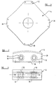
- a manually adjustable wheel for a vehicle e.g. an agricultural tractor comprising a rim to receive a tyre, the rim having at least one cylindrical portion; a plurality of channel-shaped lugs spaced apart around the radially inner surface of a said cylindrical portion of the rim, the channel in each lug extending perpendicular to the rotary axis of the wheel and receiving a pair of circumferentially spaced apart bolts extending transversely across said channel and through the walls thereof, each lug having flanges extending circumferentially of the wheel rim and being attached by welding to said radially inner surface of a said cylindrical portion of the rim; and a wheel disc for connection to a hub of the vehicle, the disc having substantially the shape of a square with the corners removed to provide an irregular generally octagonal shape having four longer sides and four shorter sides arranged alternately around the periphery of the octagon each shorter side being juxtaposed against a said lug,
- each said lug is provided with axially outwardly extending bosses whereby when a said lug is juxtaposed to a said shorter side of the disc the said bosses are in contact with said disc and a space is defined between the disc and the remainder of the wall of the lug.
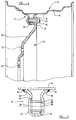
- a wheel in accordance with the invention comprises a wheel rim 10 having four circumferentially spaced apart lugs 12 secured to the radially inner surface thereof, each of the lugs being secured to a wheel disc 14 by means of two bolts extending axially through each lug.
- the wheel rim 10 may be of generally conventional construction comprising either a single well configuration or, as illustrated, a double well configuration wherein two cylindrical portions 16 and 18 of the wheel rim are provided radially displaced from one another.
- the disc 14 has a central planar portion or nave 20 securable in known manner by bolting to a driveshaft of a tractor. Radially outwardly of the nave 20 there is provided a further planar portion 22 perpendicular to the rotary axis of the wheel but axially displaced therefrom. Radially outwardly of this portion 22 there is a conical portion 24 and radially outwardly of that there is a rim portion 26 perpendicular to the rotary axis of the wheel. Each of such rim portions provides a shorter side of the generally octagonal disc 14.
- Each of the lugs 12 is of generally channel-shaped top hat cross-section having generally parallel opposed planar side walls 28 extending circumferentially of the rim and having axially outwardly directed feet 30 securable to one of the cylindrical well portions 16 or 18 of the rim. As illustrated, each of the opposed side walls 28 of each lug is formed with an axially outwardly displaced boss portion 32. Internally of each lug there is provided a strut typically in the form of a tube 34 which is locatable within the lug during formation thereof by means of opposed recesses provided by the axially outwardly displaced boss portions 32.
- Each lug 12 is secured to a said well portion 16 of the wheel rim as illustrated by circumferentially extending fillet welding 34 along the axially outer edges of the lug feet 30. If desired, fillet welding may also be provided to extend axially around the corner of each end of each lug foot 30.
- Each shorter side 26 of the wheel disc is secured to a respective lug by bolts 36 which have squared portions on their shanks to engage in square section holes 38 in the walls 28 of a said lug, each bolt having a threaded portion to receive a nut 40 and washer 42.
- variation in track of a vehicle having wheels constructed in accordance with the invention is obtained either by reversing the disc and/or by arranging the disc to be secured at one side or the other of the lugs.
- the planar rim portion of the disc comprising a short side 26 thereof abuts tightly against the axially extending bosses 32 on the respective side wall 28 of each lug thereby affording a small axial clearance between the remainder of the side wall and the adjacent surface of the disc rim portion 26.
- This axial clearance permits ingress of paint during the painting operation whereby the assembled disc and rim may be painted as a unit rather than having to paint them separately and then assemble them after having been painted.
- the lugs of a wheel constructed in accordance with the invention are sufficiently strong to accommodate the compressive forces imparted thereto when the wheel disc is bolted to the lugs. Thus there is no need to provide a special rim section to reinforce the lug. Hence, during manufacture, the lugs may be welded to the wheel rim at either of the two cylindrical rim portions 16 or 18 of a double well rim.
Landscapes
- Engineering & Computer Science (AREA)
- Mechanical Engineering (AREA)
- Tires In General (AREA)
- Pulleys (AREA)
- Agricultural Machines (AREA)
- Turbine Rotor Nozzle Sealing (AREA)
- Microscoopes, Condenser (AREA)
Applications Claiming Priority (2)
| Application Number | Priority Date | Filing Date | Title |
|---|---|---|---|
| GB9401314 | 1994-01-25 | ||
| GB9401314A GB2285957B (en) | 1994-01-25 | 1994-01-25 | Wheel |
Publications (2)
| Publication Number | Publication Date |
|---|---|
| EP0664227A1 true EP0664227A1 (fr) | 1995-07-26 |
| EP0664227B1 EP0664227B1 (fr) | 1998-03-18 |
Family
ID=10749227
Family Applications (1)
| Application Number | Title | Priority Date | Filing Date |
|---|---|---|---|
| EP95100873A Expired - Lifetime EP0664227B1 (fr) | 1994-01-25 | 1995-01-23 | Roue |
Country Status (8)
| Country | Link |
|---|---|
| US (1) | US5560686A (fr) |
| EP (1) | EP0664227B1 (fr) |
| AT (1) | ATE164124T1 (fr) |
| DE (1) | DE69501793T2 (fr) |
| DK (1) | DK0664227T3 (fr) |
| ES (1) | ES2113686T3 (fr) |
| GB (1) | GB2285957B (fr) |
| GR (1) | GR3026406T3 (fr) |
Cited By (2)
| Publication number | Priority date | Publication date | Assignee | Title |
|---|---|---|---|---|
| EP0911183A3 (fr) * | 1997-10-14 | 2001-10-04 | Titan International Inc. | Roue |
| EP1186442A3 (fr) * | 2000-09-06 | 2003-10-01 | TITAN ITALIA S.p.A. | Roue pour voie à écartement variable avec système de centrage à chevilles |
Families Citing this family (7)
| Publication number | Priority date | Publication date | Assignee | Title |
|---|---|---|---|---|
| GB9410516D0 (en) * | 1994-05-25 | 1994-07-13 | Gkn Sankey Ltd | A welded assembly and method for its production |
| GB2336813B (en) * | 1998-04-30 | 2002-04-03 | Gkn Sankey Ltd | Method of making a wheel |
| GB2341152A (en) * | 1998-09-04 | 2000-03-08 | Gkn Sankey Ltd | Making vehicle wheels |
| GB2431141B (en) | 2005-10-12 | 2009-07-29 | Gkn Offhighway Systems Ltd | Wheel construction |
| ATE537012T1 (de) | 2008-04-04 | 2011-12-15 | Gkn Land Systems Ltd | Radaufbau |
| EP2193931B1 (fr) | 2008-12-02 | 2011-08-17 | GKN Land Systems Limited | Construction de roue |
| DK2607097T3 (en) * | 2011-12-20 | 2016-01-25 | Titan Italia S P A | Wheels with variable track |
Citations (5)
| Publication number | Priority date | Publication date | Assignee | Title |
|---|---|---|---|---|
| GB2058686A (en) * | 1979-09-18 | 1981-04-15 | Gkn Sankey Ltd | Variable-track wheels |
| GB2167717A (en) * | 1984-12-01 | 1986-06-04 | Gkn Sankey Ltd | Adjustable track width tractor wheel |
| GB2168014A (en) * | 1984-12-01 | 1986-06-11 | Gkn Sankey Ltd | Power adjusted variable track wheel |
| EP0405100A1 (fr) * | 1989-06-28 | 1991-01-02 | LEMMERZ-WERKE KGaA | Roue à écartement réglable |
| FR2686549A3 (en) * | 1992-01-24 | 1993-07-30 | Sirmac Officine Meccaniche Spa | Wheel with fixing flanges with two bolts with variable track for vehicles |
Family Cites Families (4)
| Publication number | Priority date | Publication date | Assignee | Title |
|---|---|---|---|---|
| US2384649A (en) * | 1941-12-19 | 1945-09-11 | Kelsey Hayes Wheel Co | Wheel |
| GB626840A (en) * | 1947-09-06 | 1949-07-21 | Dunlop Rubber Co | Improvements in wheel rims for tractors and like vehicles |
| US3788705A (en) * | 1972-03-15 | 1974-01-29 | J Brainard | Vehicle wheel and spider therefor |
| DE3821533A1 (de) * | 1988-06-25 | 1989-12-28 | Lemmerz Werke Kgaa | Haltebock fuer spurverstellraeder |
-
1994
- 1994-01-25 GB GB9401314A patent/GB2285957B/en not_active Expired - Fee Related
-
1995
- 1995-01-23 DE DE69501793T patent/DE69501793T2/de not_active Expired - Fee Related
- 1995-01-23 AT AT95100873T patent/ATE164124T1/de not_active IP Right Cessation
- 1995-01-23 EP EP95100873A patent/EP0664227B1/fr not_active Expired - Lifetime
- 1995-01-23 DK DK95100873.9T patent/DK0664227T3/da active
- 1995-01-23 ES ES95100873T patent/ES2113686T3/es not_active Expired - Lifetime
- 1995-01-24 US US08/377,255 patent/US5560686A/en not_active Expired - Lifetime
-
1998
- 1998-03-19 GR GR980400479T patent/GR3026406T3/el unknown
Patent Citations (5)
| Publication number | Priority date | Publication date | Assignee | Title |
|---|---|---|---|---|
| GB2058686A (en) * | 1979-09-18 | 1981-04-15 | Gkn Sankey Ltd | Variable-track wheels |
| GB2167717A (en) * | 1984-12-01 | 1986-06-04 | Gkn Sankey Ltd | Adjustable track width tractor wheel |
| GB2168014A (en) * | 1984-12-01 | 1986-06-11 | Gkn Sankey Ltd | Power adjusted variable track wheel |
| EP0405100A1 (fr) * | 1989-06-28 | 1991-01-02 | LEMMERZ-WERKE KGaA | Roue à écartement réglable |
| FR2686549A3 (en) * | 1992-01-24 | 1993-07-30 | Sirmac Officine Meccaniche Spa | Wheel with fixing flanges with two bolts with variable track for vehicles |
Cited By (2)
| Publication number | Priority date | Publication date | Assignee | Title |
|---|---|---|---|---|
| EP0911183A3 (fr) * | 1997-10-14 | 2001-10-04 | Titan International Inc. | Roue |
| EP1186442A3 (fr) * | 2000-09-06 | 2003-10-01 | TITAN ITALIA S.p.A. | Roue pour voie à écartement variable avec système de centrage à chevilles |
Also Published As
| Publication number | Publication date |
|---|---|
| ATE164124T1 (de) | 1998-04-15 |
| EP0664227B1 (fr) | 1998-03-18 |
| GB9401314D0 (en) | 1994-03-23 |
| DE69501793T2 (de) | 1998-07-09 |
| GB2285957A (en) | 1995-08-02 |
| DE69501793D1 (de) | 1998-04-23 |
| GR3026406T3 (en) | 1998-06-30 |
| GB2285957B (en) | 1997-10-15 |
| US5560686A (en) | 1996-10-01 |
| DK0664227T3 (da) | 1998-04-14 |
| ES2113686T3 (es) | 1998-05-01 |
Similar Documents
| Publication | Publication Date | Title |
|---|---|---|
| US5358313A (en) | Adjustable wheel liner for trucks | |
| KR100578458B1 (ko) | 휠 지지 조립체 및 그 방법 | |
| US5000241A (en) | Unitary bead-lock and run-flat roller support ring for pneumatic tires on two-part wheels | |
| EP0664227B1 (fr) | Roue | |
| US6629736B2 (en) | Fabricated vehicle wheel | |
| US6626503B2 (en) | Fabricated vehicle wheel | |
| EP0025677B1 (fr) | Roues réglables manuellement pour voie à écartement variable | |
| US4643484A (en) | Manually adjustable wheels | |
| EP1934061A1 (fr) | Construction de roue | |
| CA1145379A (fr) | Roues reglables a la main | |
| CA1327221C (fr) | Roue porteuse ajustable | |
| US20170036482A1 (en) | Tireless Skid Steer Wheels | |
| US4883324A (en) | Support block for track adjustment wheels | |
| GB2167717A (en) | Adjustable track width tractor wheel | |
| US6655748B2 (en) | Fabricated vehicle wheel | |
| US6370777B1 (en) | Method for producing a full face vehicle wheel | |
| US2890911A (en) | Pressed steel truck wheel | |
| DE3048062C2 (de) | Felgenanordnung | |
| US6179388B1 (en) | Method of making a wheel | |
| EP0684104B1 (fr) | Procédé pour la production d'un ensemble soudé | |
| US2304945A (en) | Steering wheel insert | |
| KR20040027877A (ko) | 휠지지 조립체와 허브 | |
| US2660477A (en) | Pressed steel truck wheel | |
| US2065275A (en) | Metal wheel and method of making the same | |
| KR20210022545A (ko) | 경량화 포켓들을 갖는 휠 디스크를 구비한 조립형 차량용 휠 |
Legal Events
| Date | Code | Title | Description |
|---|---|---|---|
| PUAI | Public reference made under article 153(3) epc to a published international application that has entered the european phase |
Free format text: ORIGINAL CODE: 0009012 |
|
| AK | Designated contracting states |
Kind code of ref document: A1 Designated state(s): AT BE CH DE DK ES FR GR IT LI NL PT SE |
|
| 17P | Request for examination filed |
Effective date: 19960108 |
|
| 17Q | First examination report despatched |
Effective date: 19961021 |
|
| GRAG | Despatch of communication of intention to grant |
Free format text: ORIGINAL CODE: EPIDOS AGRA |
|
| GRAG | Despatch of communication of intention to grant |
Free format text: ORIGINAL CODE: EPIDOS AGRA |
|
| GRAH | Despatch of communication of intention to grant a patent |
Free format text: ORIGINAL CODE: EPIDOS IGRA |
|
| GRAH | Despatch of communication of intention to grant a patent |
Free format text: ORIGINAL CODE: EPIDOS IGRA |
|
| GRAA | (expected) grant |
Free format text: ORIGINAL CODE: 0009210 |
|
| AK | Designated contracting states |
Kind code of ref document: B1 Designated state(s): AT BE CH DE DK ES FR GR IT LI NL PT SE |
|
| REF | Corresponds to: |
Ref document number: 164124 Country of ref document: AT Date of ref document: 19980415 Kind code of ref document: T |
|
| ITF | It: translation for a ep patent filed | ||
| REG | Reference to a national code |
Ref country code: CH Ref legal event code: NV Representative=s name: ISLER & PEDRAZZINI AG Ref country code: CH Ref legal event code: EP |
|
| REG | Reference to a national code |
Ref country code: DK Ref legal event code: T3 |
|
| REF | Corresponds to: |
Ref document number: 69501793 Country of ref document: DE Date of ref document: 19980423 |
|
| ET | Fr: translation filed | ||
| REG | Reference to a national code |
Ref country code: ES Ref legal event code: FG2A Ref document number: 2113686 Country of ref document: ES Kind code of ref document: T3 |
|
| REG | Reference to a national code |
Ref country code: PT Ref legal event code: SC4A Free format text: AVAILABILITY OF NATIONAL TRANSLATION Effective date: 19980323 |
|
| PLBE | No opposition filed within time limit |
Free format text: ORIGINAL CODE: 0009261 |
|
| STAA | Information on the status of an ep patent application or granted ep patent |
Free format text: STATUS: NO OPPOSITION FILED WITHIN TIME LIMIT |
|
| 26N | No opposition filed | ||
| PGFP | Annual fee paid to national office [announced via postgrant information from national office to epo] |
Ref country code: PT Payment date: 20010104 Year of fee payment: 7 |
|
| PGFP | Annual fee paid to national office [announced via postgrant information from national office to epo] |
Ref country code: SE Payment date: 20010105 Year of fee payment: 7 |
|
| PGFP | Annual fee paid to national office [announced via postgrant information from national office to epo] |
Ref country code: DE Payment date: 20010115 Year of fee payment: 7 |
|
| PGFP | Annual fee paid to national office [announced via postgrant information from national office to epo] |
Ref country code: DK Payment date: 20010116 Year of fee payment: 7 Ref country code: AT Payment date: 20010116 Year of fee payment: 7 |
|
| PGFP | Annual fee paid to national office [announced via postgrant information from national office to epo] |
Ref country code: ES Payment date: 20010122 Year of fee payment: 7 |
|
| PGFP | Annual fee paid to national office [announced via postgrant information from national office to epo] |
Ref country code: FR Payment date: 20010125 Year of fee payment: 7 |
|
| PGFP | Annual fee paid to national office [announced via postgrant information from national office to epo] |
Ref country code: GR Payment date: 20010129 Year of fee payment: 7 |
|
| PGFP | Annual fee paid to national office [announced via postgrant information from national office to epo] |
Ref country code: NL Payment date: 20010131 Year of fee payment: 7 |
|
| PGFP | Annual fee paid to national office [announced via postgrant information from national office to epo] |
Ref country code: CH Payment date: 20010219 Year of fee payment: 7 |
|
| PGFP | Annual fee paid to national office [announced via postgrant information from national office to epo] |
Ref country code: BE Payment date: 20010313 Year of fee payment: 7 |
|
| PG25 | Lapsed in a contracting state [announced via postgrant information from national office to epo] |
Ref country code: DK Free format text: LAPSE BECAUSE OF NON-PAYMENT OF DUE FEES Effective date: 20020123 Ref country code: AT Free format text: LAPSE BECAUSE OF NON-PAYMENT OF DUE FEES Effective date: 20020123 |
|
| PG25 | Lapsed in a contracting state [announced via postgrant information from national office to epo] |
Ref country code: SE Free format text: LAPSE BECAUSE OF NON-PAYMENT OF DUE FEES Effective date: 20020124 Ref country code: ES Free format text: LAPSE BECAUSE OF NON-PAYMENT OF DUE FEES Effective date: 20020124 |
|
| PG25 | Lapsed in a contracting state [announced via postgrant information from national office to epo] |
Ref country code: LI Free format text: LAPSE BECAUSE OF NON-PAYMENT OF DUE FEES Effective date: 20020131 Ref country code: CH Free format text: LAPSE BECAUSE OF NON-PAYMENT OF DUE FEES Effective date: 20020131 Ref country code: BE Free format text: LAPSE BECAUSE OF NON-PAYMENT OF DUE FEES Effective date: 20020131 |
|
| BERE | Be: lapsed |
Owner name: GKN SANKEY LTD Effective date: 20020131 |
|
| PG25 | Lapsed in a contracting state [announced via postgrant information from national office to epo] |
Ref country code: PT Free format text: LAPSE BECAUSE OF NON-PAYMENT OF DUE FEES Effective date: 20020731 |
|
| PG25 | Lapsed in a contracting state [announced via postgrant information from national office to epo] |
Ref country code: NL Free format text: LAPSE BECAUSE OF NON-PAYMENT OF DUE FEES Effective date: 20020801 Ref country code: DE Free format text: LAPSE BECAUSE OF NON-PAYMENT OF DUE FEES Effective date: 20020801 |
|
| PG25 | Lapsed in a contracting state [announced via postgrant information from national office to epo] |
Ref country code: GR Free format text: LAPSE BECAUSE OF NON-PAYMENT OF DUE FEES Effective date: 20020812 |
|
| EUG | Se: european patent has lapsed |
Ref document number: 95100873.9 |
|
| REG | Reference to a national code |
Ref country code: CH Ref legal event code: PL |
|
| PG25 | Lapsed in a contracting state [announced via postgrant information from national office to epo] |
Ref country code: FR Free format text: LAPSE BECAUSE OF NON-PAYMENT OF DUE FEES Effective date: 20020930 |
|
| NLV4 | Nl: lapsed or anulled due to non-payment of the annual fee |
Effective date: 20020801 |
|
| REG | Reference to a national code |
Ref country code: FR Ref legal event code: ST Ref country code: PT Ref legal event code: MM4A Free format text: LAPSE DUE TO NON-PAYMENT OF FEES Effective date: 20020731 |
|
| REG | Reference to a national code |
Ref country code: DK Ref legal event code: EBP |
|
| PG25 | Lapsed in a contracting state [announced via postgrant information from national office to epo] |
Ref country code: IT Free format text: LAPSE BECAUSE OF NON-PAYMENT OF DUE FEES;WARNING: LAPSES OF ITALIAN PATENTS WITH EFFECTIVE DATE BEFORE 2007 MAY HAVE OCCURRED AT ANY TIME BEFORE 2007. THE CORRECT EFFECTIVE DATE MAY BE DIFFERENT FROM THE ONE RECORDED. Effective date: 20050123 |