EP0664251B1 - Spoiler für ein Fahrzeug - Google Patents
Spoiler für ein Fahrzeug Download PDFInfo
- Publication number
- EP0664251B1 EP0664251B1 EP94203698A EP94203698A EP0664251B1 EP 0664251 B1 EP0664251 B1 EP 0664251B1 EP 94203698 A EP94203698 A EP 94203698A EP 94203698 A EP94203698 A EP 94203698A EP 0664251 B1 EP0664251 B1 EP 0664251B1
- Authority
- EP
- European Patent Office
- Prior art keywords
- air dam
- body portion
- bumper
- vehicle
- barbs
- Prior art date
- Legal status (The legal status is an assumption and is not a legal conclusion. Google has not performed a legal analysis and makes no representation as to the accuracy of the status listed.)
- Expired - Lifetime
Links
- 239000000463 material Substances 0.000 claims description 6
- 229920003023 plastic Polymers 0.000 claims description 3
- 239000004033 plastic Substances 0.000 claims description 3
- 238000007665 sagging Methods 0.000 description 3
- 238000003780 insertion Methods 0.000 description 1
- 230000037431 insertion Effects 0.000 description 1
- 230000013011 mating Effects 0.000 description 1
- 238000000034 method Methods 0.000 description 1
- 239000007787 solid Substances 0.000 description 1
Images

Classifications
-
- B—PERFORMING OPERATIONS; TRANSPORTING
- B62—LAND VEHICLES FOR TRAVELLING OTHERWISE THAN ON RAILS
- B62D—MOTOR VEHICLES; TRAILERS
- B62D35/00—Vehicle bodies characterised by streamlining
- B62D35/005—Front spoilers
-
- Y—GENERAL TAGGING OF NEW TECHNOLOGICAL DEVELOPMENTS; GENERAL TAGGING OF CROSS-SECTIONAL TECHNOLOGIES SPANNING OVER SEVERAL SECTIONS OF THE IPC; TECHNICAL SUBJECTS COVERED BY FORMER USPC CROSS-REFERENCE ART COLLECTIONS [XRACs] AND DIGESTS
- Y02—TECHNOLOGIES OR APPLICATIONS FOR MITIGATION OR ADAPTATION AGAINST CLIMATE CHANGE
- Y02T—CLIMATE CHANGE MITIGATION TECHNOLOGIES RELATED TO TRANSPORTATION
- Y02T10/00—Road transport of goods or passengers
- Y02T10/80—Technologies aiming to reduce greenhouse gasses emissions common to all road transportation technologies
- Y02T10/82—Elements for improving aerodynamics
Definitions
- the present invention relates to a vehicle air dam attachable to the front bumper or other structure of a vehicle.
- the air dam is attached to a vehicle bumper in a two stage process.
- the first stage involves feeding a plurality of tabs provided on the air dam through mating apertures in the bumper.
- the second stage involves attaching snap-fit clips to the ends of the tabs so as to trap the bumper between the air dam and the clips.
- a problem with this known air dam is that as a result of temperature changes during use, the air dam stretches and acquires a sagging appearance.
- the present invention seeks to provide an improved air dam.
- a vehicle air dam comprising an elongate body portion and a plurality of fasteners extending from one side of the body portion and spaced from one another, the fasteners including biasing means operative when the air dam is fitted to a vehicle structure to bias the air dam towards the vehicle structure.
- the biasing means act to keep the air dam in constant tension when fitted to a vehicle bumper or other vehicle structure, thereby avoiding sagging of the air dam which may occur during use.
- the fasteners are integral with the body portion. This can ensure that costs are not increased significantly.
- each biasing means includes one or more barbs co-operable with the vehicle structure. Barbs have been found to provide a convenient form of biasing means.
- each fastener includes an elongate head and first and second barbs on opposing sides of the head, the barbs extending towards the body portion.
- the air dam preferably includes first and second straps extending from respective ends of the body portion and formed integrally therewith, each strap being formed with first and second barbed sides.
- the straps can ensure that the ends of the air dam are kept in tension when fitted to a vehicle bumper or other vehicle structure.
- the fasteners and/or straps are formed from a plastics material.
- a vehicle air dam comprising an elongate body portion and first and second straps extending from opposing ends of the body portion and formed integrally therewith, each strap including first and second barbed sides operative when the air dam is fitted to a vehicle structure to secure the air dam to the vehicle structure.
- end straps may provide sufficient constant tension of the air dam to prevent sagging.
- the embodiment of vehicle air dam shown is made from a flexible material and includes a generally rectangular body portion 10 having a first substantially straight bumper contacting edge 12 and a second substantially straight free edge 14 which at its ends is curved towards the bumper edge 12.
- a elongate strap 18 having a series of barbs extending along each side thereof. The end of each strap 18 is pointed to facilitate assembly of the air dam.
- the air dam of Figure 1 is shown fitted to a vehicle bumper 20.
- the strap 18 is received in a slot 22 in the bumper, the slot 22 having a height such that the barbs of the strap 18 engage the ends of the slot so as to retain the strap 18 in the slot 22.
- the straps 18 are pulled tight within the slots 22 so as to tense the air dam.
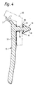
- the barbed fastener 16 shown in cross-section includes a base 24 of relatively greater cross-sectional area, a neck 26 of relatively smaller cross-section and a head 28 which, in the views of Figures 3 and 4 is in the shape of an arrow, having a pointed end and first and second barbs 30 at opposing sides of the head 28.
- the barbs 30 extend over the neck 26 such that, on insertion of the fastener 16 through the slot in the bumper 20, the barbs 30 are biased towards the neck 26, subsequently to extend outwardly of the neck on clearing the slot in the bumper 20.
- the spacing between the ends of the barbs 30 and the body portion 10 of the air dam is chosen so as to be less than the thickness of the bumper portion through which the fasteners 16 are passed.
- the ends of the barbs 30 are biased outwardly of the neck 26 by the bumper 20, producing a force acting to bring the barbs to their rest position.
- the transverse component of this force acts to pull the head 28 of the fastener away from the bumper 20 and hence the body portion 10 closer to the bumper 20.
- the barbs 30 act as biasing means for biasing the air dam towards the bumper.
- the bumper edge 12 of the air dam is in the form of a resilient flap which is deformed by the bumper 20 from the position shown in dotted outline to the position shown in solid form.
- the flap 12 is of known type so is not described in further detail herein.
- a groove 32 extends along the length of the body portion 10 of the air dam to give added elasticity.
- the tension provided by the straps 18 and the fasteners 16 causes the air dam to be substantially flat along the bumper 20.
- any stretching or slight realignment of the air dam is taken up by the elasticity of the straps 18 and by the barbs 30 of the fasteners 16.
- a preferred material for the air dam is a plastics material called Santopren (TM), which is commonly available. Any other suitable material may be used.
- TM Santopren
Landscapes
- Engineering & Computer Science (AREA)
- Chemical & Material Sciences (AREA)
- Combustion & Propulsion (AREA)
- Transportation (AREA)
- Mechanical Engineering (AREA)
- Connection Of Plates (AREA)
- Body Structure For Vehicles (AREA)
- Cooling, Air Intake And Gas Exhaust, And Fuel Tank Arrangements In Propulsion Units (AREA)
- Measuring Fluid Pressure (AREA)
Claims (7)
- Fahrzeugspoiler mit einem länglichen Körperteil (10) und einer Vielzahl von Befestigungselementen (16), die sich von einer Seite des Körperteils erstrecken und voneinander beabstandet sind, wobei die Befestigungselemente wirksam sind, den Spoiler an der Fahrzeugstruktur (20) zu befestigen, und ein Vorspannungsmittel (30) umfassen, das wirksam ist, wenn der Spoiler an der Fahrzeugstruktur befestigt ist, den Spoiler in Richtung der Fahrzeugstruktur vorzuspannen.
- Spoiler nach Anspruch 1, worin die Befestigungselemente (16) integral mit dem Körperteil (10) sind.
- Spoiler nach Anspruch 1 oder 2, worin jedes Vorspannungsmittel einen oder mehrere Widerhaken (30) umfaßt, die mit der Fahrzeugstruktur (20) zusammenarbeiten können.
- Spoiler nach Anspruch 1, 2 oder 3, worin jedes Befestigungselement (16) einen länglichen Kopf (28) und erste und zweite Widerhaken (30) auf entgegengesetzten Seiten des Kopfes umfaßt, wobei die Widerhaken sich in Richtung des Körperteils (10) erstrecken.
- Spoiler nach einem der vorhergehenden Ansprüche mit ersten und zweiten Bändern (18), die sich von jeweiligen Enden des Körperteils (10) erstrecken und integral damit ausgebildet sind, wobei jedes Band mit ersten und zweiten, mit Widerhaken versehenen Seiten ausgebildet ist.
- Spoiler nach einem der vorhergehenden Ansprüche, worin die Befestigungselemente (16) und/oder Bänder (18) aus einem Kunststoffmaterial gebildet sind.
- Fahrzeugspoiler mit einem länglichen Körperteil (10) und ersten und zweiten Bändern (18), die sich von entgegengesetzten Enden des Körperteils erstrecken und integral damit ausgebildet sind, wobei jedes Band erste und zweite, mit Widerhaken versehene Seiten umfaßt, die wirksam sind, wenn der Spoiler an der Fahrzeugstruktur (20) befestigt ist, den Spoiler an der Fahrzeugstruktur zu sichern.
Applications Claiming Priority (2)
| Application Number | Priority Date | Filing Date | Title |
|---|---|---|---|
| GB9400825A GB2285607B (en) | 1994-01-18 | 1994-01-18 | Vehicle air dam |
| GB9400825 | 1994-01-18 |
Publications (2)
| Publication Number | Publication Date |
|---|---|
| EP0664251A1 EP0664251A1 (de) | 1995-07-26 |
| EP0664251B1 true EP0664251B1 (de) | 1997-09-03 |
Family
ID=10748913
Family Applications (1)
| Application Number | Title | Priority Date | Filing Date |
|---|---|---|---|
| EP94203698A Expired - Lifetime EP0664251B1 (de) | 1994-01-18 | 1994-12-20 | Spoiler für ein Fahrzeug |
Country Status (4)
| Country | Link |
|---|---|
| EP (1) | EP0664251B1 (de) |
| DE (1) | DE69405374T2 (de) |
| ES (1) | ES2105500T3 (de) |
| GB (1) | GB2285607B (de) |
Families Citing this family (1)
| Publication number | Priority date | Publication date | Assignee | Title |
|---|---|---|---|---|
| FR3068951B1 (fr) * | 2017-07-12 | 2019-07-19 | Psa Automobiles Sa | Vehicule comprenant une lame aerodynamique fixee a un deflecteur de pare-chocs avant |
Family Cites Families (11)
| Publication number | Priority date | Publication date | Assignee | Title |
|---|---|---|---|---|
| DE1815655B1 (de) * | 1968-12-19 | 1970-07-23 | Continental Gummi Werke Ag | Stossstange fuer Kraftfahrzeuge |
| GB1583701A (en) * | 1978-05-09 | 1981-01-28 | Grant Motor Accessories Ltd Ri | Vehicle spoiler and method of mounting same |
| JPS5747256A (en) * | 1980-07-30 | 1982-03-18 | Nissan Motor Co Ltd | Guard molding for car |
| JPS5919640Y2 (ja) * | 1980-10-13 | 1984-06-07 | 日産自動車株式会社 | モ−ルデイングの固定構造 |
| JPS5787768A (en) * | 1980-11-19 | 1982-06-01 | Honda Motor Co Ltd | Automobile with spoiler |
| FR2516884A1 (fr) * | 1981-11-23 | 1983-05-27 | Mure Guy | Nouveau moyen de fixation sans percage des becquets |
| DE8505038U1 (de) * | 1985-02-22 | 1985-05-15 | Dr.Ing.H.C. F. Porsche Ag, 7000 Stuttgart | Aerodynamische verkleidung an der unterseite von personenwagen |
| JPS6256809U (de) * | 1985-09-30 | 1987-04-08 | ||
| US4652032A (en) * | 1985-10-16 | 1987-03-24 | Borg-Warner Chemicals, Inc. | Vehicle bumper assembly |
| JPS63110078A (ja) * | 1986-10-27 | 1988-05-14 | Tsutomu Miwa | 下垂式エヤダムスカ−ト |
| US4976489A (en) * | 1990-03-26 | 1990-12-11 | General Motors Corporation | Air velocity responsive self deploying flexing air dam |
-
1994
- 1994-01-18 GB GB9400825A patent/GB2285607B/en not_active Expired - Fee Related
- 1994-12-20 ES ES94203698T patent/ES2105500T3/es not_active Expired - Lifetime
- 1994-12-20 DE DE69405374T patent/DE69405374T2/de not_active Expired - Fee Related
- 1994-12-20 EP EP94203698A patent/EP0664251B1/de not_active Expired - Lifetime
Also Published As
| Publication number | Publication date |
|---|---|
| GB2285607B (en) | 1996-01-17 |
| DE69405374D1 (de) | 1997-10-09 |
| GB2285607A (en) | 1995-07-19 |
| ES2105500T3 (es) | 1997-10-16 |
| GB9400825D0 (en) | 1994-03-16 |
| DE69405374T2 (de) | 1998-01-08 |
| EP0664251A1 (de) | 1995-07-26 |
Similar Documents
| Publication | Publication Date | Title |
|---|---|---|
| KR860001416Y1 (ko) | 조정가능한 스트랩 체결구 | |
| EP2081798B1 (de) | Montagesystem für eine airbag-anordnung | |
| US4795116A (en) | Fastener for cable strap | |
| CA1100116A (en) | Developments in fixing devices | |
| US5453309A (en) | Extruded molding trim for vehicles, appliances and the like | |
| US20050016116A1 (en) | One-piece integrated snap fastening mechanism | |
| US6209907B1 (en) | Device for fixing a gas bag in its folded position and a side gas bag module | |
| US20080250609A1 (en) | Cable Tie With Insert Fastener | |
| US20110030180A1 (en) | Buckle | |
| JP2002519591A (ja) | 留めクリップ | |
| US5033216A (en) | Sign assembly | |
| JPH09135709A (ja) | ウェブの保持および調節方法と、保持および調節装置 | |
| US6668433B1 (en) | Shield for quick release fastener | |
| US7296327B2 (en) | Buckle assembly | |
| US4819303A (en) | Belt loop stay | |
| EP0664251B1 (de) | Spoiler für ein Fahrzeug | |
| KR0179435B1 (ko) | 시이트형 제품을 위한 시이트 파스너 | |
| US20200224686A1 (en) | Edge protector | |
| US4360943A (en) | Retention clip | |
| JPH04231974A (ja) | 可撓性支持ラグ及び連結部材 | |
| AU677794B2 (en) | Airfoil for a windscreen wiper blade | |
| US6799744B1 (en) | Clip structure for supporting ornamental items on a pew support | |
| US4179859A (en) | Molding retaining clip | |
| US20070113452A1 (en) | Note holder and method of making same | |
| US2876971A (en) | Means for securing ceiling panels in automobiles |
Legal Events
| Date | Code | Title | Description |
|---|---|---|---|
| PUAI | Public reference made under article 153(3) epc to a published international application that has entered the european phase |
Free format text: ORIGINAL CODE: 0009012 |
|
| AK | Designated contracting states |
Kind code of ref document: A1 Designated state(s): DE ES FR IT |
|
| 17P | Request for examination filed |
Effective date: 19960126 |
|
| RAP1 | Party data changed (applicant data changed or rights of an application transferred) |
Owner name: DELPHI - COMPONENTES, SOCIEDAD ANONIMA |
|
| GRAG | Despatch of communication of intention to grant |
Free format text: ORIGINAL CODE: EPIDOS AGRA |
|
| 17Q | First examination report despatched |
Effective date: 19961212 |
|
| GRAH | Despatch of communication of intention to grant a patent |
Free format text: ORIGINAL CODE: EPIDOS IGRA |
|
| GRAH | Despatch of communication of intention to grant a patent |
Free format text: ORIGINAL CODE: EPIDOS IGRA |
|
| GRAA | (expected) grant |
Free format text: ORIGINAL CODE: 0009210 |
|
| AK | Designated contracting states |
Kind code of ref document: B1 Designated state(s): DE ES FR IT |
|
| PG25 | Lapsed in a contracting state [announced via postgrant information from national office to epo] |
Ref country code: FR Free format text: THE PATENT HAS BEEN ANNULLED BY A DECISION OF A NATIONAL AUTHORITY Effective date: 19970903 |
|
| REF | Corresponds to: |
Ref document number: 69405374 Country of ref document: DE Date of ref document: 19971009 |
|
| ET | Fr: translation filed | ||
| REG | Reference to a national code |
Ref country code: ES Ref legal event code: FG2A Ref document number: 2105500 Country of ref document: ES Kind code of ref document: T3 |
|
| PLBE | No opposition filed within time limit |
Free format text: ORIGINAL CODE: 0009261 |
|
| STAA | Information on the status of an ep patent application or granted ep patent |
Free format text: STATUS: NO OPPOSITION FILED WITHIN TIME LIMIT |
|
| 26N | No opposition filed | ||
| PG25 | Lapsed in a contracting state [announced via postgrant information from national office to epo] |
Ref country code: DE Free format text: LAPSE BECAUSE OF NON-PAYMENT OF DUE FEES Effective date: 19980901 |
|
| REG | Reference to a national code |
Ref country code: FR Ref legal event code: ST |
|
| PG25 | Lapsed in a contracting state [announced via postgrant information from national office to epo] |
Ref country code: ES Free format text: LAPSE BECAUSE OF NON-PAYMENT OF DUE FEES Effective date: 19981221 |
|
| REG | Reference to a national code |
Ref country code: ES Ref legal event code: FD2A Effective date: 19990114 |
|
| PG25 | Lapsed in a contracting state [announced via postgrant information from national office to epo] |
Ref country code: IT Free format text: LAPSE BECAUSE OF NON-PAYMENT OF DUE FEES;WARNING: LAPSES OF ITALIAN PATENTS WITH EFFECTIVE DATE BEFORE 2007 MAY HAVE OCCURRED AT ANY TIME BEFORE 2007. THE CORRECT EFFECTIVE DATE MAY BE DIFFERENT FROM THE ONE RECORDED. Effective date: 20051220 |