EP0664255A1 - Système de retenue pour avion - Google Patents
Système de retenue pour avion Download PDFInfo
- Publication number
- EP0664255A1 EP0664255A1 EP95300400A EP95300400A EP0664255A1 EP 0664255 A1 EP0664255 A1 EP 0664255A1 EP 95300400 A EP95300400 A EP 95300400A EP 95300400 A EP95300400 A EP 95300400A EP 0664255 A1 EP0664255 A1 EP 0664255A1
- Authority
- EP
- European Patent Office
- Prior art keywords
- aircraft
- restraining
- beams
- deck
- restraining system
- Prior art date
- Legal status (The legal status is an assumption and is not a legal conclusion. Google has not performed a legal analysis and makes no representation as to the accuracy of the status listed.)
- Granted
Links
- 230000000452 restraining effect Effects 0.000 title claims abstract description 46
- 230000007246 mechanism Effects 0.000 description 7
- 229910001220 stainless steel Inorganic materials 0.000 description 6
- 239000010935 stainless steel Substances 0.000 description 6
- 238000006073 displacement reaction Methods 0.000 description 4
- 230000003134 recirculating effect Effects 0.000 description 3
- 238000005461 lubrication Methods 0.000 description 2
- 239000011359 shock absorbing material Substances 0.000 description 2
- CMKDJMDGRSJZIS-UHFFFAOYSA-N 2,3-dihydro-1h-indene-1-carbaldehyde Chemical compound C1=CC=C2C(C=O)CCC2=C1 CMKDJMDGRSJZIS-UHFFFAOYSA-N 0.000 description 1
- 229920001780 ECTFE Polymers 0.000 description 1
- 238000011109 contamination Methods 0.000 description 1
- 238000013016 damping Methods 0.000 description 1
- 231100001261 hazardous Toxicity 0.000 description 1
- 238000012423 maintenance Methods 0.000 description 1
- 238000000034 method Methods 0.000 description 1
- 238000012986 modification Methods 0.000 description 1
- 230000004048 modification Effects 0.000 description 1
- 229920002635 polyurethane Polymers 0.000 description 1
- 239000004814 polyurethane Substances 0.000 description 1
- 239000000523 sample Substances 0.000 description 1
- 230000035939 shock Effects 0.000 description 1
- 239000007787 solid Substances 0.000 description 1
- 239000000126 substance Substances 0.000 description 1
- 230000001360 synchronised effect Effects 0.000 description 1
Images



Classifications
-
- B—PERFORMING OPERATIONS; TRANSPORTING
- B64—AIRCRAFT; AVIATION; COSMONAUTICS
- B64F—GROUND OR AIRCRAFT-CARRIER-DECK INSTALLATIONS SPECIALLY ADAPTED FOR USE IN CONNECTION WITH AIRCRAFT; DESIGNING, MANUFACTURING, ASSEMBLING, CLEANING, MAINTAINING OR REPAIRING AIRCRAFT, NOT OTHERWISE PROVIDED FOR; HANDLING, TRANSPORTING, TESTING OR INSPECTING AIRCRAFT COMPONENTS, NOT OTHERWISE PROVIDED FOR
- B64F1/00—Ground or aircraft-carrier-deck installations
- B64F1/12—Ground or aircraft-carrier-deck installations for anchoring aircraft
- B64F1/125—Mooring or ground handling devices for helicopters
Definitions
- the present invention relates to an aircraft restraining system for securing an aircraft on the deck of a ship.
- decklocks in the form of probes usually on the rotor axis, which may be extended on the helicopter landing on the deck of a ship to engage with a landing grid.
- the decklock operates in a harpoon-like manner and once engaged with the grid pulls the aircraft into firm engagement with deck.
- the aircraft may then be engaged by a shuttle provided on a transfer rail to allow the aircraft to be transferred from the landing deck to a storage hangar. Examples of this form of system are described in US Patent Nos 4,319,722 and 4,786,014 to Pesando and Pesando et respectively, and European Patent Application No. 0,208,439 in the name of MacTaggart Scott (Holdings) Ltd.
- French Patent No. 598,590 dating from 1925, discloses an arrangement for securing airships in which a pair of laterally spaced hooks, mounted on the upper ends of pistons, are provided for engaging eyelets provided on extendable arms on the airship.
- the arms are movable inwardly such that the eyelets may be engaged with the hooks to maintain the airship level, and when the airship is to take off the pistons may be extended before the arms themselves are extended to release the eyelets from the hooks. It is considered that such a system would be unsuitable for use on ships for securing aircraft, due to the accurate relative location of the aircraft and the hooks that would be required, and also the similarly accurately timed actuation of the arms by the aircrew when the necessary relative location was achieved.
- US Patent No. 5,248,115 to Aurelio discloses devices for gripping and handling helicopters on ships' decks including a pair of beams initially set parallel to the longitudinal axis of the ship and mounted on a pair of transverse rails. The beams are moved inwardly to engage the skids or wheels of the helicopter, the beams being pivoted to lie parallel to the longitudinal axis of the helicopter. The beams then lift the helicopter from the deck before rotating and moving the helicopter transversely to a position in which the helicopter may be engaged by a trolley mounted on a longitudinally mounted rail.
- an aircraft restraining system for securing an aircraft on the deck of a ship, the system including two elongate restraining beams transversely movable from respective storage positions for engaging at least two spaced portions of an aircraft, each restraining beam including a restraining member for engaging the respective portions of the aircraft and restricting longitudinal movement thereof, at least one of the members being actuable for movement along the respective beam, following engagement with the aircraft, to rotate the aircraft.
- the system In use, the system is used to secure an aircraft immediately it lands on the deck, and without requiring the presence of operators on the deck.
- the system will be utilised to secure helicopters landing on the decks of ships and will engage the spurs which extend laterally from the main wheels thereof, such that the aircraft fuselage will not move on the elasticity of its tyres under ship motion.
- the system will likely be used in conjunction with an aircraft decklock and the restraining beams will be actuated immediately the decklock is engaged in the landing grid provided on the deck.
- the restraining beams lie flush with or below the level of the deck, and thus do not present an inconvenient and potentially hazardous projection from the deck surface when not in use.
- the restraining beams are movable from the aircraft engaging position while remaining engaged with the aircraft.
- the aircraft may remain secured on the deck as it is, for example, moved to a location for engagement with an aircraft transfer shuttle.
- each restraining member is in the form of a latch.
- Each latch may be movable from a latch storage position along a respective beam to engage with the aircraft.
- both latches may be driven such that the aircraft may be rotated to a limited degree by relative movement of the latches along the respective beams, and thus said parts of the aircraft along the beams, accompanied by appropriate transverse movement of at least one of the beams.
- the aircraft When operated in conjunction with a decklock, the aircraft may be rotated about the engaged decklock.
- transversely extending portions such as main wheel spurs
- rotation of the aircraft to an orientation parallel with the centre-line of the ship will optimise the length of the portions engaged with the restraining beams.
- the system further includes means for transferring the aircraft from the landing area and the restraining beams are movable to bring the portions of the aircraft to engage with the transfer means.
- the transfer means includes respective shuttles for engaging said portions of the aircraft.
- said shuttles are also arranged to secure the aircraft against toppling and are movable along respective transversely spaced tracks.
- the transfer means may include a traversing frame movable along a single track.
- the system includes transversely movable supports for the main wheels of the aircraft to permit transverse movement of the secured aircraft, for alignment with the aircraft transfer means.
- FIG. 1 of the drawings illustrates an aircraft restraining and handling system 10 in accordance with a preferred embodiment of the present invention.
- the system 10 is, in this example, provided on the deck of a ship 12 and is utilised for securing the helicopter on landing on the deck 13, and then moving the helicopter to a position suitable for engaging with an aircraft transfer system for moving the helicopter from a landing area of the deck 13 to a hangar (not shown), as will be described in greater detail below.
- the system 10 includes a conventional landing grid 14 located in the centre of the deck landing area 13.
- the grid 14 defines a number of openings adapted to receive and engage a decklock as provided on the helicopter.
- the decklock is extended on landing the helicopter on the deck to engage with the grid 14 in a harpoon-like manner to provide initial securement of the helicopter on the deck. In most helicopters the decklock is aligned with the rotor axis, midway between the main wheels 16, 18 of the helicopter.
- Figure 1 illustrates the location of the main wheels 16a, 18a and the nose wheel 20a of a helicopter which has landed with its decklock 22 in the centre of the landing grid 14 and the longitudinal axis of the helicopter 24a parallel the main axis of the ship 26.
- accuracy is very difficult to achieve, particularly in anything other than flat calm conditions, and the other illustrated starboard main wheels 16 show the "landing scatter" which would typically be encountered.
- the wheels 16 shown in solid outline illustrate a 15° offset from the ship's axis while the wheels 16 shown in broken outline illustrate a 20° offset.
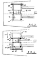
- FIGS. 2a and 2b of the drawings illustrate, in cross-section, one of two restraining beams 28, 30 forming part of the restraining system.
- the beam 28 will be described as exemplary of both.
- the beams 28, 30 are located outboard of the landing grid 14 and outboard of the wheel landing area 13 and, when not in use, occupy a storage position within deck recesses 29, 31, as shown in Figure 2a, in which the upper surface of the beam 28 is flush with the surface of the deck 12.
- the beam 28 includes a deck plate 32 which provides a smooth and continuous deck surface when the beam 28 is in the storage position.
- the beam 28 of this example is approximately 5.5 metres long.
- the beam 28 is attached to two rotatable brackets 33, 34, each bracket 33, 34 being driven by a pair of stainless steel recirculating roller screws 35 (only one shown).
- the four screws provided for each beam 28, 30 are mechanically synchronised to each other and their displacement is measured by appropriate shaft encoders 36.
- Drive for the screws 35 is provided by hydraulic motor 37.
- Such stainless steel recirculating roller screws have been used successfully in other off-shore applications and accommodate the marine environment without difficulty; furthermore, they are well able to cope with shock and are suitable for operation in applications likely to experience contamination with dirt, ice, chemical deposit or poor lubrication.
- the other drive arrangements such as belts, roller chains, cables and the like may be provided for the beams.
- the beams may themselves be provided with drive motors for driving, for example, pinions engaging racks formed on the deck.
- the beam 28 defines a box-section 46 and an inboard channel section 47.
- the inboard face of each beam channel 47 is provided with a layer of shock absorbing material 51.
- a latching mechanism 48 is constrained to slide along its length.
- a further stainless steel recirculating roller screw 49 is used to drive the latching mechanism 48, in a similar manner to a lead screw of a machine tool.
- the drive to the latching mechanism screw 49 is provided by a stainless steel roller link chain 50 ( Figure 1) which runs within the height of the rail and is brought up to and returned from the screw via idling sprockets mounted on each aft bracket 33.
- the chain 50 itself is driven by a hydraulic motor 52 and the position of the latching mechanism 48 along the beam 28 is determined via a shaft encoder 53.
- the beam rail sections 54 are of stainless steel and each accommodate two beam drive screws 35 and the inboard rollers 40 of the respective bracket 33, 34.
- the outboard rollers 44 roll on the top face of the rail sections.
- the beam rails 42, 43 are covered by a hinged flap when not in use, in order to keep out foreign objects.
- a hinged traversing plate 55 (approximately 0.5 m x 0.5 m ) is provided and slides on top of the forward beam rails.
- a bearing such as the TURCITE (TM) bearing supplied by (COMPANY NAME) of (TOWN & COUNTRY) facilitates movement of the plate over the rail.
- the main wheels are rolled on to the respective plates 55.
- FIG. 1 Also shown in Figure 1 are three transfer rails 58, 60, 62 which lead to the hangar (not shown). Each rail 58, 60, 62 is provided with a respective shuttle 59, 61, 63 ( Figure 8) adapted to engage the main wheels and nose wheel 16, 18, 20 of the helicopter, to transfer the secured helicopter from the deck 12 to the hangar.
- Each rail 58, 60, 62 is provided with a respective shuttle 59, 61, 63 ( Figure 8) adapted to engage the main wheels and nose wheel 16, 18, 20 of the helicopter, to transfer the secured helicopter from the deck 12 to the hangar.
- Figure 3 illustrates the positions of the main wheels and nose wheel 16, 18, 20 of a helicopter which has landed at the extreme aft and starboard side of the grid with a heading of 15° to the ship's centre line, such that the decklock provided on the helicopter engages with the corner of the landing grid 14.
- the restraining beams 28, 30 are actuated and are lifted from their storage positions ( Figure 2a) before moving transversely inwardly along the rails 42, 43, as indicated by arrows A, B, until they contact the respective main wheels 16, 18 of the helicopter ( Figure 4).
- the beams 28, 30 are adapted to engage the spurs 64,66 which extend transversely from the wheels 16, 18.
- the spurs are located within the channel sections 47.
- the upper wall of each channel section 47 ( Figure 2b) prevents upward movement of the spurs 64, 66 and thus minimises the likelihood of the helicopter toppling on the deck 12.
- the latch mechanisms 48 provided on the beams 28, 30 are actuated and travel along the beams 28, 30 from their aft storage positions until they engage with the respective spurs 64, 66 and secure the spurs 64, 66 against longitudinal movement.
- the helicopter is securely restrained by the beams 28, 30, in addition to the engagement of the decklock in the landing grid 14.
- the helicopter After initial engagement, and possibly some degree of rotation under control of the pilot, the helicopter is rotated such that it lies parallel to the longitudinal axis of the ship 26. This requires that the nose wheel 20 is turned through 90° to the position shown in Figure 4.
- the displacement of the latches 48 from the stowed condition is known from the displacement encoders 53, and moving the latches 48 such that they have a similar displacement from the stowed positions will result in the centre line of the aircraft being parallel to that of the handling system.
- the latches 48 are actuated to move in the appropriate directions, indicated by arrows C, D, to rotate the helicopter about the decklock, the beams 28, 30 moving transversely outwardly, in the direction of arrows E, F, ( Figure 5) to accommodate versine movement. Movement of the latches continues until the helicopter is parallel with the ship axis (and handling system) 26, as illustrated in Figure 5.
- the helicopter is next moved forwardly, after releasing the decklock, utilising the latches 48, until the main wheels of the helicopter 16, 18 are located on the plates 55, as shown in Figure 6.
- the nose wheel 20 is rotated through 90°.
- the beams 28, 30 are then moved transversely, in the direction of arrows G ( Figure 7), to align the wheels with the rails 58, 60, 62.
- the aircraft nose wheel 20 is rotated back through 90° to a fore and aft position. Both main wheel shuttles 69, 61 are brought fully aft and abut against the respective beams 28, 30 and the nose wheel shuttle is brought aft to an appropriate station ( Figure 9).
- the latches 48 are then utilised to move the aircraft forwardly, from the plates 55, until the nose wheel 20 automatically engages with the nose wheel shuttle 63.
- the helicopter is then pulled forwards utilising the nose wheel shuttle 63, the latches 48 releasing the main wheel spurs 64, 66 such that the spurs may be pulled, with continuity of security, into the main wheel shuttles 59, 61, as illustrated in Figure 9.
- the helicopter may then be moved along the rails 58, 60, 62 to the aircraft hangar.
- main wheel spurs 64, 66 are secured either by the beams 28, 30 and latches 48 or the shuttles 59, 61, and thus there is minimal risk of the aircraft toppling or sliding uncontrollably on the deck 12. It will further be noted that the operation does not require the presence of operators on deck and thus reduces the risk to personnel in rough sea conditions.
- the aircraft is aligned as illustrated in Figure 7 and pulled aft by the latching mechanism to enable the decklock 22 to be engaged with the grid 14.
- the beams 28, 30 may be retracted although it is possible to enhance the security of the aircraft by keeping them in position.
- FIG. 10 to 15 illustrate an aircraft restraining and handling system in accordance with a second embodiment of the present invention.
- This second embodiment features a similar restraining beam arrangement to that described above, but is provided with a circular landing grid 14a and a simplified transfer arrangement.
- a single rail 70 is used in conjunction with a traversing frame 72.
- the frame 72 is rigidly guided by the rail 70 and may be attached, through a latching arrangement 76, to the main wheel spurs 64, 66. This provides a two point attachment to the aircraft, thus guaranteeing security against weather cocking which could occur if a single attachment point is used.
- the steering of the aircraft is controlled from the main wheel spurs 64, 66.
- roller link chain 78 Drive to the frame 72 is via a stainless steel roller link chain 78.
- the use of the roller link chain 78 enables a more accurate encoder 82 to be used for the control system 84 in place of wire pulley measuring systems which can have slippage.
- the chain 78 is supported within the rail 70 by a high density polyurethane guide channel, which eliminates the need for lubrication and which also exhibits good sound damping characteristics.
- Figure 10 is a plan view of the flight deck and shows the securing beams 28, 30 housed flush with the deck 13 and outboard of the landing grid 14a.
- FIG 11 illustrates a helicopter having landed at a 15° heading to the ship's centre-line and the decklock 22 engaged on the extreme port side of the grid 14a.
- the operator at the system control console then actuates the system. This causes the securing beam drive screws 35 to rotate the beams 28, 30 out of the deck 12 and travel inboard with a light force. Their movement is stopped when the beams 28, 30 come into contact with the main wheel spurs 64, 66 of the aircraft. The face of the beam that contacts the spur is covered with a shock absorbing material in order to reduce the beam decelerating force.
- each latching mechanism 48 travels along the beam channel 47 and automatically latches onto the spur 64, 66.
- the aircraft is now captive within the handling system with forces in the three principal dimensions being contained, thus preventing any unwanted aircraft movement.
- the pilot can now disengage the decklock 22, carry out blade folding and shut down engines.
- the traversing frame 72 can be moved aft directly into position.
- the exact disposition of the aircraft on the grid is known by the control system, though signals from the various encoders 36, 53 and therefore it will know if the traversing frame 72 can be brought into position without moving the aircraft.
- the aircraft is then rotated about the centre of the main wheel axis by the differential movement of the beam latches 48 until both latches are equally displaced, when the aircraft heading will be parallel to the system centre-line ( Figure 12).
- the securing beams 28, 30 are moved slightly outboard by the management system to accommodate the versine movement as the aircraft is rotated.
- the aircraft is then moved forward by equal movement of the latches 48 until the main wheels mount the traversing plates 55 ( Figure 13).
- the securing beams 28, 30 are next moved athwartships to bring the aircraft directly onto the ship's centre-line ( Figure 14).
- latches 48 move the aircraft forward a short distance when the spur security is transferred from the securing beam latches 48 to the traversing frame latches 76 ( Figure 15).
- the traversing frame 72 can now bring the aircraft directly into the hangar with accuracy and security.
- the aircraft For weapons handling after the aircraft has landed, the aircraft is aligned as described above in Figures 10 to 14. Since the aircraft will be re-armed and refuelled on the deck, the traversing frame 72 does not have to be attached to the main wheel spurs 64, 66. Weapon trolleys will be prepared in the magazine and brought to the hangar. The trolleys are then rigidly attached by links to the aft end of the traversing frame 72 and offset athwartships as required to reflect the weapon pylon positions. The traversing 72 frame is moved aft towards the aircraft pushing the weapon trolleys. This will bring the weapons accurately under the pylons.
- the weapon trolleys should be capable of gently lifting the weapons into position where they would automatically be locked into the pylons.
- deck personnel will be required to use manual hoists to lift the weapons into position while personnel are on deck, and in particular in severe weather they may be attached by life-line to the traversing frame for security.
Landscapes
- Engineering & Computer Science (AREA)
- Mechanical Engineering (AREA)
- Aviation & Aerospace Engineering (AREA)
- Tires In General (AREA)
Applications Claiming Priority (2)
| Application Number | Priority Date | Filing Date | Title |
|---|---|---|---|
| GB9401151 | 1994-01-21 | ||
| GB9401151A GB9401151D0 (en) | 1994-01-21 | 1994-01-21 | Aircraft restraining system |
Publications (2)
| Publication Number | Publication Date |
|---|---|
| EP0664255A1 true EP0664255A1 (fr) | 1995-07-26 |
| EP0664255B1 EP0664255B1 (fr) | 2002-12-11 |
Family
ID=10749141
Family Applications (1)
| Application Number | Title | Priority Date | Filing Date |
|---|---|---|---|
| EP95300400A Expired - Lifetime EP0664255B1 (fr) | 1994-01-21 | 1995-01-23 | Système de retenue pour avion |
Country Status (4)
| Country | Link |
|---|---|
| US (1) | US5570858A (fr) |
| EP (1) | EP0664255B1 (fr) |
| DE (1) | DE69529107D1 (fr) |
| GB (1) | GB9401151D0 (fr) |
Cited By (2)
| Publication number | Priority date | Publication date | Assignee | Title |
|---|---|---|---|---|
| EP0773158A2 (fr) | 1995-11-07 | 1997-05-14 | MacTaggart Scott (Holdings) Ltd. | Améliorations apportées à un appareil de manutention des avions |
| GB2387156A (en) * | 2002-02-14 | 2003-10-08 | Alstec Ltd | Aircraft handling system |
Families Citing this family (1)
| Publication number | Priority date | Publication date | Assignee | Title |
|---|---|---|---|---|
| FR2848526B1 (fr) * | 2002-12-17 | 2005-12-30 | Tech D Etudes Realisations Et | Dispositif d'amarrage d'un aeronef |
Citations (3)
| Publication number | Priority date | Publication date | Assignee | Title |
|---|---|---|---|---|
| US3291422A (en) * | 1965-05-05 | 1966-12-13 | James F Van Valkenburg | Aligning and centering device for helicopter |
| DE2802231A1 (de) * | 1977-01-20 | 1978-07-27 | Daf Indal Ltd | Vorrichtung und verfahren zum verschieben und verstauen von hubschraubern |
| US5248115A (en) * | 1991-06-12 | 1993-09-28 | Riva Calzoni S.P.A. | Device for gripping and handling helicopters, particularly for ships' decks, platforms and the like |
Family Cites Families (15)
| Publication number | Priority date | Publication date | Assignee | Title |
|---|---|---|---|---|
| FR598590A (fr) * | 1925-02-24 | 1925-12-19 | Dispositif d'amarrage pour aéronefs plus légers que l'air | |
| CA900447A (en) * | 1969-01-21 | 1972-05-16 | Baekken Asbjorn | Ship-borne load conveying means |
| US3830452A (en) * | 1973-06-22 | 1974-08-20 | Kaman Aerospace Corp | Monorail traverse system |
| US4123020A (en) * | 1976-02-23 | 1978-10-31 | Kazimierz Korsak | VTOL launching and retrieval systems |
| US4319722A (en) * | 1979-05-07 | 1982-03-16 | Mario Pesando | Traverser and components therefor |
| GB2075931B (en) * | 1980-05-09 | 1983-10-12 | Daf Indal Ltd | Helicopter traverser and traversing system |
| US4420132A (en) * | 1981-06-12 | 1983-12-13 | Martin Gerald J | Securing device for helicopters and the like |
| NZ202251A (en) * | 1981-10-22 | 1985-01-31 | Commw Austral Defence Support | Winch system:moving trolleys mounted on rails between pairs of winches |
| FR2532910A1 (fr) * | 1982-09-13 | 1984-03-16 | Aerospatiale | Dispositifs de manoeuvre d'helicopteres sur le pont d'un navire |
| GB8515708D0 (en) * | 1985-06-20 | 1986-08-20 | Mactaggart Scott | Aircraft handling systems on ships |
| CA1278288C (fr) * | 1985-11-04 | 1990-12-27 | Mario Pesando | Systeme d'arrimage et rangement rapides d'helicopteres |
| FR2660282B1 (fr) * | 1990-03-29 | 1992-07-31 | Aerospatiale | Dispositif de manóoeuvre d'un engin supporte par un train principal et au moins une roue orientable, tel qu'un helicoptere, entre deux zones determinees sur une plate-forme, telles qu'une aire d'appontage et une aire de garage sur un pont de navire. |
| GB9008969D0 (en) * | 1990-04-21 | 1990-06-20 | Mactaggart Scott | Aircraft traversing system |
| US5347947A (en) * | 1991-05-14 | 1994-09-20 | Craig Thomas M | Apparatus for controlling aircraft on ships or the like |
| GB9204987D0 (en) * | 1992-03-07 | 1992-04-22 | Mactaggart Scott | Improvements in or relating to load transportation apparatus |
-
1994
- 1994-01-21 GB GB9401151A patent/GB9401151D0/en active Pending
-
1995
- 1995-01-20 US US08/376,594 patent/US5570858A/en not_active Expired - Fee Related
- 1995-01-23 EP EP95300400A patent/EP0664255B1/fr not_active Expired - Lifetime
- 1995-01-23 DE DE69529107T patent/DE69529107D1/de not_active Expired - Lifetime
Patent Citations (3)
| Publication number | Priority date | Publication date | Assignee | Title |
|---|---|---|---|---|
| US3291422A (en) * | 1965-05-05 | 1966-12-13 | James F Van Valkenburg | Aligning and centering device for helicopter |
| DE2802231A1 (de) * | 1977-01-20 | 1978-07-27 | Daf Indal Ltd | Vorrichtung und verfahren zum verschieben und verstauen von hubschraubern |
| US5248115A (en) * | 1991-06-12 | 1993-09-28 | Riva Calzoni S.P.A. | Device for gripping and handling helicopters, particularly for ships' decks, platforms and the like |
Cited By (3)
| Publication number | Priority date | Publication date | Assignee | Title |
|---|---|---|---|---|
| EP0773158A2 (fr) | 1995-11-07 | 1997-05-14 | MacTaggart Scott (Holdings) Ltd. | Améliorations apportées à un appareil de manutention des avions |
| EP0773158A3 (fr) * | 1995-11-07 | 1999-04-14 | MacTaggart Scott (Holdings) Ltd. | Améliorations apportées à un appareil de manutention des avions |
| GB2387156A (en) * | 2002-02-14 | 2003-10-08 | Alstec Ltd | Aircraft handling system |
Also Published As
| Publication number | Publication date |
|---|---|
| DE69529107D1 (de) | 2003-01-23 |
| US5570858A (en) | 1996-11-05 |
| GB9401151D0 (en) | 1994-03-16 |
| EP0664255B1 (fr) | 2002-12-11 |
Similar Documents
| Publication | Publication Date | Title |
|---|---|---|
| US4529152A (en) | Devices for maneuvering helicopters on a ship's deck | |
| US5000398A (en) | Flying multi-purpose aircraft carrier and method of V/STOL assisted flight | |
| DK2969883T3 (en) | WEATHER MAINTENANCE SYSTEM FOR A OFFSHORE WINDMILL MAINTENANCE PROGRAM | |
| US2488051A (en) | Aircraft landing apparatus | |
| US8485468B2 (en) | Ground-based apparatus for the take-off, landing and taxiing of aircraft | |
| US20110070045A1 (en) | Cargo container handling system and associated method | |
| US3640490A (en) | Shipborne conveying means | |
| US6019314A (en) | Aircraft handling apparatus | |
| US4325317A (en) | Aircraft carrier | |
| US12522353B2 (en) | Attachment sub-systems for vertically-stacked multicopters | |
| AU2010299733B2 (en) | System for loading/unloading a vehicle into/from carrier ship, and corresponding carrier ship | |
| US3468280A (en) | Ramp for lst | |
| EP0664255B1 (fr) | Système de retenue pour avion | |
| US3075731A (en) | Aircraft anchor device | |
| US4234143A (en) | Traversing and housing system for helicopters | |
| US5218921A (en) | Aircraft carrier | |
| US2412729A (en) | Aircraft load handling system | |
| US5102091A (en) | Aircraft traversing system | |
| US4787574A (en) | Aircraft handling systems on ships | |
| GB2264680A (en) | Transportation apparatus for handling aircraft on a deck. | |
| US3540677A (en) | Method and apparatus for launching and retrieving boats and personnel | |
| GB2264908A (en) | Apparatus for aligning and traversing an aircraft on the deck of a ship. | |
| US20190168865A1 (en) | Nose gear steering apparatus for shipboard operations | |
| US2020324A (en) | Method and apparatus for launching seaplanes | |
| CA1140519A (fr) | Chariot de manoeuvre d'helicoptere sur ponts de navires |
Legal Events
| Date | Code | Title | Description |
|---|---|---|---|
| PUAI | Public reference made under article 153(3) epc to a published international application that has entered the european phase |
Free format text: ORIGINAL CODE: 0009012 |
|
| AK | Designated contracting states |
Kind code of ref document: A1 Designated state(s): DE FR GB IT |
|
| 17P | Request for examination filed |
Effective date: 19951222 |
|
| 17Q | First examination report despatched |
Effective date: 19970520 |
|
| GRAG | Despatch of communication of intention to grant |
Free format text: ORIGINAL CODE: EPIDOS AGRA |
|
| GRAG | Despatch of communication of intention to grant |
Free format text: ORIGINAL CODE: EPIDOS AGRA |
|
| GRAH | Despatch of communication of intention to grant a patent |
Free format text: ORIGINAL CODE: EPIDOS IGRA |
|
| GRAH | Despatch of communication of intention to grant a patent |
Free format text: ORIGINAL CODE: EPIDOS IGRA |
|
| GRAA | (expected) grant |
Free format text: ORIGINAL CODE: 0009210 |
|
| AK | Designated contracting states |
Kind code of ref document: B1 Designated state(s): DE FR GB IT |
|
| PG25 | Lapsed in a contracting state [announced via postgrant information from national office to epo] |
Ref country code: IT Free format text: LAPSE BECAUSE OF FAILURE TO SUBMIT A TRANSLATION OF THE DESCRIPTION OR TO PAY THE FEE WITHIN THE PRESCRIBED TIME-LIMIT;WARNING: LAPSES OF ITALIAN PATENTS WITH EFFECTIVE DATE BEFORE 2007 MAY HAVE OCCURRED AT ANY TIME BEFORE 2007. THE CORRECT EFFECTIVE DATE MAY BE DIFFERENT FROM THE ONE RECORDED. Effective date: 20021211 Ref country code: FR Free format text: LAPSE BECAUSE OF NON-PAYMENT OF DUE FEES Effective date: 20021211 |
|
| REG | Reference to a national code |
Ref country code: GB Ref legal event code: FG4D |
|
| REF | Corresponds to: |
Ref document number: 69529107 Country of ref document: DE Date of ref document: 20030123 |
|
| PG25 | Lapsed in a contracting state [announced via postgrant information from national office to epo] |
Ref country code: GB Free format text: LAPSE BECAUSE OF NON-PAYMENT OF DUE FEES Effective date: 20030311 |
|
| PG25 | Lapsed in a contracting state [announced via postgrant information from national office to epo] |
Ref country code: DE Free format text: LAPSE BECAUSE OF FAILURE TO SUBMIT A TRANSLATION OF THE DESCRIPTION OR TO PAY THE FEE WITHIN THE PRESCRIBED TIME-LIMIT Effective date: 20030312 |
|
| PLBE | No opposition filed within time limit |
Free format text: ORIGINAL CODE: 0009261 |
|
| STAA | Information on the status of an ep patent application or granted ep patent |
Free format text: STATUS: NO OPPOSITION FILED WITHIN TIME LIMIT |
|
| GBPC | Gb: european patent ceased through non-payment of renewal fee |
Effective date: 20030311 |
|
| EN | Fr: translation not filed | ||
| 26N | No opposition filed |
Effective date: 20030912 |