EP0664377A1 - Verfahren zur verbesserung einer dampfturbine und dampfkreislauf kombiniertensystems mit einer fosilen primärenergiequelle - Google Patents
Verfahren zur verbesserung einer dampfturbine und dampfkreislauf kombiniertensystems mit einer fosilen primärenergiequelle Download PDFInfo
- Publication number
- EP0664377A1 EP0664377A1 EP94907572A EP94907572A EP0664377A1 EP 0664377 A1 EP0664377 A1 EP 0664377A1 EP 94907572 A EP94907572 A EP 94907572A EP 94907572 A EP94907572 A EP 94907572A EP 0664377 A1 EP0664377 A1 EP 0664377A1
- Authority
- EP
- European Patent Office
- Prior art keywords
- vapor
- reheating
- cycle
- pressure
- steam
- Prior art date
- Legal status (The legal status is an assumption and is not a legal conclusion. Google has not performed a legal analysis and makes no representation as to the accuracy of the status listed.)
- Withdrawn
Links
- 238000000034 method Methods 0.000 title claims abstract description 24
- 239000007789 gas Substances 0.000 claims abstract description 46
- 238000003303 reheating Methods 0.000 claims abstract description 38
- XLYOFNOQVPJJNP-UHFFFAOYSA-N water Substances O XLYOFNOQVPJJNP-UHFFFAOYSA-N 0.000 claims abstract description 23
- 239000000203 mixture Substances 0.000 claims abstract description 19
- 239000012530 fluid Substances 0.000 claims abstract description 12
- 230000008569 process Effects 0.000 claims description 22
- 238000010438 heat treatment Methods 0.000 claims description 20
- 239000000126 substance Substances 0.000 claims description 18
- 230000008016 vaporization Effects 0.000 claims description 18
- 238000009834 vaporization Methods 0.000 claims description 15
- 239000002918 waste heat Substances 0.000 claims description 9
- 238000009833 condensation Methods 0.000 claims description 5
- 230000005494 condensation Effects 0.000 claims description 5
- 230000009466 transformation Effects 0.000 claims description 4
- 229920006395 saturated elastomer Polymers 0.000 claims description 2
- 239000007788 liquid Substances 0.000 abstract description 2
- 238000004064 recycling Methods 0.000 abstract 2
- 238000010025 steaming Methods 0.000 abstract 1
- 238000011084 recovery Methods 0.000 description 13
- 230000008901 benefit Effects 0.000 description 7
- 230000009467 reduction Effects 0.000 description 5
- 238000001816 cooling Methods 0.000 description 4
- 239000002803 fossil fuel Substances 0.000 description 4
- 238000010521 absorption reaction Methods 0.000 description 3
- 238000002485 combustion reaction Methods 0.000 description 3
- 238000000605 extraction Methods 0.000 description 3
- 239000010813 municipal solid waste Substances 0.000 description 3
- 239000002028 Biomass Substances 0.000 description 2
- 230000005540 biological transmission Effects 0.000 description 2
- 239000000567 combustion gas Substances 0.000 description 2
- 238000013461 design Methods 0.000 description 2
- 230000006866 deterioration Effects 0.000 description 2
- 238000010586 diagram Methods 0.000 description 2
- ZUOUZKKEUPVFJK-UHFFFAOYSA-N diphenyl Chemical compound C1=CC=CC=C1C1=CC=CC=C1 ZUOUZKKEUPVFJK-UHFFFAOYSA-N 0.000 description 2
- 239000007791 liquid phase Substances 0.000 description 2
- 238000012423 maintenance Methods 0.000 description 2
- VNWKTOKETHGBQD-UHFFFAOYSA-N methane Chemical compound C VNWKTOKETHGBQD-UHFFFAOYSA-N 0.000 description 2
- 238000005457 optimization Methods 0.000 description 2
- 238000009738 saturating Methods 0.000 description 2
- 238000012546 transfer Methods 0.000 description 2
- 238000000844 transformation Methods 0.000 description 2
- 230000006978 adaptation Effects 0.000 description 1
- 238000013459 approach Methods 0.000 description 1
- 235000010290 biphenyl Nutrition 0.000 description 1
- 239000004305 biphenyl Substances 0.000 description 1
- 238000009835 boiling Methods 0.000 description 1
- 238000006243 chemical reaction Methods 0.000 description 1
- USIUVYZYUHIAEV-UHFFFAOYSA-N diphenyl ether Chemical compound C=1C=CC=CC=1OC1=CC=CC=C1 USIUVYZYUHIAEV-UHFFFAOYSA-N 0.000 description 1
- 230000005611 electricity Effects 0.000 description 1
- 230000008030 elimination Effects 0.000 description 1
- 238000003379 elimination reaction Methods 0.000 description 1
- 238000005516 engineering process Methods 0.000 description 1
- 230000007613 environmental effect Effects 0.000 description 1
- 230000003628 erosive effect Effects 0.000 description 1
- 239000000374 eutectic mixture Substances 0.000 description 1
- 230000002349 favourable effect Effects 0.000 description 1
- 239000000446 fuel Substances 0.000 description 1
- 230000006872 improvement Effects 0.000 description 1
- 239000000463 material Substances 0.000 description 1
- 238000002156 mixing Methods 0.000 description 1
- 239000003345 natural gas Substances 0.000 description 1
- 238000010248 power generation Methods 0.000 description 1
- 230000001172 regenerating effect Effects 0.000 description 1
Images


Classifications
-
- F—MECHANICAL ENGINEERING; LIGHTING; HEATING; WEAPONS; BLASTING
- F01—MACHINES OR ENGINES IN GENERAL; ENGINE PLANTS IN GENERAL; STEAM ENGINES
- F01K—STEAM ENGINE PLANTS; STEAM ACCUMULATORS; ENGINE PLANTS NOT OTHERWISE PROVIDED FOR; ENGINES USING SPECIAL WORKING FLUIDS OR CYCLES
- F01K23/00—Plants characterised by more than one engine delivering power external to the plant, the engines being driven by different fluids
- F01K23/02—Plants characterised by more than one engine delivering power external to the plant, the engines being driven by different fluids the engine cycles being thermally coupled
- F01K23/06—Plants characterised by more than one engine delivering power external to the plant, the engines being driven by different fluids the engine cycles being thermally coupled combustion heat from one cycle heating the fluid in another cycle
- F01K23/10—Plants characterised by more than one engine delivering power external to the plant, the engines being driven by different fluids the engine cycles being thermally coupled combustion heat from one cycle heating the fluid in another cycle with exhaust fluid of one cycle heating the fluid in another cycle
Definitions
- the invention relates to a process for improving the combination between a gas turbine and a steam cycle that uses an additional non-fossil fuel as primary energy, applicable to electric power plants or electricity and thermal energy cogeneration plants employing at least two primary energy sources: an appropriated fuel for the gas turbine and an additional non-fossil fuel (refuse, geothermal, biomass, solar energy, etc.) for the steam cycle.
- the invention proposed herein applicable to all those cases in which the practice of intermediate reheating using the primary non-fossil energy source is not techno-economically feasible, gives a limited cost effectiveness or presents appreciable technical risks, consists in applying an intermediate reheating of the steam cycle by means of the waste heat of gas turbine exhaust gases in their high-temperature range.
- the proposed schematic offers a number of advantages which, in general, considerably improve the conditions under which the reheating could be carried out using non-fossil primary energy, provided that this would be feasible, as here the steam reheating at relatively low pressure and temperature may be carried out near the steam turbine, in a typical heat recovery boiler, with clean gases, allowing the option of using finned tubes in the gas area and notably improving the thermal transfer, with or without intermediary fluid.
- the regulation is much simpler as the steam cycle can operate even when the gas turbine is out of service with an admissible temporary increase in the wetness in turbine and, if necessary, regulation of the steam turbine load. With all this, the techno-economical balance is much more favorable as compared with that of existing solutions.
- the first schematic is the simplest and corresponds to a layout in which the rest of the low-temperature energy contained in exhaust gases is used exclusively for heating condensate and feedwater up to the inlet temperature to economizer of non-fossil fuel boiler.
- This schematic requires that the total energy contained in the gas turbine exhaust gases, in their cooling until their release to atmosphere, coincides with that required for the aforementioned heatings and for the characteristic reheating.
- This schematic conditions and limits the gas turbine output for a given thermal output of the non-fossil fuel boiler, because of which it may be in general more convenient to use part of the gas turbine exhaust gases, after the steam reheating and before the feedwater heating, for carrying out at the maximum cycle pressure a vaporization of a part of water flow, which may be superheated either in the recovery boiler or together with the rest of the steam generated in the non-fossil boiler.
- An important variant of this schematic consists in not limiting the operation to the intermediate reheating of steam, as described, but in generating a reheated mixture of vapors, of water and another substance having a higher boiling point than water, mixed in liquid phase with the vapor to be reheated in such a manner that, in this case, the intermediate reheating process is a combined process of vaporization-reheating wherein the less volatile substance vaporizes at variable temperature at the same time as the vapor mixture, gradually becoming richer in the less volatile substance, is reheated until all the less volatile substance has been vaporized, from which point the vapor mixture with the final composition continues being reheated, until reaching the maximum temperature of the intermediate reheating.
- the reheated vapor mixture thereby generated once it has been expanded in the low-pressure turbine to the minimum cycle pressure, is still at a sufficiently high temperature as to deliver heat for various uses in the cycle itself ( condensate heating, vaporizations at low pressure, etc.), or external uses (water heating for domestic or industrial purposes, air heating, etc.) at variable temperature.
- this heat yielding process there takes place the non-isothermal condensation of the less volatile substance which can thus be separated almost totally from the steam.
- the case of a municipal solid waste (MSW) incineration plant with 1000 t/day capacity has been selected.
- the first example shows the application with a pure steam cycle and the second, the system working with a mixture of water and a thermal fluid which is a eutectic mixture of biphenyl and biphenyl oxide and will be called hereinafter TF.
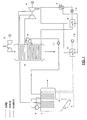
- example 1 is the application of the process to a MSW incinerating plant working with a pure steam cycle.
- the parameters of the steam cycle are typical values for this type of plants, except the maximum pressure in the furnace-boiler (1) which in this case is not limited by the final wetness in the expansion and, therefore, has been raised to an optimum value of 105 bar abs.
- feedwater is heated until saturation, vaporized and superheated at the maximum process pressure.
- the additional saturated steam obtained is mixed with that exhausted from the high-pressure body of steam turbine (6), which in this case is at a very similar temperature, and is reheated by the energy corresponding to the heat yield of higher temperature of gas turbine (5) exhaust gases before it is admitted to the low-pressure body of turbine (6).
- the combustion gases of gas turbine (5) after the aforementioned reheating and vaporization, are used for heating the liquid from the temperature of preheating (carried out by means of an extraction from low-pressure steam turbine (6)) to the inlet temperature to incineration furnace-boiler (1).
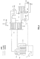
- Example 2 shows an application of the process to a MSW incinerating plant working with a vapor mixture of water and TF.
- This option has all the advantages of the vapor reheating using the exhaust waste heat of a gas turbine (16) plus those offered by the use of a vapor mixture of thermal fluid (TF) and water.
- the schematic includes the partial heating of feedwater until saturation at the maximum pressure, the vaporization at this pressure and the superheating of the vapor to the temperature of 400°C in furnace-boiler (13), in exactly the same way and under identical conditions as in example 1, except the small percentage of TF (4%) that accompanies the water, without hardly any practical incidence, which therefore has been neglected for the sake of simplicity of calculation, and the vapor is considered pure steam.
- the heat recovery from the exhaust gases of turbine (16) is carried out in the following way:
- the waste heat corresponding to the non-isothermal condensation of TF is used with very little exergy loss for the primary heating of combustion air and the primary heating of condensates (TF plus water).
- the energy of higher thermal level of this recovery is used for vaporizing a part of water at low pressure which is introduced into the expanding flow in turbine (19) through a partial admission.
- Tables 1 and 2 show the basic results of the thermal balances for application examples 1 and 2, respectively.
- Figures 1 and 2 are the basic thermal schematics of the plant for application examples 1 and 2, respectively, which include the following elements:
Landscapes
- Engineering & Computer Science (AREA)
- Chemical & Material Sciences (AREA)
- Combustion & Propulsion (AREA)
- Mechanical Engineering (AREA)
- General Engineering & Computer Science (AREA)
- Engine Equipment That Uses Special Cycles (AREA)
Applications Claiming Priority (3)
| Application Number | Priority Date | Filing Date | Title |
|---|---|---|---|
| ES9300930A ES2116136B1 (es) | 1993-05-03 | 1993-05-03 | Procedimiento de mejora de la combinacion entre una turbina de gas y un ciclo de vapor con otra fuente no fosil de energia primaria. |
| ES9300093 | 1993-05-03 | ||
| PCT/ES1994/000017 WO1994025739A1 (es) | 1993-05-03 | 1994-02-18 | Procedimiento de mejora de la combinacion entre une turbina de gas y un ciclo de vapor con otra fuente no fosil de energia primaria |
Publications (1)
| Publication Number | Publication Date |
|---|---|
| EP0664377A1 true EP0664377A1 (de) | 1995-07-26 |
Family
ID=8281672
Family Applications (1)
| Application Number | Title | Priority Date | Filing Date |
|---|---|---|---|
| EP94907572A Withdrawn EP0664377A1 (de) | 1993-05-03 | 1994-02-18 | Verfahren zur verbesserung einer dampfturbine und dampfkreislauf kombiniertensystems mit einer fosilen primärenergiequelle |
Country Status (3)
| Country | Link |
|---|---|
| EP (1) | EP0664377A1 (de) |
| ES (1) | ES2116136B1 (de) |
| WO (1) | WO1994025739A1 (de) |
Cited By (2)
| Publication number | Priority date | Publication date | Assignee | Title |
|---|---|---|---|---|
| WO1997014887A1 (de) * | 1995-10-17 | 1997-04-24 | Siemens Aktiengesellschaft | Verfahren zur erzeugung von energie und kraftwerksanlage zur durchführung des verfahrens |
| WO2010057279A1 (en) * | 2008-11-24 | 2010-05-27 | Ribeiro Sergio Vieira Guerreir | High efficiency waste to energy power plants combining municipal solid waste and natural gas |
Family Cites Families (6)
| Publication number | Priority date | Publication date | Assignee | Title |
|---|---|---|---|---|
| ES2005135A6 (es) * | 1987-04-08 | 1989-03-01 | Carnot Sa | Ciclo termico con fluido de trabajo mezcla |
| NL8701573A (nl) * | 1987-07-03 | 1989-02-01 | Prometheus Energy Systems | Werkwijze en inrichting voor het opwekken van elektrische en/of mechanische energie uit tenminste een laagwaardige brandstof. |
| ES2006059A6 (es) * | 1988-01-21 | 1989-04-01 | Sener Ing & Sist | Sistemas para la produccion de vapor de agua a alta presion y temperatura. |
| DE4101064A1 (de) * | 1991-01-16 | 1992-07-23 | Radebeul Energie Umwelt | Verfahren zum betreiben eines kraftwerkes |
| DE4103228A1 (de) * | 1991-02-02 | 1992-08-06 | Radebeul Energie Umwelt | Verfahren zum betreiben von kraftwerken |
| DE4117191C2 (de) * | 1991-05-25 | 1994-11-24 | Saarbergwerke Ag | Kombinierte Gas-Dampfkraftanlage zur Erzeugung von Energie |
-
1993
- 1993-05-03 ES ES9300930A patent/ES2116136B1/es not_active Expired - Fee Related
-
1994
- 1994-02-18 WO PCT/ES1994/000017 patent/WO1994025739A1/es not_active Ceased
- 1994-02-18 EP EP94907572A patent/EP0664377A1/de not_active Withdrawn
Non-Patent Citations (1)
| Title |
|---|
| See references of WO9425739A1 * |
Cited By (2)
| Publication number | Priority date | Publication date | Assignee | Title |
|---|---|---|---|---|
| WO1997014887A1 (de) * | 1995-10-17 | 1997-04-24 | Siemens Aktiengesellschaft | Verfahren zur erzeugung von energie und kraftwerksanlage zur durchführung des verfahrens |
| WO2010057279A1 (en) * | 2008-11-24 | 2010-05-27 | Ribeiro Sergio Vieira Guerreir | High efficiency waste to energy power plants combining municipal solid waste and natural gas |
Also Published As
| Publication number | Publication date |
|---|---|
| ES2116136B1 (es) | 1998-12-16 |
| ES2116136A1 (es) | 1998-07-01 |
| WO1994025739A1 (es) | 1994-11-10 |
Similar Documents
| Publication | Publication Date | Title |
|---|---|---|
| US5822990A (en) | Converting heat into useful energy using separate closed loops | |
| KR100628597B1 (ko) | 가스 터빈 복합 사이클 발전장치로 유입되는 공기의 냉각 방법 및 변형 보토밍 사이클 | |
| US3950949A (en) | Method of converting low-grade heat energy to useful mechanical power | |
| AU2008349706B2 (en) | Method for operating a thermodynamic circuit, as well as a thermodynamic circuit | |
| CA1309871C (en) | Direct fired power cycle | |
| US6694740B2 (en) | Method and system for a thermodynamic process for producing usable energy | |
| US6347520B1 (en) | Method for Kalina combined cycle power plant with district heating capability | |
| US5251432A (en) | Method for operating a gas and steam turbine plant | |
| US8839621B2 (en) | Hybrid power plant | |
| US4838027A (en) | Power cycle having a working fluid comprising a mixture of substances | |
| US20060010868A1 (en) | Method of converting energy | |
| US6244033B1 (en) | Process for generating electric power | |
| AU2005233321A1 (en) | Method and device for carrying out a thermodynamic cyclic process | |
| US4729226A (en) | Process for mechanical power generation | |
| US4896496A (en) | Single pressure steam bottoming cycle for gas turbines combined cycle | |
| US5715682A (en) | Combined-cycle power generation system using waste matter as fuel | |
| RU2230921C2 (ru) | Способ работы парогазовой электростанции на комбинированном топливе (твердом с газообразным или жидким) и парогазовая установка для его реализации | |
| JP3905967B2 (ja) | 発電・給湯システム | |
| RU2079672C1 (ru) | Способ регенерации теплоты пара в парогазовых циклах | |
| RU101090U1 (ru) | Энергетическая надстроечная парогазовая установка (варианты) | |
| EP0664377A1 (de) | Verfahren zur verbesserung einer dampfturbine und dampfkreislauf kombiniertensystems mit einer fosilen primärenergiequelle | |
| JP3017937B2 (ja) | 水素燃焼タービンプラント | |
| CN102105656B (zh) | 混合发电装置 | |
| EP0652352A1 (de) | Verwertung des abgases einer gasturbinenanlage zur zweiten zwischenüberhitzung der hauptströmung eines dampfkreislaufes | |
| JPS58167811A (ja) | 蒸気タ−ビン)ガスタ−ビン動作サイクルプラント |
Legal Events
| Date | Code | Title | Description |
|---|---|---|---|
| PUAI | Public reference made under article 153(3) epc to a published international application that has entered the european phase |
Free format text: ORIGINAL CODE: 0009012 |
|
| AK | Designated contracting states |
Kind code of ref document: A1 Designated state(s): DE DK ES FR GB |
|
| 17P | Request for examination filed |
Effective date: 19950810 |
|
| STAA | Information on the status of an ep patent application or granted ep patent |
Free format text: STATUS: THE APPLICATION IS DEEMED TO BE WITHDRAWN |
|
| 18D | Application deemed to be withdrawn |
Effective date: 19970902 |