EP0664399B1 - Ensemble de pompage - Google Patents
Ensemble de pompage Download PDFInfo
- Publication number
- EP0664399B1 EP0664399B1 EP95100761A EP95100761A EP0664399B1 EP 0664399 B1 EP0664399 B1 EP 0664399B1 EP 95100761 A EP95100761 A EP 95100761A EP 95100761 A EP95100761 A EP 95100761A EP 0664399 B1 EP0664399 B1 EP 0664399B1
- Authority
- EP
- European Patent Office
- Prior art keywords
- unit
- pump
- operating
- control
- pump unit
- Prior art date
- Legal status (The legal status is an assumption and is not a legal conclusion. Google has not performed a legal analysis and makes no representation as to the accuracy of the status listed.)
- Expired - Lifetime
Links
- 238000010438 heat treatment Methods 0.000 claims description 5
- 238000004891 communication Methods 0.000 claims description 3
- 230000001105 regulatory effect Effects 0.000 claims description 3
- 230000005540 biological transmission Effects 0.000 description 10
- 238000013461 design Methods 0.000 description 3
- 238000010276 construction Methods 0.000 description 2
- 238000009434 installation Methods 0.000 description 2
- 238000012423 maintenance Methods 0.000 description 2
- 230000008054 signal transmission Effects 0.000 description 2
- 238000013475 authorization Methods 0.000 description 1
- 238000010586 diagram Methods 0.000 description 1
- 230000007257 malfunction Effects 0.000 description 1
- 238000012545 processing Methods 0.000 description 1
- 238000011144 upstream manufacturing Methods 0.000 description 1
Images
Classifications
-
- F—MECHANICAL ENGINEERING; LIGHTING; HEATING; WEAPONS; BLASTING
- F04—POSITIVE - DISPLACEMENT MACHINES FOR LIQUIDS; PUMPS FOR LIQUIDS OR ELASTIC FLUIDS
- F04D—NON-POSITIVE-DISPLACEMENT PUMPS
- F04D15/00—Control, e.g. regulation, of pumps, pumping installations or systems
- F04D15/0066—Control, e.g. regulation, of pumps, pumping installations or systems by changing the speed, e.g. of the driving engine
-
- G—PHYSICS
- G08—SIGNALLING
- G08C—TRANSMISSION SYSTEMS FOR MEASURED VALUES, CONTROL OR SIMILAR SIGNALS
- G08C23/00—Non-electrical signal transmission systems, e.g. optical systems
- G08C23/04—Non-electrical signal transmission systems, e.g. optical systems using light waves, e.g. infrared
-
- G—PHYSICS
- G08—SIGNALLING
- G08C—TRANSMISSION SYSTEMS FOR MEASURED VALUES, CONTROL OR SIMILAR SIGNALS
- G08C2201/00—Transmission systems of control signals via wireless link
- G08C2201/50—Receiving or transmitting feedback, e.g. replies, status updates, acknowledgements, from the controlled devices
Definitions
- the invention relates to a pump unit with the features specified in the preamble of claim 1.
- Pump units of the type mentioned at the outset are known in numerous designs; today, they are used, for example, as heating circulation pumps.
- the miniaturization in the electronic field has made it possible for electronic speed controllers to be integrated in the pump unit, which enable the pump to be operated in characteristic maps.
- electronic control is assigned to the speed controller.
- the desired operating points of the pump unit can be preset via an electronic control integrated in the pump unit via a switch accessible from the outside on the pump housing. It has proven useful to specify various control variables or control characteristics, each of which enables pump operation to be carried out as required and which can be preselected by means of appropriate switches on the outside of the pump unit. Depending on the switch position, the pump set can be operated with different control modes, depending on the requirement profile.
- the object of the present invention is to design a generic pump unit with structurally simple means which are inexpensive to produce and operate reliably in such a way that the aforementioned disadvantages can be avoided as far as possible or at least largely.
- the invention therefore provides a wireless mobile remote control for the pump unit, with which at least a desired control variable can be set. In practice, this has considerable advantages.
- the unit can also be arranged in places that are difficult to access without endangering operability. Costly and fault-prone wiring is not necessary. With appropriate handling of the transmitter, incorrect operation can largely be ruled out by the transmitter being accessible only to the specialist and being kept under lock and key. With appropriate design of the transmission type (radio), it is even possible to control or operate different pump sets from a central location without additional wiring being required.
- connection module for receiving a measuring device for the electrical or hydraulic operating variables of the motor or pumps to the pump unit and releasably on this connecting module from the outside a further registration device for storing and displaying operating variables to be releasably attached and to provide a wireless transmission of data between the connection module and the further releasable module, but here the wireless transmission only serves for electrical safety, otherwise this pump unit has all the disadvantages that were initially explained with reference to the prior art, of which the present invention is based on.
- the pump unit not only has a receiver, but also a transmitter, since then not only transmits manipulated variables to the unit, but also wirelessly operating data of the unit to an external receiver can be transmitted. It goes without saying that it is expedient to integrate the external transmitter and the external receiver in a common device with which the pump unit can be operated and checked. In this way, an external operating and control unit of the pump unit is formed.
- Such an operating and control unit expediently has a display for displaying the transmitted operating data, so that the operator can check the corresponding pump unit at a glance and also immediately receives repercussions about the changes made to his settings.
- Such displays can also be found on modern pump units on the unit itself.
- the mobile structural unit (control unit) provided according to the invention as an operating and control unit then has the advantage that a corresponding display on the pump can be omitted.
- the operating and control unit can preferably also have a printing or storage unit for recording operating data and an interface for connecting a printer or other data memory.
- a printing or storage unit for recording operating data and an interface for connecting a printer or other data memory.
- Such a device is particularly useful if data is to be recorded reliably over a long period of time, as is required, for example, when searching for faults in the system which only occur sporadically is.
- operating and control units according to the invention are issued with different access authorizations, so that the operator of a system can, for example, only make the settings on his operating and control unit that have previously been released by the expert while the Operating and control unit of the maintenance personnel all settings can be carried out.
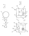
- an electric motor-driven pump unit 1 is shown, as it can be used for example in heating systems as a circulation pump.
- the control electronics and the speed controller in the form of a frequency converter - these components are usually arranged in the terminal box of the unit - are designated by 2.
- the reference number 3 identifies the transmission and reception electronics upstream of the control electronics, insofar as it is arranged on the aggregate side.
- the transmission and reception electronics communicating with the transmission and reception electronics 3 of the pump unit 1 is arranged within a mobile assembly 4 (control unit) in the form of an operating and control unit.
- the arrows 5 and 6 symbolize the wireless data flow from the operating and control unit 4 to the pump unit 1 and vice versa.
- the pump-side transmitting and receiving part 3 has an infrared transmitter 7 and an infrared receiver 8, to which an infrared transmitter 9 and an infrared receiver 10 are assigned in the operating part 4.
- the control unit 4 has a numerical input field 11, via which number combinations can be entered, to which corresponding control commands are assigned, specifically via the converter module, designated 12 in the transmitting and receiving electronics 3, which converts the output signal of the IR receiver 8 into a for the Control electronics 2 understandable signal converts.
- the signal connection between the transmitting and receiving electronics 3 and the control electronics 2 is identified by 13.
- signals can be sent to the infrared receiver 8 by means of corresponding numerical inputs via the input field 11 by means of the infrared transmitter 9 the converter module 12 are decrypted or converted into a signal with which characteristic curves can be selected directly in the control electronics 2.
- a control unit can also be provided in the operating part 4, with which a data protocol can be printed out.
- the control unit has a memory module 16 connected in parallel with the display 15, which stores the received data, not only the current value, but also the operating state over time. This data can be queried via an interface 17 or processed in an electronic data processing system.
- a signal connection 18 is provided within the control unit 4, which also supplies the output data of the converter module 12 directly to the infrared transmitter and thus to the control unit. In this way, the signal transmission 5 can be controlled, and the corresponding can also be provided for the signal transmission 6.
Landscapes
- Engineering & Computer Science (AREA)
- Mechanical Engineering (AREA)
- General Engineering & Computer Science (AREA)
- Physics & Mathematics (AREA)
- General Physics & Mathematics (AREA)
- Control Of Positive-Displacement Pumps (AREA)
- Eye Examination Apparatus (AREA)
Claims (6)
- Groupe moto-pompe pour une installation de chauffage, comportant une pompe centrifuge, un moteur électrique entraînant cette dernière, un variateur de vitesse de rotation (2) intégré dans le groupe et une commande électronique (2) intégrée dans le groupe, ainsi qu'un dispositif de régulation qui est associé au variateur de vitesse de rotation (2) et dont les grandeurs réglées peuvent être choisies au moyen de la commande (2), caractérisé en ce que la commande (2) comporte un récepteur destiné à recevoir des signaux de réglage en vue de l'ajustement d'au moins une grandeur réglée souhaitée, ces signaux étant transmis sans fil par un émetteur externe (9), qui est réalisé sous la forme d'un module mobile (4) et qui constitue une unité externe de commande (4) du groupe moto-pompe (1).
- Groupe moto-pompe selon la revendication 1, caractérisé en ce que le groupe moto-pompe (1) comporte un émetteur (7), à l'aide duquel des données de fonctionnement du groupe peuvent être communiquées, sans fil, à un récepteur externe (10).
- Groupe moto-pompe selon la revendication 1 ou 2, caractérisé en ce que l'émetteur externe (9) et le récepteur externe (10) sont agencés en un module mobile (4), qui constitue une unité externe de commande et de contrôle (4) du groupe moto-pompe (1).
- Groupe moto-pompe selon l'une des revendications précédentes, caractérisé en ce que l'unité de commande et de contrôle (4) comporte un afficheur (15) pour l'affichage des données de fonctionnement communiquées.
- Groupe moto-pompe selon l'une des revendications précédentes, caractérisé en ce que l'unité de commande et de contrôle (4) comporte une unité d'impression ou autre unité d'enregistrement (16), pour l'enregistrement de données de fonctionnement, et/ou une interface (17) pour le raccordement d'une imprimante ou d'un autre enregistreur de données.
- Groupe moto-pompe selon l'une des revendications précédentes, caractérisé en ce que la communication entre émetteur (9; 7) et récepteur (8; 10) se fait au moyen de signaux optiques (5, 6), de préférence dans le domaine des infrarouges.
Applications Claiming Priority (2)
| Application Number | Priority Date | Filing Date | Title |
|---|---|---|---|
| DE9400955U | 1994-01-21 | ||
| DE9400955U DE9400955U1 (de) | 1994-01-21 | 1994-01-21 | Pumpenaggregat |
Publications (2)
| Publication Number | Publication Date |
|---|---|
| EP0664399A1 EP0664399A1 (fr) | 1995-07-26 |
| EP0664399B1 true EP0664399B1 (fr) | 1997-07-16 |
Family
ID=6903489
Family Applications (1)
| Application Number | Title | Priority Date | Filing Date |
|---|---|---|---|
| EP95100761A Expired - Lifetime EP0664399B1 (fr) | 1994-01-21 | 1995-01-20 | Ensemble de pompage |
Country Status (2)
| Country | Link |
|---|---|
| EP (1) | EP0664399B1 (fr) |
| DE (2) | DE9400955U1 (fr) |
Cited By (1)
| Publication number | Priority date | Publication date | Assignee | Title |
|---|---|---|---|---|
| DE102007011204A1 (de) * | 2006-10-17 | 2008-04-24 | Wilo Ag | Verfahren zur Übertragung von Daten und Datenübertragungsvorrichtung zur Fernsteuerung und/oder Fernabfrage |
Families Citing this family (13)
| Publication number | Priority date | Publication date | Assignee | Title |
|---|---|---|---|---|
| DE19511170A1 (de) * | 1995-03-28 | 1996-10-02 | Wilo Gmbh | Doppelpumpe mit übergeordneter Steuerung |
| DE19605132C2 (de) * | 1996-02-13 | 1998-02-05 | Kostal Leopold Gmbh & Co Kg | Verfahren zum Kommunikationsaufbau zwischen einer Fernwirkeinrichtung und zugeordneten Aggregaten |
| EP0866228A3 (fr) * | 1997-03-18 | 2000-12-13 | Grundfos A/S | Unité de pompage |
| DE19959877B4 (de) | 1999-12-13 | 2008-06-19 | Sew-Eurodrive Gmbh & Co. Kg | Anlage mit Kasten mit hoher Schutzart und ein Verfahren zum Fernbedienen dieser Anlage |
| DE10018866A1 (de) | 2000-04-14 | 2001-10-25 | Grundfos As | Pumpenaggregat |
| DE10163987A1 (de) * | 2001-12-24 | 2003-07-10 | Grundfos As | Verfahren zum Steuern einer drehzahlregelbaren Heizungsumwälzpumpe |
| DE20206267U1 (de) * | 2002-04-20 | 2003-08-28 | Leybold Vakuum GmbH, 50968 Köln | Vakuumpumpe |
| EP1452739B1 (fr) * | 2003-02-26 | 2014-09-17 | Grundfos A/S | Interface pour dispositif de commande d'une pompe |
| DE602004005154T2 (de) † | 2004-03-15 | 2007-11-08 | Varian S.P.A., Leini | Vakuumpumpenanlage |
| DE102007017445C5 (de) * | 2007-04-02 | 2015-08-27 | Alfred Kärcher Gmbh & Co. Kg | Flüssigkeitspumpe |
| DE102007016385A1 (de) * | 2007-04-03 | 2008-10-09 | Knf Neuberger Gmbh | Pumpstand |
| DE102011056865B3 (de) * | 2011-12-22 | 2013-01-03 | Az Pokorny S.R.O. | Einrichtung zur Steuerung einer Heizungsumwälzpumpe und Steuerungsverfahren |
| CN212717231U (zh) * | 2020-07-10 | 2021-03-16 | 谢永祺 | 遥控泵 |
Family Cites Families (5)
| Publication number | Priority date | Publication date | Assignee | Title |
|---|---|---|---|---|
| FR2045586A1 (fr) * | 1969-06-03 | 1971-03-05 | Materiel Telephonique | |
| DE3408965C2 (de) * | 1984-03-12 | 1986-11-13 | Waldsee Electronic GmbH, 7967 Bad Waldsee | Vorrichtung zur Drehzahlmessung an Pumpen |
| DE3710514A1 (de) * | 1987-03-30 | 1988-10-20 | Manfred Viesel | Dickstoffpumpe, insbesondere fuer moertel und putze |
| IT8783350A0 (it) * | 1987-04-13 | 1987-04-13 | Cerit Spa | Sistema di regolazione continua del flusso d'acqua in vasche per idromassaggio |
| DE3828207A1 (de) * | 1988-08-19 | 1990-02-22 | Oplaender Wilo Werk Gmbh | Diagnosestecker |
-
1994
- 1994-01-21 DE DE9400955U patent/DE9400955U1/de not_active Expired - Lifetime
-
1995
- 1995-01-20 DE DE59500367T patent/DE59500367D1/de not_active Expired - Lifetime
- 1995-01-20 EP EP95100761A patent/EP0664399B1/fr not_active Expired - Lifetime
Cited By (1)
| Publication number | Priority date | Publication date | Assignee | Title |
|---|---|---|---|---|
| DE102007011204A1 (de) * | 2006-10-17 | 2008-04-24 | Wilo Ag | Verfahren zur Übertragung von Daten und Datenübertragungsvorrichtung zur Fernsteuerung und/oder Fernabfrage |
Also Published As
| Publication number | Publication date |
|---|---|
| DE9400955U1 (de) | 1994-03-03 |
| EP0664399A1 (fr) | 1995-07-26 |
| DE59500367D1 (de) | 1997-08-21 |
Similar Documents
| Publication | Publication Date | Title |
|---|---|---|
| EP0664399B1 (fr) | Ensemble de pompage | |
| DE3614744C2 (de) | Vorrichtung zum Steuern einer Rotationsdruckmaschine | |
| EP0814397B1 (fr) | Ordinateur portable de bord avec unités de commande pour machines de travail | |
| EP1926069B1 (fr) | Télécommande radio | |
| EP3600780B1 (fr) | Procédé de détection d'au moins une grandeur caractéristique d'au moins un outil | |
| DE102004051145A1 (de) | Sensorsystem für eine spanabhebende Werkzeugmaschine | |
| DE69202195T2 (de) | Funkfeinsteuerungseinrichtung für eine bewegliche motorisierte Maschine. | |
| WO2000017720A1 (fr) | Outil de traitement et dispositif de traitement pour façonner une piece a travailler | |
| EP3268823B1 (fr) | Dispositif et procédé de commande de tables réglables en hauteur | |
| EP1497558A1 (fr) | Pompe a vide | |
| DE60029018T2 (de) | Ladegeschirr | |
| DE102007060609A1 (de) | Verfahren zur Anzeige einer Information | |
| DE102012220956A1 (de) | Erfassungssystem für ein automatisiertes Fahrzeug | |
| EP1417875B1 (fr) | Commutateur configurable librement pour véhicules agricoles et communaux et leurs accessoires | |
| DE10041109B4 (de) | System und Verfahren zum Bedienen und Beobachten insbesondere eines Automatisierungssystems mit mobiler Bedienvorrichtung | |
| EP1000810B1 (fr) | Système d'ordinateur pour véhicule | |
| DE102005024883A1 (de) | Flurförderzeug | |
| WO2015000918A1 (fr) | Dispositif de communication sécurisé pour un véhicule et système de véhicule | |
| DE102014214067B4 (de) | Bedienteil | |
| DE102017206554A1 (de) | Werkzeugmaschine, insbesondere tragbare Werkzeugmaschine | |
| DE102014209258A1 (de) | Funksteuersystem für eine Maschine, insbesondere für einen Kran oder ein Hebezeug | |
| EP3392084A1 (fr) | Remorque de véhicule utilitaire | |
| EP1316001B1 (fr) | Systeme de maintenance destine a des appareils de commande de transmissions hydrostatiques | |
| DE19948272A1 (de) | Automatisierungssystem mit Controller | |
| EP3835897B1 (fr) | Commande d'appareil chauffant à gaz pour un appareil chauffant à gaz |
Legal Events
| Date | Code | Title | Description |
|---|---|---|---|
| PUAI | Public reference made under article 153(3) epc to a published international application that has entered the european phase |
Free format text: ORIGINAL CODE: 0009012 |
|
| AK | Designated contracting states |
Kind code of ref document: A1 Designated state(s): DE FR GB IT |
|
| 17P | Request for examination filed |
Effective date: 19950824 |
|
| GRAG | Despatch of communication of intention to grant |
Free format text: ORIGINAL CODE: EPIDOS AGRA |
|
| GRAH | Despatch of communication of intention to grant a patent |
Free format text: ORIGINAL CODE: EPIDOS IGRA |
|
| 17Q | First examination report despatched |
Effective date: 19961202 |
|
| GRAH | Despatch of communication of intention to grant a patent |
Free format text: ORIGINAL CODE: EPIDOS IGRA |
|
| GRAA | (expected) grant |
Free format text: ORIGINAL CODE: 0009210 |
|
| AK | Designated contracting states |
Kind code of ref document: B1 Designated state(s): DE FR GB IT |
|
| REF | Corresponds to: |
Ref document number: 59500367 Country of ref document: DE Date of ref document: 19970821 |
|
| ITF | It: translation for a ep patent filed | ||
| GBT | Gb: translation of ep patent filed (gb section 77(6)(a)/1977) |
Effective date: 19970925 |
|
| ET | Fr: translation filed | ||
| PLBQ | Unpublished change to opponent data |
Free format text: ORIGINAL CODE: EPIDOS OPPO |
|
| PLBI | Opposition filed |
Free format text: ORIGINAL CODE: 0009260 |
|
| PLBF | Reply of patent proprietor to notice(s) of opposition |
Free format text: ORIGINAL CODE: EPIDOS OBSO |
|
| 26 | Opposition filed |
Opponent name: WILO GMBH Effective date: 19980415 |
|
| PLBF | Reply of patent proprietor to notice(s) of opposition |
Free format text: ORIGINAL CODE: EPIDOS OBSO |
|
| PLBF | Reply of patent proprietor to notice(s) of opposition |
Free format text: ORIGINAL CODE: EPIDOS OBSO |
|
| PLBL | Opposition procedure terminated |
Free format text: ORIGINAL CODE: EPIDOS OPPC |
|
| PLBM | Termination of opposition procedure: date of legal effect published |
Free format text: ORIGINAL CODE: 0009276 |
|
| STAA | Information on the status of an ep patent application or granted ep patent |
Free format text: STATUS: OPPOSITION PROCEDURE CLOSED |
|
| 27C | Opposition proceedings terminated |
Effective date: 19990321 |
|
| REG | Reference to a national code |
Ref country code: GB Ref legal event code: IF02 |
|
| PG25 | Lapsed in a contracting state [announced via postgrant information from national office to epo] |
Ref country code: IT Free format text: LAPSE BECAUSE OF NON-PAYMENT OF DUE FEES Effective date: 20050120 |
|
| PGRI | Patent reinstated in contracting state [announced from national office to epo] |
Ref country code: IT Effective date: 20091201 |
|
| PGFP | Annual fee paid to national office [announced via postgrant information from national office to epo] |
Ref country code: FR Payment date: 20131122 Year of fee payment: 20 Ref country code: GB Payment date: 20131219 Year of fee payment: 20 |
|
| PGFP | Annual fee paid to national office [announced via postgrant information from national office to epo] |
Ref country code: DE Payment date: 20140225 Year of fee payment: 20 |
|
| PGFP | Annual fee paid to national office [announced via postgrant information from national office to epo] |
Ref country code: IT Payment date: 20131126 Year of fee payment: 20 |
|
| REG | Reference to a national code |
Ref country code: DE Ref legal event code: R071 Ref document number: 59500367 Country of ref document: DE |
|
| REG | Reference to a national code |
Ref country code: GB Ref legal event code: PE20 Expiry date: 20150119 |
|
| PG25 | Lapsed in a contracting state [announced via postgrant information from national office to epo] |
Ref country code: GB Free format text: LAPSE BECAUSE OF EXPIRATION OF PROTECTION Effective date: 20150119 |