EP0664436A2 - Dispositif et méthode pour mesurer le pincement de roues - Google Patents
Dispositif et méthode pour mesurer le pincement de roues Download PDFInfo
- Publication number
- EP0664436A2 EP0664436A2 EP95850014A EP95850014A EP0664436A2 EP 0664436 A2 EP0664436 A2 EP 0664436A2 EP 95850014 A EP95850014 A EP 95850014A EP 95850014 A EP95850014 A EP 95850014A EP 0664436 A2 EP0664436 A2 EP 0664436A2
- Authority
- EP
- European Patent Office
- Prior art keywords
- sighting
- wheel
- scales
- light beam
- measuring
- Prior art date
- Legal status (The legal status is an assumption and is not a legal conclusion. Google has not performed a legal analysis and makes no representation as to the accuracy of the status listed.)
- Granted
Links
Images

Classifications
-
- G—PHYSICS
- G01—MEASURING; TESTING
- G01B—MEASURING LENGTH, THICKNESS OR SIMILAR LINEAR DIMENSIONS; MEASURING ANGLES; MEASURING AREAS; MEASURING IRREGULARITIES OF SURFACES OR CONTOURS
- G01B11/00—Measuring arrangements characterised by the use of optical techniques
- G01B11/26—Measuring arrangements characterised by the use of optical techniques for measuring angles or tapers; for testing the alignment of axes
- G01B11/275—Measuring arrangements characterised by the use of optical techniques for measuring angles or tapers; for testing the alignment of axes for testing wheel alignment
-
- G—PHYSICS
- G01—MEASURING; TESTING
- G01B—MEASURING LENGTH, THICKNESS OR SIMILAR LINEAR DIMENSIONS; MEASURING ANGLES; MEASURING AREAS; MEASURING IRREGULARITIES OF SURFACES OR CONTOURS
- G01B2210/00—Aspects not specifically covered by any group under G01B, e.g. of wheel alignment, caliper-like sensors
- G01B2210/10—Wheel alignment
- G01B2210/22—Wheels in a state of motion supported on rollers, rotating platform or other structure substantially capable of only one degree of rotational freedom
-
- G—PHYSICS
- G01—MEASURING; TESTING
- G01B—MEASURING LENGTH, THICKNESS OR SIMILAR LINEAR DIMENSIONS; MEASURING ANGLES; MEASURING AREAS; MEASURING IRREGULARITIES OF SURFACES OR CONTOURS
- G01B2210/00—Aspects not specifically covered by any group under G01B, e.g. of wheel alignment, caliper-like sensors
- G01B2210/10—Wheel alignment
- G01B2210/24—Specially developed for using with trucks or other heavy-duty vehicles
-
- G—PHYSICS
- G01—MEASURING; TESTING
- G01B—MEASURING LENGTH, THICKNESS OR SIMILAR LINEAR DIMENSIONS; MEASURING ANGLES; MEASURING AREAS; MEASURING IRREGULARITIES OF SURFACES OR CONTOURS
- G01B2210/00—Aspects not specifically covered by any group under G01B, e.g. of wheel alignment, caliper-like sensors
- G01B2210/10—Wheel alignment
- G01B2210/28—Beam projector and related sensors, camera, inclinometer or other active sensing or projecting device
- G01B2210/283—Beam projectors and related sensors
-
- G—PHYSICS
- G01—MEASURING; TESTING
- G01B—MEASURING LENGTH, THICKNESS OR SIMILAR LINEAR DIMENSIONS; MEASURING ANGLES; MEASURING AREAS; MEASURING IRREGULARITIES OF SURFACES OR CONTOURS
- G01B2210/00—Aspects not specifically covered by any group under G01B, e.g. of wheel alignment, caliper-like sensors
- G01B2210/10—Wheel alignment
- G01B2210/30—Reference markings, reflector, scale or other passive device
- G01B2210/303—Reference markings, reflector, scale or other passive device fixed to the ground or to the measuring station
Definitions
- This invention is related to a device, a set up and a method for the measuring of wheel angles at vehicles for the checking and adjustment thereof.
- a wheel measuring device that includes light beam projection means or sighting means, possibly in the shape of video cameras, that unyieldingly and unturnably are mounted on the wheels.
- the light beam projection means include a light source or light sources that can emit light beams in two opposite directions. If instead a sighting device is used this is made so that it can be sighted with in two opposed directions.
- the invention makes use of measuring scales on which the light beams project or on which readings are taken by means of sighting devices.
- the sighting devices may consist of video cameras either two mounted together and with opposing viewing directions or a single camera that is made to look in two directions by means of mirrors. By using different filters for the different directions the different reading may be recognized.
- position or location indicators can be used providing the camera with fixed points the lateral positions of which relative the center plane of the camera can be obtained by electronic picture processing.
- location indicators can be very simple means, for instance a frame painted on the floor, Light emitting diodes recessed into the floor or mounted on specific points on the vehicle. for this latter case no filters are necessary since the diodes may have different colors recognizable by the camera or rather the electronic processing connected to it or them.
- Another object of the invention is to provide a measuring method that will allow quick measuring with high precision even in untrained hands. This is in accordance with the invention achieved by using the invented device described above in the manner set forth below.
- the light source in the invented device transmitting light in two diametrically opposite directions eliminates the need of adjustment of the light sources in relation to the wheels.
- the reason for this is that if the wheel is skew or for some other reason the emitted beams are not exactly perpendicular to the rotation axis of the wheel this will result in the opposed beams giving different readings on the scale or scales as the wheel is rotated, but the actual toe-in angle of the wheel corresponds to the middle value of the two readings, that is a point precisely between the two readings on each scale.
- These points precisely in the middle between the readings on each scale correspond to the readings that would have been obtained if the lasers had been adjusted to be precisely perpendicular to the wheel axis, however the exactness will be improved with the invention and the measurement will be obtained quicker.
- the most important angle is the toe-in and it is also the angle that most easily is upset. This angle can be measured with only two scales on each side of the vehicle if these are on the same horizontal level, since in this way the plane of the measuring scales will be parallel to the plane in which the toe-in angle lies.
- the wheels are rotated on their own axles in order to obtain the two readings. This can be done by jacking up the vehicle enabling the wheels to rotate freely, this is however less desirable since the wheel angles then often change.
- the wheels are so arranged that they can be rotated while still supporting the vehicle, this can for instance be achieved by placing them on rollers or endless bands supported on rollers or other means.
- the laser device is provided with an additional lockable angular adjustment means between the light beam source and its wheel mounting bracket in such a way that the light beams can be angled relative the rotational plane of the wheel.
- the light beam source is further provided with a spirit level so arranged that its zero or adjusted position gives the light beam and its source a vertical direction.
- the light source By positioning the light source vertically and then locking the adjustment means the light source will have an angle relative the rotational plane of the wheel that is the same as the camber angle of the wheel.
- the wheel is then turned over a quarter of a turn or a right angle so that the light beams are projected on a front and rear scale giving first readings or scale values. If the wheel is turned forwards, the scales get a second readings. The difference between the two readings are related to the camber of the wheel. For each scale the camber angle will move one reading to the right and one to the left so that the distance between the readings correspond to the double camber angle.
- the true camber in millimeter per meter can therefor be calculated as the difference between the front scale readings plus the difference between the rear scale readings divided by the double distance in meter between the scales. This also means that the exact location of the wheel is unimportant for the exact calculation of the camber angle. Since this camber angle in millimeters per meter actually is the tangent of the camber angle the camber angle in degrees can be obtained through the arctan-function.
- the toe in angle can be measured or rather be evaluated simultaneously with the above camber evaluation by taking the readings on the scales given by rotating the wheel over three quarters of a turn. As in the previously described methods the toe-in is given by the mean or middle value between the readings on each scale.
- the cameras can instead of scales use a framing for instance painted on the floor or ground together with the contour of the vehicle or simple additional sighting means fastened to the vehicle as a base for the calculations. Still however it is the sighting in two directions that renders adjustment of the sighting device on the wheel unnecessary (unless the camber angle is to be measured by means of a spirit level)
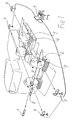
- Fig. 1 depicts the measuring of front wheel angles in a first embodiment
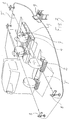
- fig. 2 front wheel measuring in a second embodiment
- fig 3 the measuring of the angles at rear wheels
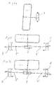
- fig 4 schematically a measuring of the camber angle with only two scales.
- fig 1 is shown how a vehicle is placed with the front wheels on rollers 2 and the rear wheels 3 on a roller track 4 that in turn is supported on a number of rollers or cylinders 5.
- the roller device depicted for the front wheels can for instance be one that is also used for the testing of brakes. This in turn means that with a very moderate extra work or cost toe-in and camber can be measured every time that the brakes are checked.
- scales 8 are arranged in front of and behind the vehicle and approximately in level with the wheel axles scales 8 arranged, and an additional scale 8 is arranged a distance above those in front of the vehicle .
- the location of and the distance between the scales can be measured electronically by integrated means or they can be arranged in a fixed relationship to the rollers 2 below the front wheels, for instance on precipitable beams or recessed into the floor and possible to drive over or they may even be mounted on the vehicle itself.
- the laser devices 7 include fastening means for fastening on the wheel in question essentially centered in relation to these.
- the laser devices also include a laser that emits two beams 7', 7'' directed in exactly opposite directions. Instead of lasers other light sources or sighting devices as for instance video cameras can be used but due to the construction of the laser no extra problems are encountered in order to achieve two exactly opposed beams, since a laser always give two opposed beams due to its working principle.
- the laser devices can be driven by batteries making any connections for these unnecessary.
- the scales that are preferably electronic are connected to a computer unit for the calculation of the readings on the scales and the transforming of these to angle values.
- fig 3 is shown the measuring of the toe-in angle of the rear wheels in the same way as for the front wheels shown in fig 2.
- the relationship between the front and rear wheels can be checked and possible faults adjusted.
- these measurements can also be related to the length axis of the vehicle, to provide an exact symmetry and thereby a precise straight forward rolling of the vehicle.
- the toe-in angle within a comparatively wide steering angle is the same, (that is, has its minimum) it is practically uninfluenced by the position of the steering wheel provided that there is no steering movement while a set of readings is taken. Even the possible effects of steering wheel influence can be minimized by mounting the lasers on the left and right side essentially in parallel so that readings are obtained at each scale at approximately the same time.
- the computer may control the rotation of these so that exact simultaneousness exists between the right and left side and thereby eliminating errors resulting from possible steering wheel movements during the measuring.
- the laser devices on the wheels do not have to comprise sophisticated devices for centering and adjusting a rotational axis of the device exactly in parallel to the actual wheel axis these can be made far more simple and more sturdy than at the known technique and at lower cost. Also the scales and their fastening can be comparatively simple.
- the laser device is provided with a spirit level (not shown) and an adjustment means (not shown) allowing tilting of the laser axially relative the wheel so that the laser may be adjusted to a vertical direction.
- the spirit level can be of the type that indicates in two directions or only in one direction. In the latter case this direction is of course the one perpendicular to the wheel.
- LF1 is the reading in millimeters on the front left scale in a first position for the laser
- LR1 is the reading in millimeters on the rear left scale in the first position of the laser
- LF2 is the reading in millimeters on the front left scale in a second position for the laser
- LR2 is the reading in millimeters on the rear left scale in the second position of the laser
- D is the distance in meters between the scales in the length direction of the vehicle.
- toe in is generally meant the sum of the left and right wheel toe in, which figure is obtained by adding the toe in figures for the left and right side.
Landscapes
- Physics & Mathematics (AREA)
- General Physics & Mathematics (AREA)
- Length Measuring Devices By Optical Means (AREA)
- Length Measuring Devices With Unspecified Measuring Means (AREA)
- Body Structure For Vehicles (AREA)
Applications Claiming Priority (2)
| Application Number | Priority Date | Filing Date | Title |
|---|---|---|---|
| SE9400173 | 1994-01-21 | ||
| SE9400173A SE502278C2 (sv) | 1994-01-21 | 1994-01-21 | Anordning för mätning av fordonshjulvinklar |
Publications (3)
| Publication Number | Publication Date |
|---|---|
| EP0664436A2 true EP0664436A2 (fr) | 1995-07-26 |
| EP0664436A3 EP0664436A3 (fr) | 1996-12-04 |
| EP0664436B1 EP0664436B1 (fr) | 2001-08-08 |
Family
ID=20392637
Family Applications (1)
| Application Number | Title | Priority Date | Filing Date |
|---|---|---|---|
| EP95850014A Expired - Lifetime EP0664436B1 (fr) | 1994-01-21 | 1995-01-17 | Dispositif et méthode pour mesurer l'angle de roues |
Country Status (5)
| Country | Link |
|---|---|
| US (1) | US5675408A (fr) |
| EP (1) | EP0664436B1 (fr) |
| JP (1) | JP3550431B2 (fr) |
| DE (1) | DE69522018T2 (fr) |
| SE (1) | SE502278C2 (fr) |
Cited By (9)
| Publication number | Priority date | Publication date | Assignee | Title |
|---|---|---|---|---|
| EP0774646A1 (fr) * | 1995-11-14 | 1997-05-21 | Knestel Elektronik GmbH | Procédé et dispositif pour vérifier l'alignement des axes et des roues de voitures automobiles |
| DE19733919A1 (de) * | 1997-08-05 | 1999-02-18 | Busch Dieter & Co Prueftech | Vorrichtung und Verfahren zum gegenseitigen Ausrichten von Wellen |
| WO2009148389A1 (fr) * | 2008-06-02 | 2009-12-10 | Saab Ab | Positionnement d'un objet réfléchissant la lumière à l'aide de faisceaux lumineux en forme de ligne de balayage |
| WO2011105960A1 (fr) * | 2010-02-26 | 2011-09-01 | Josam Ab | Procédé et système pour l'alignement des roues de véhicules |
| CN102901641A (zh) * | 2012-09-20 | 2013-01-30 | 麦苗 | 非对称式汽车四轮定位仪 |
| DE102011089698A1 (de) | 2011-12-22 | 2013-06-27 | KNESTEL Technologie & Elektronik GmbH | Messsystem |
| WO2020147723A1 (fr) * | 2019-01-16 | 2020-07-23 | 深圳市道通科技股份有限公司 | Émetteur laser, appareil et procédé d'alignement de dispositif d'étalonnage |
| CN111442745A (zh) * | 2019-01-16 | 2020-07-24 | 深圳市道通科技股份有限公司 | 一种摆正校准设备的装置及方法 |
| CN111442744A (zh) * | 2019-01-16 | 2020-07-24 | 深圳市道通科技股份有限公司 | 一种激光发射器和摆正校准设备的装置 |
Families Citing this family (31)
| Publication number | Priority date | Publication date | Assignee | Title |
|---|---|---|---|---|
| JP3857358B2 (ja) * | 1996-06-25 | 2006-12-13 | 株式会社ブリヂストン | 車両のホイールアライメント調整方法 |
| SE512165C2 (sv) * | 1997-05-22 | 2000-02-07 | Jonas Samuelsson | Förfarande jämte anordning för mätning av fordons hjulvinklar |
| US6438855B1 (en) | 2001-01-11 | 2002-08-27 | Mark C. Bremer | Portable wheel alignment system for motorcycles |
| US20040172170A1 (en) * | 2002-12-02 | 2004-09-02 | Lesert Brooks R. | Portable wheel alignment device |
| DE10333762B4 (de) | 2003-07-24 | 2022-12-29 | Man Truck & Bus Se | Fahrzeugprüfstand |
| EP1649256B1 (fr) * | 2003-07-30 | 2010-01-20 | Optris GmbH | Dispositif de mesure de temperature sans contact |
| US7710555B2 (en) | 2006-06-27 | 2010-05-04 | Burke E. Porter Machinery Company | Apparatus and method for determining the orientation of an object such as vehicle wheel alignment |
| US7864309B2 (en) | 2007-05-04 | 2011-01-04 | Burke E. Porter Machinery Company | Non contact wheel alignment sensor and method |
| SE531784C2 (sv) * | 2007-10-11 | 2009-08-04 | Jonas Samuelsson | Förfarande och anordning för hjulmätning |
| US8240912B2 (en) * | 2008-08-15 | 2012-08-14 | Fluke Corporation | Multi-zone non-contact spot thermometer |
| US7913404B1 (en) | 2009-10-06 | 2011-03-29 | Smith Dennis K | Alignment tool and method of checking wheel alignment |
| DE102010040639A1 (de) * | 2010-09-13 | 2012-03-15 | Robert Bosch Gmbh | Vorrichtung und Verfahren zur Fahrzeugvermessung |
| JP6101979B2 (ja) * | 2012-06-13 | 2017-03-29 | 進一 渡邊 | 可搬式車両用ホイールアライメント診断器及び診断方法 |
| CN102749209A (zh) * | 2012-07-02 | 2012-10-24 | 麦苗 | 通道式汽车车轮定位仪及其检测方法 |
| CN103162974A (zh) * | 2013-01-16 | 2013-06-19 | 吉林大学 | 激光投影式汽车四轮定位仪举升架水平高度差校正系统 |
| WO2018060963A1 (fr) | 2016-09-30 | 2018-04-05 | Burke E. Porter Machinery Company | Procédé et système de mesure d'alignement de roues pour roues de véhicule |
| US10113866B1 (en) * | 2016-10-18 | 2018-10-30 | Daniel Schwarz | Portable axle alignment apparatus and method |
| CN106996877A (zh) * | 2017-05-24 | 2017-08-01 | 中信戴卡股份有限公司 | 四工位道路车辆车轮径向疲劳试验装置及方法 |
| US11274918B2 (en) | 2017-10-05 | 2022-03-15 | Daniel Schwarz | Portable toe angle measurement apparatus and method |
| US11597091B2 (en) | 2018-04-30 | 2023-03-07 | BPG Sales and Technology Investments, LLC | Robotic target alignment for vehicle sensor calibration |
| US12385766B2 (en) | 2018-04-30 | 2025-08-12 | BPG Sales and Technology Investments, LLC | Vehicular alignment for sensor calibration |
| HUE067153T2 (hu) | 2018-04-30 | 2024-10-28 | Bpg Sales And Tech Investments Llc | Jármûbeállítás érzékelõ kalibrálásához |
| US11243074B2 (en) | 2018-04-30 | 2022-02-08 | BPG Sales and Technology Investments, LLC | Vehicle alignment and sensor calibration system |
| US11781860B2 (en) | 2018-04-30 | 2023-10-10 | BPG Sales and Technology Investments, LLC | Mobile vehicular alignment for sensor calibration |
| US11835646B2 (en) | 2018-04-30 | 2023-12-05 | BPG Sales and Technology Investments, LLC | Target alignment for vehicle sensor calibration |
| CN108917661B (zh) * | 2018-05-25 | 2020-10-09 | 深圳市沃特沃德股份有限公司 | 一种车轮定位的检测方法、系统及汽车 |
| DE102019104466A1 (de) * | 2019-02-21 | 2020-08-27 | Fernando Arruda | Vorrichtung zur Kraftfahrzeug-Spurmessung und Verfahren zur Kraftfahrzeug-Spurmessung |
| WO2021220169A1 (fr) | 2020-04-27 | 2021-11-04 | BPG Sales and Technology Investments, LLC | Capteur et procédé d'orientation et d'alignement de véhicule sans contact |
| CN111638068B (zh) * | 2020-05-22 | 2026-01-09 | 珠海广通汽车有限公司 | 一种轮胎转角调试辅助装置 |
| EP4285141A4 (fr) | 2021-01-28 | 2024-12-25 | BPG Sales and Technology Investments, LLC | Système d'alignement de cible et procédé d'étalonnage de capteur |
| CN113532334B (zh) * | 2021-07-30 | 2023-04-07 | 北京长安汽车工程技术研究有限责任公司 | 一种车辆前束角和外倾角测量装置及方法 |
Family Cites Families (14)
| Publication number | Priority date | Publication date | Assignee | Title |
|---|---|---|---|---|
| US2292968A (en) * | 1939-06-10 | 1942-08-11 | Albert P Peters | Aligning method |
| US3100846A (en) * | 1958-11-12 | 1963-08-13 | Wenczler & Heidenhain | Photoelectric process for measuring and adjusting the position of objects, particularly of scale lines |
| GB951945A (en) * | 1960-07-04 | 1964-03-11 | Hunter Lee | Vehicle wheel alignment apparatus |
| DE1303574B (de) * | 1962-06-06 | 1972-04-27 | Manufacture De Vilebrequins De Lorette | Längenmeß vorrichtung |
| FR2158660A5 (fr) * | 1971-10-27 | 1973-06-15 | Moulinoux Andre | |
| US3865492A (en) * | 1972-03-15 | 1975-02-11 | Bear Manufacturing Corp | Apparatus for use in aligning wheels |
| JPS52119904A (en) * | 1976-04-01 | 1977-10-07 | Nippon Gakki Seizo Kk | Arm control device |
| US4336658A (en) * | 1980-07-28 | 1982-06-29 | Hunter Engineering Company | Method of effecting compensation of cooperatively coupled vehicle wheel aligner instruments |
| US4490608A (en) * | 1980-10-21 | 1984-12-25 | Crosfield Electronics Limited | Position sensor |
| US4416065A (en) * | 1982-01-29 | 1983-11-22 | Lee Hunter | Method of and apparatus for aligning vehicle front and rear wheels |
| US4898464A (en) * | 1987-08-31 | 1990-02-06 | Bee Line Company | Method and apparatus for determining the position of an object |
| SE468368B (sv) * | 1991-04-30 | 1992-12-21 | Jonas Samuelsson | Optoelektronisk maetskala foer att positionsbestaemma och indikera laeget foer ett mot maetskalan infallande riktat ljus fraan en straalningskaella |
| SE468369B (sv) * | 1991-04-30 | 1992-12-21 | Jonas Samuelsson | Maetsystem foer hjulinstaellning paa fordon |
| AU2049792A (en) * | 1991-08-30 | 1993-03-04 | Bear Automotive Service Equipment Company | Wheel alignment system |
-
1994
- 1994-01-21 SE SE9400173A patent/SE502278C2/sv not_active IP Right Cessation
-
1995
- 1995-01-17 EP EP95850014A patent/EP0664436B1/fr not_active Expired - Lifetime
- 1995-01-17 DE DE69522018T patent/DE69522018T2/de not_active Expired - Lifetime
- 1995-01-20 JP JP00750695A patent/JP3550431B2/ja not_active Expired - Fee Related
- 1995-01-20 US US08/375,898 patent/US5675408A/en not_active Expired - Lifetime
Cited By (14)
| Publication number | Priority date | Publication date | Assignee | Title |
|---|---|---|---|---|
| EP0774646A1 (fr) * | 1995-11-14 | 1997-05-21 | Knestel Elektronik GmbH | Procédé et dispositif pour vérifier l'alignement des axes et des roues de voitures automobiles |
| DE19733919A1 (de) * | 1997-08-05 | 1999-02-18 | Busch Dieter & Co Prueftech | Vorrichtung und Verfahren zum gegenseitigen Ausrichten von Wellen |
| DE19733919C2 (de) * | 1997-08-05 | 1999-08-26 | Busch Dieter & Co Prueftech | Vorrichtung und Verfahren zum gegenseitigen Ausrichten von Körpern |
| WO2009148389A1 (fr) * | 2008-06-02 | 2009-12-10 | Saab Ab | Positionnement d'un objet réfléchissant la lumière à l'aide de faisceaux lumineux en forme de ligne de balayage |
| RU2557643C2 (ru) * | 2010-02-26 | 2015-07-27 | Йосам Аб | Способ и система для определения углов установки колес транспортного средства |
| CN102770738A (zh) * | 2010-02-26 | 2012-11-07 | Josam公司 | 用于车辆的车轮定位的方法和系统 |
| US8804107B2 (en) | 2010-02-26 | 2014-08-12 | Josam Ab | Method and system for wheel alignment of vehicles |
| WO2011105960A1 (fr) * | 2010-02-26 | 2011-09-01 | Josam Ab | Procédé et système pour l'alignement des roues de véhicules |
| CN102770738B (zh) * | 2010-02-26 | 2016-08-31 | Josam公司 | 用于车辆的车轮定位的方法和系统 |
| DE102011089698A1 (de) | 2011-12-22 | 2013-06-27 | KNESTEL Technologie & Elektronik GmbH | Messsystem |
| CN102901641A (zh) * | 2012-09-20 | 2013-01-30 | 麦苗 | 非对称式汽车四轮定位仪 |
| WO2020147723A1 (fr) * | 2019-01-16 | 2020-07-23 | 深圳市道通科技股份有限公司 | Émetteur laser, appareil et procédé d'alignement de dispositif d'étalonnage |
| CN111442745A (zh) * | 2019-01-16 | 2020-07-24 | 深圳市道通科技股份有限公司 | 一种摆正校准设备的装置及方法 |
| CN111442744A (zh) * | 2019-01-16 | 2020-07-24 | 深圳市道通科技股份有限公司 | 一种激光发射器和摆正校准设备的装置 |
Also Published As
| Publication number | Publication date |
|---|---|
| EP0664436A3 (fr) | 1996-12-04 |
| JPH07280536A (ja) | 1995-10-27 |
| SE502278C2 (sv) | 1995-09-25 |
| JP3550431B2 (ja) | 2004-08-04 |
| SE9400173L (sv) | 1995-07-22 |
| DE69522018T2 (de) | 2002-05-29 |
| US5675408A (en) | 1997-10-07 |
| SE9400173D0 (sv) | 1994-01-21 |
| DE69522018D1 (de) | 2001-09-13 |
| EP0664436B1 (fr) | 2001-08-08 |
Similar Documents
| Publication | Publication Date | Title |
|---|---|---|
| EP0664436B1 (fr) | Dispositif et méthode pour mesurer l'angle de roues | |
| US5535522A (en) | Method and apparatus for determining the alignment of motor vehicle wheels | |
| US5532816A (en) | Laser tracking wheel alignment measurement apparatus and method | |
| EP0460471B1 (fr) | Méthode et dispositif pour mesurer l'angle de roues | |
| US5724743A (en) | Method and apparatus for determining the alignment of motor vehicle wheels | |
| JP3454433B2 (ja) | 自動車両車輪のアライメントで使用されるカメラを校正するための方法および装置 | |
| US6532062B2 (en) | Method and apparatus for measuring vehicle wheel scrub radius | |
| EP0840881B1 (fr) | Ajustage d'une roue avec une caméra video mobile | |
| US4718759A (en) | Apparatus for the alignment and balance of the wheels of a motor vehicle | |
| JP3487726B2 (ja) | 自動車整列状態表示方法及び装置 | |
| US4523844A (en) | Determining toe of rear and front vehicle wheels | |
| US3164910A (en) | Wheel alignment indicating apparatus | |
| EP0757779B1 (fr) | Systeme de mesure d'angles de roues et de positions du chassis d'un vehicule | |
| US5157838A (en) | Vehicle axle alignment instrument and method | |
| EP0533143A2 (fr) | Compensation de sai et de chasse de direction pour la lecture rotative de la chasse de direction et du carrossage | |
| AU561475B2 (en) | Determining toe of rear and front vehicle wheels | |
| AU669211C (en) | Method and apparatus for determining the alignment of motor vehicle wheels | |
| KR900007289B1 (ko) | 자동차 바퀴의 토우 측정 방법 및 그 장치 | |
| GB2628187A (en) | Wheel alignment device | |
| BRPI1001095A2 (pt) | aperfeiçoamento em aparelho para a medição dos elementos de geometria de uma suspensão veicular |
Legal Events
| Date | Code | Title | Description |
|---|---|---|---|
| PUAI | Public reference made under article 153(3) epc to a published international application that has entered the european phase |
Free format text: ORIGINAL CODE: 0009012 |
|
| AK | Designated contracting states |
Kind code of ref document: A2 Designated state(s): BE DE FR GB IT NL |
|
| PUAL | Search report despatched |
Free format text: ORIGINAL CODE: 0009013 |
|
| AK | Designated contracting states |
Kind code of ref document: A3 Designated state(s): BE DE FR GB IT NL |
|
| 17P | Request for examination filed |
Effective date: 19970528 |
|
| 17Q | First examination report despatched |
Effective date: 19990901 |
|
| RAP1 | Party data changed (applicant data changed or rights of an application transferred) |
Owner name: JOSAM LASTBILTEKNIK AB |
|
| GRAG | Despatch of communication of intention to grant |
Free format text: ORIGINAL CODE: EPIDOS AGRA |
|
| GRAG | Despatch of communication of intention to grant |
Free format text: ORIGINAL CODE: EPIDOS AGRA |
|
| GRAH | Despatch of communication of intention to grant a patent |
Free format text: ORIGINAL CODE: EPIDOS IGRA |
|
| GRAH | Despatch of communication of intention to grant a patent |
Free format text: ORIGINAL CODE: EPIDOS IGRA |
|
| GRAA | (expected) grant |
Free format text: ORIGINAL CODE: 0009210 |
|
| AK | Designated contracting states |
Kind code of ref document: B1 Designated state(s): BE DE FR GB IT NL |
|
| REF | Corresponds to: |
Ref document number: 69522018 Country of ref document: DE Date of ref document: 20010913 |
|
| ET | Fr: translation filed | ||
| REG | Reference to a national code |
Ref country code: GB Ref legal event code: IF02 |
|
| PLBE | No opposition filed within time limit |
Free format text: ORIGINAL CODE: 0009261 |
|
| STAA | Information on the status of an ep patent application or granted ep patent |
Free format text: STATUS: NO OPPOSITION FILED WITHIN TIME LIMIT |
|
| 26N | No opposition filed | ||
| PGFP | Annual fee paid to national office [announced via postgrant information from national office to epo] |
Ref country code: IT Payment date: 20120124 Year of fee payment: 18 |
|
| PGFP | Annual fee paid to national office [announced via postgrant information from national office to epo] |
Ref country code: GB Payment date: 20130125 Year of fee payment: 19 Ref country code: FR Payment date: 20130225 Year of fee payment: 19 |
|
| PGFP | Annual fee paid to national office [announced via postgrant information from national office to epo] |
Ref country code: NL Payment date: 20130123 Year of fee payment: 19 Ref country code: BE Payment date: 20130124 Year of fee payment: 19 |
|
| PGFP | Annual fee paid to national office [announced via postgrant information from national office to epo] |
Ref country code: DE Payment date: 20140121 Year of fee payment: 20 |
|
| BERE | Be: lapsed |
Owner name: *JOSAM LASTBILSTEKNIK A.B. Effective date: 20140131 |
|
| REG | Reference to a national code |
Ref country code: NL Ref legal event code: V1 Effective date: 20140801 |
|
| GBPC | Gb: european patent ceased through non-payment of renewal fee |
Effective date: 20140117 |
|
| PG25 | Lapsed in a contracting state [announced via postgrant information from national office to epo] |
Ref country code: NL Free format text: LAPSE BECAUSE OF NON-PAYMENT OF DUE FEES Effective date: 20140801 |
|
| REG | Reference to a national code |
Ref country code: FR Ref legal event code: ST Effective date: 20140930 |
|
| PG25 | Lapsed in a contracting state [announced via postgrant information from national office to epo] |
Ref country code: GB Free format text: LAPSE BECAUSE OF NON-PAYMENT OF DUE FEES Effective date: 20140117 Ref country code: FR Free format text: LAPSE BECAUSE OF NON-PAYMENT OF DUE FEES Effective date: 20140131 |
|
| REG | Reference to a national code |
Ref country code: DE Ref legal event code: R071 Ref document number: 69522018 Country of ref document: DE |
|
| REG | Reference to a national code |
Ref country code: DE Ref legal event code: R071 Ref document number: 69522018 Country of ref document: DE |
|
| PG25 | Lapsed in a contracting state [announced via postgrant information from national office to epo] |
Ref country code: BE Free format text: LAPSE BECAUSE OF NON-PAYMENT OF DUE FEES Effective date: 20140131 |
|
| PG25 | Lapsed in a contracting state [announced via postgrant information from national office to epo] |
Ref country code: IT Free format text: LAPSE BECAUSE OF NON-PAYMENT OF DUE FEES Effective date: 20140117 |