EP0664466A2 - Steckerstift - Google Patents
Steckerstift Download PDFInfo
- Publication number
- EP0664466A2 EP0664466A2 EP94120014A EP94120014A EP0664466A2 EP 0664466 A2 EP0664466 A2 EP 0664466A2 EP 94120014 A EP94120014 A EP 94120014A EP 94120014 A EP94120014 A EP 94120014A EP 0664466 A2 EP0664466 A2 EP 0664466A2
- Authority
- EP
- European Patent Office
- Prior art keywords
- ferrule
- fiber
- core wire
- diameter
- holding portion
- Prior art date
- Legal status (The legal status is an assumption and is not a legal conclusion. Google has not performed a legal analysis and makes no representation as to the accuracy of the status listed.)
- Granted
Links
Images


Classifications
-
- G—PHYSICS
- G02—OPTICS
- G02B—OPTICAL ELEMENTS, SYSTEMS OR APPARATUS
- G02B6/00—Light guides; Structural details of arrangements comprising light guides and other optical elements, e.g. couplings
- G02B6/24—Coupling light guides
- G02B6/36—Mechanical coupling means
- G02B6/38—Mechanical coupling means having fibre to fibre mating means
- G02B6/3807—Dismountable connectors, i.e. comprising plugs
- G02B6/3833—Details of mounting fibres in ferrules; Assembly methods; Manufacture
- G02B6/3855—Details of mounting fibres in ferrules; Assembly methods; Manufacture characterised by the method of anchoring or fixing the fibre within the ferrule
Definitions
- the present invention relates to a ferrule for a plastic fiber and, more particularly, to a ferrule for use in hot plate treatment.
- the thermal shock test (at a temperature from -40 to 85 °C, for about 30 minutes) of a plastic fiber fitted in a ferrule has caused an end surface of the fiber to sink inwardly from an end of the ferrule because of shrinkage of the plastic fiber itself.
- the exact cause of the shrinkage of the fiber has not yet been clear. However, the shrinkage is considered to occur by the application of heat to a core/cladding (core wire) distorted due to heating and stretching when fabricated. Another cause of the shrinkage is different thermal expansion coefficients of the ferrule, a sheath material, and the core/cladding.
- the plastic fiber has been fixed to the ferrule with an adhesive, and a front end of the plastic fiber has been melted down by means of a hot plate, which is known as hot plate treatment, so that the fiber end engages a front end portion of the ferrule for prevention of falling off.
- a hot plate which is known as hot plate treatment
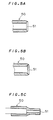
- a large-diameter portion 51 at a front end of a ferrule 50 and having an inner diameter greater than that of the ferrule 50 is required as a space for filling therein the plastic fiber melted and softened by means of the hot plate as shown in Figs. 5A to 5C.
- the large-diameter portion 51 is basically of a rectangular cross-sectional configuration as shown in Fig. 5A.
- the large-diameter portion 51 has, in cross section, a rounded corner as shown in Fig. 5B and a chamfered corner as shown in Fig. 5C.
- a high-heat-resistant plastic fiber which is less susceptible to changes than general plastic fibers in hardness of the fiber at high temperatures is subjected to stress concentration on a portion of the fiber which is filled in the large-diameter portion of the ferrule due to fiber shrinkage.
- the thermal shock test has caused cracks in the stress concentrated portion.
- a ferrule comprises: a tubular core wire holding portion for receiving and holding a core wire portion of a plastic fiber; and a tubular sheath holding portion for receiving and holding a sheath portion of the plastic fiber, the core wire holding portion including a large-diameter portion at a front end thereof having a tapered inner surface such that an inner diameter thereof increases toward the front end, wherein an angle at which the tapered inner surface is flared is not more than 30 degrees.
- the tapered inner surface of the large-diameter portion receiving the front end of the fiber softened by the hot plate treatment is flared at the angle of not more than 30 degrees.
- the angle at which the tapered inner surface is flared is not less than 15 degrees.
- the angle of flare is preferably in the range from 15 to 30 degrees since it does not necessitate the increase in depth of the large-diameter portion.
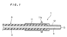
- a ferrule 1 comprises a sheath holding portion 11 for holding a sheath portion a of a plastic fiber A and a core wire holding portion 12 for holding a core wire portion b of the plastic fiber A.
- the ferrule 1 is mounted in a connector housing and the like when in use.
- the sheath holding portion 11 and the core wire holding portion 12 have inner diameters slightly greater than the outer diameters of the sheath portion a and core wire portion b of the plastic fiber A, respectively.
- the sheath holding portion 11 is provided with a flange portion 11a which contacts a coiled spring when the ferrule 1 is mounted in the connector housing.
- a large-diameter portion 13 is provided at a front end of the core wire holding portion 12 and receives a front end portion of the core wire portion b of the plastic fiber A softened by hot plate treatment.
- the large-diameter portion 13 has a tapered inner surface such that an inner diameter thereof increases toward the front end.
- the angle of flare of the large-diameter portion 13 is 15 degrees.
- the angle of flare of the tapered inner surface of the large-diameter portion 13 is, the more effectively an end surface of the fiber is prevented from sinking inwardly from an end of the ferrule due to shrinkage of the fiber.
- the angle of flare is preferably not more than 30 degrees.
- the angle of flare is ideally preferably in the range from 15 to 30 degrees.
- the plastic fiber A with the ferrule 1 is subjected to the hot plate treatment and checked for the strength of the fiber at front end and for cracks due to the thermal shock test when the angle of flare of the tapered inner surface of the large-diameter portion 13 is 15 degrees, 30 degrees, 45 degrees, and 60 degrees.
- the results are shown in Table 1 and Fig. 4.
- the dimensions of the ferrule used in this experiment are as follows: the diameter D of the ferrule is 2 mm; the maximum aperture diameter d of the large-diameter portion 13 is 1.4 mm; and the diameter of the fiber ⁇ is 1 mm.
- Table 1 angle 100 cycles 250 cycles 500 cycles 750 cycles 1000 cycles 15° ⁇ ⁇ ⁇ ⁇ ⁇ 30° ⁇ ⁇ ⁇ X 45° ⁇ X 60° ⁇ X where the open circle represents the absence of cracks, and the cross represents the generation of cracks.
Landscapes
- Physics & Mathematics (AREA)
- General Physics & Mathematics (AREA)
- Optics & Photonics (AREA)
- Mechanical Coupling Of Light Guides (AREA)
Applications Claiming Priority (3)
| Application Number | Priority Date | Filing Date | Title |
|---|---|---|---|
| JP2328394 | 1994-01-24 | ||
| JP23283/94 | 1994-01-24 | ||
| JP02328394A JP3248331B2 (ja) | 1994-01-24 | 1994-01-24 | フェルール端末 |
Publications (3)
| Publication Number | Publication Date |
|---|---|
| EP0664466A2 true EP0664466A2 (de) | 1995-07-26 |
| EP0664466A3 EP0664466A3 (de) | 1996-03-27 |
| EP0664466B1 EP0664466B1 (de) | 2002-05-29 |
Family
ID=12106284
Family Applications (1)
| Application Number | Title | Priority Date | Filing Date |
|---|---|---|---|
| EP94120014A Expired - Lifetime EP0664466B1 (de) | 1994-01-24 | 1994-12-16 | Steckerstift |
Country Status (4)
| Country | Link |
|---|---|
| US (1) | US5590231A (de) |
| EP (1) | EP0664466B1 (de) |
| JP (1) | JP3248331B2 (de) |
| DE (1) | DE69430692T2 (de) |
Cited By (4)
| Publication number | Priority date | Publication date | Assignee | Title |
|---|---|---|---|---|
| EP0777140A1 (de) * | 1995-12-01 | 1997-06-04 | Sumitomo Electric Industries, Ltd. | Optische Steckeranordnung, Glasfaserleitungs-Konstruktion und Herstellungsverfahren für eine Glasfaserleitungs-Konstruktion |
| US5661832A (en) * | 1995-11-28 | 1997-08-26 | Sumitomo Electric Industries, Ltd. | Optical connector structure, optical fiber cord assembly and process of producing optical fiber cord assembly |
| EP0862073A1 (de) * | 1997-02-26 | 1998-09-02 | Sumitomo Wiring Systems, Ltd. | Hülse mit einer sich verjüngenden optischen Faser |
| EP0903602A3 (de) * | 1997-09-11 | 1999-11-24 | Sumitomo Wiring Systems, Ltd. | Anordnung zum Verbinden einer Lichtleitfaser aus Kunstoff an einen Photodetektor |
Families Citing this family (3)
| Publication number | Priority date | Publication date | Assignee | Title |
|---|---|---|---|---|
| JP3581580B2 (ja) * | 1998-08-14 | 2004-10-27 | キヤノン株式会社 | 現像装置 |
| JP2002156550A (ja) * | 2000-09-06 | 2002-05-31 | Sony Corp | 接続装置、光信号ケーブルおよび光通信ケーブルの製造方法 |
| JP5777490B2 (ja) * | 2011-10-31 | 2015-09-09 | 京セラ株式会社 | 光伝送構造体 |
Family Cites Families (13)
| Publication number | Priority date | Publication date | Assignee | Title |
|---|---|---|---|---|
| US1911406A (en) * | 1933-05-30 | Jtehrulei foe implement handles | ||
| US3372476A (en) * | 1967-04-05 | 1968-03-12 | Amp Inc | Method of making permanent connections between interfitting parts |
| GB1479575A (en) * | 1976-05-25 | 1977-07-13 | Standard Telephones Cables Ltd | Terminating optical fibres |
| US4191447A (en) * | 1978-04-27 | 1980-03-04 | International Telephone And Telegraph Corporation | Fiber optic termination and method of making same |
| US4510005A (en) * | 1982-09-28 | 1985-04-09 | Allied Corporation | Method and apparatus for reshaping and polishing an end face of an optical fiber |
| KR910006773B1 (ko) * | 1984-01-30 | 1991-09-02 | 후루까와덴끼 고오교오 가부시끼가이샤 | 페루울 부(付) 플라스틱 광파이버 코오드 |
| JPS60186812A (ja) * | 1984-03-06 | 1985-09-24 | Toyota Motor Corp | 光コネクタ |
| JPS63104005A (ja) * | 1986-10-21 | 1988-05-09 | Sumitomo Electric Ind Ltd | 光フアイバ用フエル−ル |
| JPS63127865A (ja) * | 1986-11-19 | 1988-05-31 | Sumitomo Electric Ind Ltd | 光コネクタフエル−ルの加工方法 |
| JPS63316005A (ja) * | 1987-06-19 | 1988-12-23 | Yamatake Honeywell Co Ltd | 光フアイバ−用光案内装置 |
| JPH06100696B2 (ja) * | 1988-12-23 | 1994-12-12 | 日本電気株式会社 | 光コネクタフェルール |
| JPH03114805U (de) * | 1990-03-09 | 1991-11-26 | ||
| US5113476A (en) * | 1990-11-08 | 1992-05-12 | Mitsubishi Rayon Company Ltd. | Light attenuator and process for fabrication thereof |
-
1994
- 1994-01-24 JP JP02328394A patent/JP3248331B2/ja not_active Expired - Fee Related
- 1994-11-29 US US08/346,021 patent/US5590231A/en not_active Expired - Lifetime
- 1994-12-16 DE DE69430692T patent/DE69430692T2/de not_active Expired - Lifetime
- 1994-12-16 EP EP94120014A patent/EP0664466B1/de not_active Expired - Lifetime
Cited By (4)
| Publication number | Priority date | Publication date | Assignee | Title |
|---|---|---|---|---|
| US5661832A (en) * | 1995-11-28 | 1997-08-26 | Sumitomo Electric Industries, Ltd. | Optical connector structure, optical fiber cord assembly and process of producing optical fiber cord assembly |
| EP0777140A1 (de) * | 1995-12-01 | 1997-06-04 | Sumitomo Electric Industries, Ltd. | Optische Steckeranordnung, Glasfaserleitungs-Konstruktion und Herstellungsverfahren für eine Glasfaserleitungs-Konstruktion |
| EP0862073A1 (de) * | 1997-02-26 | 1998-09-02 | Sumitomo Wiring Systems, Ltd. | Hülse mit einer sich verjüngenden optischen Faser |
| EP0903602A3 (de) * | 1997-09-11 | 1999-11-24 | Sumitomo Wiring Systems, Ltd. | Anordnung zum Verbinden einer Lichtleitfaser aus Kunstoff an einen Photodetektor |
Also Published As
| Publication number | Publication date |
|---|---|
| DE69430692T2 (de) | 2002-10-24 |
| US5590231A (en) | 1996-12-31 |
| DE69430692D1 (de) | 2002-07-04 |
| EP0664466B1 (de) | 2002-05-29 |
| EP0664466A3 (de) | 1996-03-27 |
| JPH07209552A (ja) | 1995-08-11 |
| JP3248331B2 (ja) | 2002-01-21 |
Similar Documents
| Publication | Publication Date | Title |
|---|---|---|
| US3861781A (en) | Separable optical fiber connector and the method of manufacturing the same | |
| US4648688A (en) | Connector for fiber optic member including polishing fixture and method of terminating same | |
| CA1054413A (en) | Termination of optical fibre cables | |
| US6282349B1 (en) | Launch fiber termination | |
| US4773725A (en) | Termination of a fiber optic transmission member and method therefore | |
| JP3347399B2 (ja) | 光コネクタ | |
| US4116655A (en) | Method for making optical-fibre cables | |
| US4623220A (en) | Laser to fiber connection | |
| EP0415625A3 (en) | Connector assemblies for optical fiber light cables | |
| JPS61163306A (ja) | フアイバ整合−維持装置 | |
| GB2097149A (en) | Apparatus for aligning an optical fiber with a collimating lens | |
| EP0664466A2 (de) | Steckerstift | |
| US5502784A (en) | Heat insulating connector for plastic optical fibers | |
| CN1388393A (zh) | 用于光信号的变换插头及该变换插头的制造方法 | |
| WO1995022776A1 (en) | Fiber optic connector with epoxy preform | |
| US5699466A (en) | Optical fiber connector | |
| US3226589A (en) | Fiber type light transferring devices and method of making the same | |
| US4869571A (en) | Plug pin for a light waveguide | |
| JP2005352495A (ja) | 光ファイバ束端の製造装置及び方法、同装置及び方法を用いて製造される改良光ファイバ束 | |
| EP0095281A2 (de) | Verbindungsglied für ein faseroptisches Bauteil | |
| EP0449489B1 (de) | Zusammengesetzte Isolatoren mit eingebauter optischer Faser und Verfahren zu deren Herstellung | |
| JPS58171011A (ja) | 熱収縮チユ−ブ加熱治具 | |
| JPH04274202A (ja) | 光ファイバーの終端 | |
| EP0592822B1 (de) | Befestigungsmethode einer optischen Faser an einen Koppler | |
| JP3441184B2 (ja) | 光ファイバ整列体の製造方法 |
Legal Events
| Date | Code | Title | Description |
|---|---|---|---|
| PUAI | Public reference made under article 153(3) epc to a published international application that has entered the european phase |
Free format text: ORIGINAL CODE: 0009012 |
|
| AK | Designated contracting states |
Kind code of ref document: A2 Designated state(s): DE FR GB |
|
| PUAL | Search report despatched |
Free format text: ORIGINAL CODE: 0009013 |
|
| AK | Designated contracting states |
Kind code of ref document: A3 Designated state(s): DE FR GB |
|
| 17P | Request for examination filed |
Effective date: 19960329 |
|
| 17Q | First examination report despatched |
Effective date: 19960722 |
|
| APAB | Appeal dossier modified |
Free format text: ORIGINAL CODE: EPIDOS NOAPE |
|
| APAB | Appeal dossier modified |
Free format text: ORIGINAL CODE: EPIDOS NOAPE |
|
| APAD | Appeal reference recorded |
Free format text: ORIGINAL CODE: EPIDOS REFNE |
|
| APCB | Communication from the board of appeal sent |
Free format text: ORIGINAL CODE: EPIDOS OBAPE |
|
| APCB | Communication from the board of appeal sent |
Free format text: ORIGINAL CODE: EPIDOS OBAPE |
|
| APCB | Communication from the board of appeal sent |
Free format text: ORIGINAL CODE: EPIDOS OBAPE |
|
| APCB | Communication from the board of appeal sent |
Free format text: ORIGINAL CODE: EPIDOS OBAPE |
|
| APAB | Appeal dossier modified |
Free format text: ORIGINAL CODE: EPIDOS NOAPE |
|
| GRAG | Despatch of communication of intention to grant |
Free format text: ORIGINAL CODE: EPIDOS AGRA |
|
| GRAH | Despatch of communication of intention to grant a patent |
Free format text: ORIGINAL CODE: EPIDOS IGRA |
|
| GRAA | (expected) grant |
Free format text: ORIGINAL CODE: 0009210 |
|
| AK | Designated contracting states |
Kind code of ref document: B1 Designated state(s): DE FR GB |
|
| REG | Reference to a national code |
Ref country code: GB Ref legal event code: FG4D |
|
| REF | Corresponds to: |
Ref document number: 69430692 Country of ref document: DE Date of ref document: 20020704 |
|
| ET | Fr: translation filed | ||
| PLBE | No opposition filed within time limit |
Free format text: ORIGINAL CODE: 0009261 |
|
| STAA | Information on the status of an ep patent application or granted ep patent |
Free format text: STATUS: NO OPPOSITION FILED WITHIN TIME LIMIT |
|
| 26N | No opposition filed |
Effective date: 20030303 |
|
| APAH | Appeal reference modified |
Free format text: ORIGINAL CODE: EPIDOSCREFNO |
|
| PGFP | Annual fee paid to national office [announced via postgrant information from national office to epo] |
Ref country code: GB Payment date: 20101215 Year of fee payment: 17 |
|
| PGFP | Annual fee paid to national office [announced via postgrant information from national office to epo] |
Ref country code: DE Payment date: 20101208 Year of fee payment: 17 |
|
| PGFP | Annual fee paid to national office [announced via postgrant information from national office to epo] |
Ref country code: FR Payment date: 20111219 Year of fee payment: 18 |
|
| GBPC | Gb: european patent ceased through non-payment of renewal fee |
Effective date: 20121216 |
|
| REG | Reference to a national code |
Ref country code: FR Ref legal event code: ST Effective date: 20130830 |
|
| REG | Reference to a national code |
Ref country code: DE Ref legal event code: R119 Ref document number: 69430692 Country of ref document: DE Effective date: 20130702 |
|
| PG25 | Lapsed in a contracting state [announced via postgrant information from national office to epo] |
Ref country code: DE Free format text: LAPSE BECAUSE OF NON-PAYMENT OF DUE FEES Effective date: 20130702 |
|
| PG25 | Lapsed in a contracting state [announced via postgrant information from national office to epo] |
Ref country code: FR Free format text: LAPSE BECAUSE OF NON-PAYMENT OF DUE FEES Effective date: 20130102 Ref country code: GB Free format text: LAPSE BECAUSE OF NON-PAYMENT OF DUE FEES Effective date: 20121216 |