EP0664725B1 - Anlage zur abscheidung von leichten kohlenwasserstoffen und aromaten von emulsionen - Google Patents
Anlage zur abscheidung von leichten kohlenwasserstoffen und aromaten von emulsionen Download PDFInfo
- Publication number
- EP0664725B1 EP0664725B1 EP94915523A EP94915523A EP0664725B1 EP 0664725 B1 EP0664725 B1 EP 0664725B1 EP 94915523 A EP94915523 A EP 94915523A EP 94915523 A EP94915523 A EP 94915523A EP 0664725 B1 EP0664725 B1 EP 0664725B1
- Authority
- EP
- European Patent Office
- Prior art keywords
- rectification
- water
- unit
- condensate
- devices
- Prior art date
- Legal status (The legal status is an assumption and is not a legal conclusion. Google has not performed a legal analysis and makes no representation as to the accuracy of the status listed.)
- Expired - Lifetime
Links
Images




Classifications
-
- B—PERFORMING OPERATIONS; TRANSPORTING
- B01—PHYSICAL OR CHEMICAL PROCESSES OR APPARATUS IN GENERAL
- B01D—SEPARATION
- B01D17/00—Separation of liquids, not provided for elsewhere, e.g. by thermal diffusion
-
- E—FIXED CONSTRUCTIONS
- E21—EARTH OR ROCK DRILLING; MINING
- E21B—EARTH OR ROCK DRILLING; OBTAINING OIL, GAS, WATER, SOLUBLE OR MELTABLE MATERIALS OR A SLURRY OF MINERALS FROM WELLS
- E21B43/00—Methods or apparatus for obtaining oil, gas, water, soluble or meltable materials or a slurry of minerals from wells
- E21B43/34—Arrangements for separating materials produced by the well
- E21B43/35—Arrangements for separating materials produced by the well specially adapted for separating solids
Definitions
- the present invention relates generally to the separation of hydrocarbons from water and more particularly to an apparatus and a method for the separation of light-weight hydrocarbons and aromatics from production water.
- Centrifuges are utilized for the separation of emulgated production water on offshore production platforms operated by the oil and gas industries.
- the best values attained for overboard water are 80 ppm.
- the value reached by devices like that does not fulfill the legally defined limits are 80 ppm.
- Another method to get rid of such emulsions is to inject them back into the sea bottom which is neither regarded as being optimum.
- the problem to be solved is the development of an apparatus for the separation of light-weight hydrocarbons and aromatics from production water, so that the content of said hydrocarbons and aromatics is minimized.
- an apparatus EP-A-0128071 comprising a rectification unit consisting a lower and an upper part.
- an apparatus for the separation of light-weight hydrocarbons and aromatics from production water in an emulgated water feed stream comprising a vacuum rectification unit consisting of a lower and an upper part, wherein :
- the upper half of the rectification-unit comprises further a filter pack above the condenser for holding back condensate and solids.
- the upper half of the rectification-unit can comprise baffle plates to lead the remains of the vapor towards an outlet on top-center of the rectification-unit.
- the upper half of the rectification-unit further comprises devices for evacuating the remains of the vapor whereby said devices may additionally or solely comprise one or more means selected from the group consisting of evacuation pipe, condensate trap, retention-valve, and dry-running vacuum pump.
- the apparatus can be designed the way that the perforated stage vessel contains a pipe leading to the center of the inside section of the rectification-unit and at an angle of 90° down to the perforated plate-trays to the center outlet of the perforated stage vessel.
- the flow of the emulgated water is directed between the housing of the perforated stage vessel and the outer mantel of the rectification-unit from the center outlet of the perforated stage vessel upwardly to the spraying devices.
- the apparatus can comprise devices for leading the remaining liquid fraction with a boiling point above the one of water, to the sump of the rectification-unit flowing down through the tunnel plate sections and the perforated plate sections to the sump of the rectification - unit.
- the apparatus can comprise devices to blow down periodically the sump, with the sump being delivered to a storage tank or submitted to further processing.
- the apparatus further comprises devices to blow down automatically the sump with the sump being delivered to a storage tank or submitted to a further processing.
- the perforated stage vessel further comprises devices allowing counterflow system rectification within the perforated stage vessel.
- the apparatus according to the present invention can additionally comprise means for the injection of freshwater to prevent saturation of the sump.
- Inductive conductivity sensor may be used to generate signals being used for the prevention of saturation of the sump in a further embodiment.
- the upper part of the rectification-unit further comprises devices for removing the condensate.
- the devices for removing the condensate in/from the upper part of the rectification-unit comprises at least one condensate pump.
- a condensate pump being activated by at least one floatswitch located in the condensate-collecting-basin.
- At least one suction fine for a condensate pump is fitted to the condensate-collecting-basin below the long-position of the condensate.
- the condensate is removed from the condensate-collecting-basin passing a heat exchanger mounted inside the rectification--unit before being submitted to further processing or storage.
- the inventive apparatus may further comprise devices for preventing flooding of the rectification-unit.
- devices for preventing flooding comprising a pipe, a solenoid-valve and pumping means, by pumping excess fluid back to an appropriate earlier processing step and the corresponding devices, respectively.
- devices for avoiding dry-running of the rectification unit are comprised.
- said devices for avoiding dry-running of the rectification-unit comprise a pipe, a solenoid-valve and a freshwater supply controlled by one or more float switches.
- a condensate obtained from rectification is subjected to UV-oxidation.
- the apparatus according to the present invention with a measuring devices for aliphatics which is connected with the fine releasing the processed production water to the environment, for analysis of oil-in-water contents before the processed production water is released.
- a measuring devices for aliphatics connected with the line releasing a processed production water to the environment, for analysis of oil-in-water contents, before the processed production water is released, is coupled to a solenoid-valve which will close the line releasing the processed production water and recycle the contaminated water back to an earlier processing step and the corresponding devices, respectively, if preset values for aliphatics in processed production water are not met.
- the apparatus comprises a measuring devices for aromatics which is connected with the line releasing the processed production water to the environment for analysis of oil-in-water contents before the processed production water is released.
- a measuring device for aromatics is connected with a line releasing a processed production water to the environment, for analysis of oil-in-water contents, before the processed production water is released, is coupled to a solenoid-valve which will close the line releasing the processed production water and recycle contaminated water back to an earlier processing step and the corresponding devices, respectively, if preset values for aromatics in processed production water are not met.
- the apparatus is comprised of three insulated sections.
- the apparatus is mounted on a skid.
- the rectification-unit is a vacuum rectification-unit.
- the invention further relates to a method for the separation of light-weight hydrocarbons and aromatics from production water being characterized by the flow of emulgated water through an apparatus with the emulgated water to be treated within the rectification-unit being heated to a temperature of about 40°C at a pressure of 7400 Pa (55,5 Torr).
- the advantages related to the apparatus according to the present invention refer particularly to the content of aliphatics and aromatics. Said apparatus allows the reduction of the concentration of aliphatics and aromatics far beyond the limit accessible right now via centrifuges for the separation of emulgated production water on offshore production platforms.
- the devices for spraying the emulgated water over the top section of the perforated plates comprising a nozzle ring at the upper end of the perforated stage vessel are especially beneficial because spraying causes faster vaporization and increases the flow rate of the emulgated water to be processed.
- the inventive apparatus comprising devices allowing counterflow system rectification within the perforated stage vessel offers further advantages.
- the steam phase contains all components that are supposed to be separated, where in general the lighter volatile components will appear in a higher concentration in the steam than in the liquid. In this case the component will be concentrated by a single vaporization, but not separated. The latter one being possible with the counterflow-system rectification.
- a further advantage of an embodiment of the present apparatus is obtained by the condensate being removed from the condensate-connecting-basin, passing the heat exchanger mounted inside the rectification-unit before being submitted to further processing or storage. Because of this electric energy can be saved, rendering the operation of the inventive apparatus more economic.
- Safety of operations is realized by the measures taken to avoid dry-running such as incorporating devices for avoiding dry-running of the rectification-unit comprising a pipe, a solenoid-valve and a freshwater supply control by one or more floatswitches.
- a further advantage of the inventive apparatus is based on the reduction of the concentration of aromatics by linking an UV-oxidation unit to the rectification-unit.
- the apparatus comprises measuring devices for aliphatics and/or aromatics which are connected with the line releasing the process production water to the environment, for analysis of oil-in-water contents, before the processed production water is released, and which are coupled to solenoid-valves which will close the line releasing the process production water and recycle the contaminated water back to an earlier process step and a corresponding devices, respectively, if preset values for aromatics and/or aliphatics in processed production water are not met. Because of this online control less samples have to be taken to laboratories for analysis by helicopters.
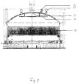
- Fig. 1 is showing the rectification-unit of the inventive apparatus for the separation of light-weight hydrocarbons and aromatics from production water.
- the rectification-unit can be divided into several functional units shown in more details in figures 2 to 5, such as head (I*), center-top (II*), lower section (III*), and sump (IV*).
- Pipe 10 is welded airtight to the housing of (E), leading then to the center 11 of the inside section and at an angle of 90° down through the perforated plate trays 12, to the center outlet 14 of the vessel 13.
- the pipe is welded to the bottom of this vessel.
- the perforated stage vessel fills out the lower half of the rectification-unit and serves as a waterlock to hold the vacuum in the unit stable.
- the emulgated water flows now between the housing of the vessel 13a and the outer mantel of the rectification-unit 16 upward to the top.
- the nozzle ring 17 has been welded in, where the emulgated feedwater is pressed through the nozzles and sprayed out over the top section of the perforated plates 12. Spraying in the emulgated water causes faster vaporization and increases the flow rate.
- the emulgated water will be heated up to the boiling point (at approximately 40°C an a vacuum of 7400 Pa).
- the steam phase contains all components that are supposed to be separated, where in general the lighter volatile components will appear in a higher concentration in the steam than in the fluid. In this case the components will be concentrated by a single vaporization, but not separated. This is possible with the counterflow-system rectification.
- the exchange of the media can be improved by increasing the flow-speed, which causes the laminar sub-surface to be thinner, but the turbulence increases.
- a concentrate pump (Ppe-1) delivers the concentrated fluid to the dirty oil/concentrated tank (K-1).
- a density control 23 activates a solenoid-valve (MV-2) and a concentrate pump (Ppe-1).
- the inductive conductivity sensor prevents saturation (chlorides) of the sump by injection of freshwater.
- the vapor In the upper half of the rectification-unit the vapor is forced to a hydrocyclone X and after this through a condenser 24 where a condensate-collecting-basin 25 is located, where the vapor is forced through and condenses.
- the condenser will be supplied with freshwater through the pipes 26 and 27.
- the condensate will be collected in the condensate-collecting-basin 25 and through pipe 28 and a retention-value RV-5 pumped out by the condensate pump.
- the condensate pump will be activated by means of floatswitches located in the condensate-collecting-basin.
- a discharge pipe 28 is adapted acting as suction line of a condensate pump (Ppe-2).
- the suction line is fitted to the condensate-collecting-basin below the low position of the condensate (floatswitch) to secure the vacuum.
- the condensate pump (Ppe-2) the condensate will flow through a pipe (28a) and heat exchanger 41 in the lower section of the rectification-unit into a skid mounted condensate tank (G).
- the condensate will transfer its heat to the heat exchanger to the entering emulgated water, saving in this way electric energy.
- a filter pack 30 has been installed, holding condensate and solids back. The remains of the vapor will be led around baffle plates 31 towards the outlet 32 on top center of the rectification-unit and evacuated through a pipe (33).
- a contact-manovacuummeter 35 has been installed in the head of the rectification-unit, connected with the electrical heater elements 18. Should the vacuum be lost, the heater elements will automatically be switched off to avoid increasing steam pressure. Furtheron a pressure-relief-valve 36 is installed.
- Fig. 2 is showing the lower section of the rectification-unit as illustrated in fig. 1.
- Pipe 10 is leading to the center 11 of the inside section of the perforated stage vessel forming the lower part of the rectification-unit.
- At the bottom of the vessel outlet 14 allows the emulgated water to exit from the vessel to be flown between the housing of the vessel 13 and the outer mantel of the rectification-unit 16 upward to the top.
- Heater elements 18 are used to heat up the emulgated water to the boiling point at approximately 40°C and a vacuum of 7400 Pa (55,5 Torr).
- a density control 23 activates a solenoid-valve which is used to blow down automatically and periodically the sump of the unit. Additionally a concentrate pump is activated by them.
- inductive conductivity sensor 23a is mounted in the sump region of the perforated stage vessel within the rectification column to prevent saturation of the sump by injection of freshwater.
- heat exchanger 41 can be seen being supplied with energy by the condensate collected within the condensate-collecting-basin 25 in the upper half of the rectification - unit.
- Fig. 3 is showing the lower section of the rectification-unit as illustrated in fig. 1. Again line 10 can be seen leading in the center 11 down to the perforated plate trays 12. Heat exchanger is supplied with a condensate via lines 28a to save energy. Emulsion is directed from the sump area of the perforated stage vessel to the upper end of the vessel where the nozzle ring 17 is welded in. There the emulgated feedwater is pressed through the nozzles and sprayed out over top section of the perforated plates 12.
- Fig. 4 is showing the center-top of the rectification-unit as illustrated in fig. 1.
- the most characteristic device in this section is hydrocyclone X within the tunnel plate section 19 and condensate-collecting-basin 25. Additional floatswitches SS-1 which are located in the condensate-collecting-basin can be seen.
- Discharge pipe 28 originates at outlet opening 29, acting as suction line of a condensate pump (Ppe-2).
- Fig. 5 is showing the head of the rectification-unit as illustrated in fig. 1.
- Filter pack 30 is installed to hold back condensate and solids.
- Baffle plates 31 lead the remains of the vapor towards to outlet 32.
- Contact-manovacuummeter 35 has also been installed and connected with electrical heater elements 18 located in the sump of the rectification-unit. Furtheron a pressure relief-valve 36 is installed.
- Fig. 6 shows a block-diagram of the apparatus for the separation of light-weight hydrocarbons and aromatics from production water.
- Production water flows from the coalesting tank A through pipe 1, the strainer 2 and the retention-valve RV-6 into the inventive apparatus and through pipe 3 to the DVZ-honeycomb separator B.
- the DVZ separates the oilphase from the emulgated water and returns the dirty oil through the pipes 4, 6 and 7 to the dirty oil tank K-1.
- the emulgated water leaves the separator through pipe 51 with an approximate pressure of 1.5 bar and flows via the 3-way solenoid-valve 3MV-1 and pipe 8 into the skid-mounted emulsion tank D.
- water and air are necessary (air 5 to 7 bar). Fresh water flows into the separator through valve V-1, pipe 5, strainer 9 and retention-valve RV-1.
- the air supply with 5 - 7 bar is led through a bail valve KV1, pipe 10, air pressure reducing station 11a and pneumatic control valve PV-1 into the DVZ-separator.
- the DVZ-separator is governed by a DECKMA OCD-2 oil-in-water monitor C.
- a measuring line is branching off from the pipe 8, leading into the OCD-2 monitor. After the measuring procedure the fluid leaves the OCD-2 monitor through pipe 49 back into the coalesting tank A.
- the monitor will activate the 3-way-solenoid control valve 3MV-1 in such a way that the contaminated water will flow through pipe 7 back into the dirty oil tank K-1.
- the emulgated water will flow through valve 3MV-1 and pipe 8 into emulsion tank D.
- pump Ppe-5 and pipe 9 the emulsion flows to the heat exchanger L, via pipe 10 and RV-4 into vacuum rectification-unit E on the side of the rectification-unit inlet at medium hight.
- the concentrate pump Ppe-1 delivers the concentrate fluid to the dirty oil/concentrate tank K-1.
- a densitiy control 23 activates solenoid valve MV-2 and concentrate pump Ppe-1.
- the condensate obtained and collected in the condensate-collecting-basin 25 of the upper half of the rectification-unit will be pumped out by condensate pump Ppe-2 through pipe 28 and retention valve RV-5.
- the condensate pump will be activated by means of floatswitches SS-1 located in the condensate-collecting-basin.
- Solenoid-valve MV-3 will be activated by means of floatswitches (not shown), mounted inside the rectification unit.
- heat exchangers 41 have been installed on the inside of the unit so that, if available, also cooling water of generator-sets or turbines can be led through.
- the UV-oxidation plant H After the skid-mounted condensate-bottom tank G, the UV-oxidation plant H has been installed.
- the condensator will be pumped out of the tank by means of a magnetic-coupled pump Ppe-4, controlled by floatswitches (not shown) mounted inside the bottom tank G and delivered through the UV-oxidation plant. Here the remaining aromatics will be eliminated.
- the aliphatic measuring device comprises an OMS-40 monitor.
- the OMS-40 monitor J has been connected with the overboard discharge line 45 by means of a measuring line 47.
- This unit is especially designed for analysing oil-in-water contents without solid according to the dutch regulation NEN 6675 mod.
- the monitor is equipped with a printer.
- the output-signals (in ppm) will be transmitted to the receiving equipment on the center-line-platform.
- the OMS-40 is connected with a 3-way solenoid-valve 3 MV-2. Should the ppm-values exceed their limit of 40 ppm, the solenoid-valve will close the overboard discharge 45 and recycle the contaminated water back through the pipe 21 by means of a transfer-pump Ppe-1 to the coalesting tank A on board the platform.
- the aromatic measuring device I has been connected with the overboard-discharge line 45 by means of a measuring line 46.
- This unit is especially designed for analysing aromatic contents in water.
- the unit is equipped with a printer.
- the output signals (in ppm) will be transmitted to the receiving equipment on the center-line-platform.
- the device is connected with a 3-way solenoid-valve 3MV-2. Should the ppm-values exceed the limit of 40 ppm the solenoid valve will close the overboard discharge 45 and recycle the contaminated water back to pipe 21 by means of transfer pump Ppe-1 to the coalesting tank A onboard the platform.
- the transmitted signals from the different units within the inventive apparatus will be received on the center line equipment and shown a monitor as described before.
- Fig. 7 is showing a flow-diagram of the inventive apparatus for the separation of light-weight hydrocarbons and aromatics from production water.
- the flow and processing of production water is identical to the one illustrated in Fig. 6.
- Fig. 8 is showing an arrangement of components and skid-mounting-plates.
- Fig. 9 is showing a skid with three containers for the reception of the inventive apparatus.
Landscapes
- Geology (AREA)
- Life Sciences & Earth Sciences (AREA)
- Engineering & Computer Science (AREA)
- Mining & Mineral Resources (AREA)
- Physics & Mathematics (AREA)
- Environmental & Geological Engineering (AREA)
- Fluid Mechanics (AREA)
- General Life Sciences & Earth Sciences (AREA)
- Geochemistry & Mineralogy (AREA)
- Thermal Sciences (AREA)
- Chemical & Material Sciences (AREA)
- Chemical Kinetics & Catalysis (AREA)
- Extraction Or Liquid Replacement (AREA)
- Heat Treatment Of Water, Waste Water Or Sewage (AREA)
- Vaporization, Distillation, Condensation, Sublimation, And Cold Traps (AREA)
Claims (27)
- Anlage zur Abscheidung leichter Kohlenwasserstoffe und Aromate aus Prozesswasser in einem Strom zur Zuleitung von emulgiertem Wasser, welche eine aus einem oberen und einem unteren Teil bestehende Einheit (E) zur Vakuumrektifikation aufweist, bei welcher:im unteren Teil der Rektifiziereinheit (E) ein durchbrochener Stufentank (13) enthalten ist und Vorrichtungen zur Aufnahme (10) und Erwärmung (18) von emulgiertem Wasser aufweist, wobei der untere Teil der Einheit (E) des weiteren Einrichtungen (14) zum Durchleiten des erwärmten emulgiertem Wassers durch den Ringraum zwischen dem durchbrochenen Stufentank (13) und einem äußeren Mantel (16) auf der Druckseite der Einheit (E) zu einem Düsenring (17) oben an dem durchbrochenen Stufentank (13) zum Versprühen von emulgiertem Wasser über den oberen Abschnitt der Lochplatten (12) aufweist, die innerhalb des inneren Mantels auf einer oder mehreren Ebenen zur Rektifizierung im Gegenstrom und zum Konzentrieren von in dem Prozesswasser enthaltenen organischer Verbindungen in einen Dampfstrom angeordnet sind,und der obere Teil der Einheit (E) zur Vakuumrektifikation einen Hydrozyklon (X), welcher den Dampfstrom aufnimmt, sowie einen abströmseitigen Kondensierer (24) aufweist, welcher einen Behälter (25) zum Auffangen von Kondensat und zum Kondensieren des am durchbrochenen Stufentank (13) erzeugten Dampfes, wobei das Kondensat einer weiteren Behandlung unterzogen oder einem Lagertank zugeleitet wird.
- Anlage nach Anspruch 1,
bei welcher die obere Hälfte der Rektifiziereinheit (E) des weiteren über dem Kondensierer (24) eine Filterbaugruppe (30) zum Zurückhalten von Kondensat und Feststoffen aufweist. - Anlage nach Anspruch 1 oder 2,
bei welcher die obere Hälfte der Rektifiziereinheit (E) des weiteren Leitplatten (31) aufweist, welche die Dampfreste zu einem Auslass (32) oben in der Mitte der Rektifiziereinheit leiten. - Anlage nach einem der Ansprüche 1 bis 3,
bei welcher die obere Hälfte der Rektifiziereinheit (E) des weiteren Vorrichtungen zum Austragen der Dampfteste aufweist, wobei die Vorrichtungen gegebenenfalls zusätzlich oder ausschließlich eine oder mehrere Einrichtungen aufweisen, die aus der Gruppe gewählt sind, welche eine Austragsleitung (33), einen Kondensatabscheider (34), ein Rückhalteventil (VRV-1) und eine Trockenlauf-Vakuumpumpe (F) umfasst. - Anlage nach einem der Ansprüche 1 bis 4, bei welcher der durchbrochene Stufentank (13) folgendermaßen aufgebaut ist:das Einlassrohr (10) für emulgiertes Wasser führt durch den äußeren Mantel des Rektifiziergehäuses und das Gehäuse des durchbrochenen Stufentanks zur Mitte des durchbrochenen Stufentanks (innerer Abschnitt 11) der Rektifiziereinheit (E) und unter einem Winkel von 90° nach unten durch die durchbrochenen Plattenböden (12) zum Mittelauslass (14) des durchbrochenen Stufentanks (13), wo das emulgierte Wasser aus dem durchbrochenen Stufentank mit einem Druck von etwa 1,5 bar austritt und in die Steigkammer zwischen dem inneren und äußeren Mantel eintritt.
- Anlage nach einem der Ansprüche 1 bis 5, bei welcher der Strom emulgierten Wassers nach oben zwischen dem Gehäuse des durchbrochenen Stufentanks (13) und dem äußeren Mantel/Gehäuse (16) der Rektifiziereinheit (E) unter einem Druck von etwa 1,5 bar aus dem Mittelauslass (14) des durchbrochenen Stufentanks (13) aufwärts zu den Sprühvorrichtungen (Düsen 17) geleitet wird und dabei unter Vorerwärmung des emulgierten Wassers an den unteren Plattenwärmetauschern vorbeiströmt.
- Anlage nach einem der Ansprüche 1 bis 6, welche des weiteren Vorrichtungen aufweist, welche die verbleibende Flüssigkeitsfraktion mit einem Siedepunkt über dem Siedepunkt des Wassers zum Auffangbehälter der Rektifiziereinheit (13) leitet und dabei durch einen Tunnelplattenabschnitt (19) und den durchbrochenen Plattenabschnitt nach unten zum Auffangbehälter der Rektifiziereinheit (E) strömt.
- Anlage nach einem der Ansprüche 1 bis 3, welche des weiteren Vorrichtungen aufweist, die den Auffangbehälter in periodischen Abständen durch Ausblasen entleeren, wobei der Inhalt des Auffangbehälters an einen Lagertank weitergeleitet oder einer weiteren Verarbeitung unterzogen wird.
- Anlage nach einem der Ansprüche 1 bis 8, welche des weiteren Vorrichtungen aufweist, die den Auffangbehälter automatisch durch Ausblasen entleeren, wobei der Inhalt des Auffangbehälters an einen Lagertank weitergeleitet oder einer weiteren Verarbeitung unterzogen wird.
- Anlage nach einem der Ansprüche 1 bis 9, welche Einrichtungen zum Einspritzen von Frischwasser zum Verhindern der Sättigung des Inhalts des Auffangbehälters aufweist.
- Anlage nach einem der Ansprüche 1 bis 10, welche außerdem einen induktiven Leitfähigkeitssensor (23a) zur Erzeugung von Signalen aufweist, welche zum Verhindern der Sättigung des Inhalts des Auffangbehälters eingesetzt werden.
- Anlage nach Anspruch 1, bei welcher die Kondensatpumpe (Ppe-2) durch mindestens einen in dem Kondensatauffangbehälter (25) befindlichen Schwimmerschalter aktiviert wird.
- Anlage nach einem der Ansprüche 1 bis 12, bei welcher mindestens eine Ansaugleitung (28) für eine Kondensatpumpe (Ppe-2) unterhalb der Höhe des Niedrigstands des Kondensats am Kondensatauffangbehälter angeordnet ist.
- Anlage nach einem der Ansprüche 1 bis 13, dadurch gekennzeichnet, dass das Kondensat aus dem Kondensatauffangbehälter (25) abgezogen wird und dabei an einem Wärmetauscher (41) vorbeiströmt, der innerhalb der Rektifiziereinheit (E) angeordnet ist, ehe es einer weiteren Verarbeitung oder Lagerung unterzogen wird.
- Anlage nach einem der Ansprüche 1 bis 14, welche außerdem Vorrichtungen zum Verhüten einer Flutung der Rektifiziereinheit aufweist.
- Anlage nach Anspruch 15, bei welcher die Vorrichtungen zum Verhüten einer Flutung eine Rohrleitung (37), ein Magnetventil (NV-3) und Pumpeinrichtungen umfasst, wobei überschüssiges Strömungsmittel zu einer entsprechenden vorhergehenden Verarbeitungsstufe bzw. den entsprechenden Vorrichtungen zurückgepumpt wird.
- Anlage nach einem der Ansprüche 1 bis 16, welche des weiteren Vorrichtungen zum Vermeiden des Trockenlaufens der Rektifiziereinheit aufweiset.
- Anlage nach Anspruch 17, bei welcher die Vorrichtungen zum Vermeiden des Trockenlaufens der Rektifiziereinheit eine Rohrleitung (40), ein Magnetventil (MV-4) und eine Frischwasserzuführung umfassen, die durch einen oder mehrere Schwimmerschalter ansteuerbar sind.
- Anlage nach einem der Ansprüche 1 bis 18, bei welcher das aus der Rektifikation erhaltene Kondensat einer UV-Oxidation unterzogen wird.
- Anlage nach einem der Ansprüche 1 bis 19, welche eine Messvorrichtung zum Messen von aliphatischen Substanzen (J) aufweist, die mit der Leitung verbunden ist, über welche das verarbeitete Prozesswasser zur Analyse des Öl-in-Wasser-Gehalts vor Freisetzung des verarbeiteten Prozesswassers in die Umgebung freigesetzt wird.
- Anlage nach Anspruch 20, bei welcher eine Messvorrichtung zum Messen von aliphatischen Substanzen (J), die mit der Leitung zur Freigabe des verarbeiteten Prozesswassers an die Umgebung (45) zur Analyse des Öl-in-Wasser-Gehalts vor Freigabe des verarbeiteten Prozesswassers mit einem Magnetventil (3 MV-2) gekoppelt ist, welches die Leitung zur Freigabe des verarbeiteten Prozesswassers (45) schließt und das verunreinigte Wasser zurück zu einer vorhergehenden Verarbeitungsstufe bzw. die entsprechenden Vorrichtungen zurückführt, wenn für die aliphatischen Substanzen in verarbeitetem Prozesswassers voreingestellte Werte nicht eingehalten werden.
- Anlage nach einem der Ansprüche 1 bis 21, bei welcher eine Messvorrichtung zum Messen aromatischer Substanzen (I) mit der Leitung zur Freigabe des verarbeiteten Prozesswassers an die Umgebung (45) zur Analyse des Öl-in-Wasser-Gehalts vor Freigabe des verarbeiteten Prozesswassers verbunden ist.
- Anlage nach Anspruch 22, bei welcher eine Messvorrichtung zum Messen von aromatischen Substanzen (I), die mit der Leitung zur Freigabe des verarbeiteten Prozesswassers an die Umgebung (45) zur Analyse des Öl-in-Wasser-Gehalts vor Freigabe des verarbeiteten Prozesswassers mit einem Magnetventil (3 MV-2) gekoppelt ist, welches die Leitung zur Freigabe des verarbeiteten Prozesswassers (45) schließt und das verunreinigte Wasser zurück zu einer vorhergehenden Verarbeitungsstufe bzw. die entsprechenden Vorrichtungen zurückführt, wenn für die aromatische Substanzen in verarbeitetem Prozesswassers voreingestellte Werte nicht eingehalten werden.
- Anlage nach einem der Ansprüche 21 bis 23, bei welcher die Leitung zur Freigabe des verarbeiteten Prozesswassers an die Umgebung die Überbord-Austragsleitung für den Fall ist, dass die Anlage auf Förderplattformen vor der Küste eingesetzt wird.
- Anlage nach einem der Ansprüche 1 bis 24, bei welcher drei voneinander getrennte Abschnitte vorgesehen sind.
- Anlage nach einem der Ansprüche 1 bis 25, welche auf Kufen montiert ist.
- Verfahren zur Abscheidung leichter Kohlenwasserstoffe und Aromate aus Prozesswasser, gekennzeichnet durch den Strom emulgierten Wassers durch eine Anlage nach einem der vorhergehenden Ansprüche, wobei das in der Rektifiziereinheit zu behandelnde emulgierte Wasser auf eine Temperatur von rund 40° C bei einem Druck von 7400 Pa (55,5 Torr) erwärmt wird.
Applications Claiming Priority (2)
| Application Number | Priority Date | Filing Date | Title |
|---|---|---|---|
| DE4317051 | 1993-05-25 | ||
| PCT/EP1994/001075 WO1994027699A2 (en) | 1993-05-25 | 1994-04-07 | Oilmaster-2 plant for separation of emulsions respectively light-weight hydrocarbons and their aromatics |
Publications (2)
| Publication Number | Publication Date |
|---|---|
| EP0664725A1 EP0664725A1 (de) | 1995-08-02 |
| EP0664725B1 true EP0664725B1 (de) | 2000-10-11 |
Family
ID=6488658
Family Applications (1)
| Application Number | Title | Priority Date | Filing Date |
|---|---|---|---|
| EP94915523A Expired - Lifetime EP0664725B1 (de) | 1993-05-25 | 1994-04-07 | Anlage zur abscheidung von leichten kohlenwasserstoffen und aromaten von emulsionen |
Country Status (2)
| Country | Link |
|---|---|
| EP (1) | EP0664725B1 (de) |
| WO (1) | WO1994027699A2 (de) |
Family Cites Families (1)
| Publication number | Priority date | Publication date | Assignee | Title |
|---|---|---|---|---|
| FR2546074B1 (fr) | 1983-05-20 | 1985-08-30 | Raffinage Cie Francaise | Appareil de deshydratation compose d'un evaporateur a double corps et systeme de deshydratation comprenant cet appareil |
-
1994
- 1994-04-07 WO PCT/EP1994/001075 patent/WO1994027699A2/en not_active Ceased
- 1994-04-07 EP EP94915523A patent/EP0664725B1/de not_active Expired - Lifetime
Also Published As
| Publication number | Publication date |
|---|---|
| WO1994027699A2 (en) | 1994-12-08 |
| EP0664725A1 (de) | 1995-08-02 |
Similar Documents
| Publication | Publication Date | Title |
|---|---|---|
| US5453114A (en) | Method of dehydrating natural gas for reducing emissions of hydrocarbon impurities | |
| US8449656B2 (en) | Process and apparatus for removal of oxygen from seawater | |
| CA2716722C (en) | Separation and capture of liquids of a multiphase flow | |
| KR101616065B1 (ko) | 선박의 오일-오염 빌지수와 폐수의 정화 방법, 정화 장치 및 이를 장비한 선박 | |
| US5988283A (en) | Vertical combined production facility | |
| US8696872B2 (en) | Water desalination system | |
| WO2002070101A2 (en) | Heated inclined separation pressure vessel | |
| AU2006310156B2 (en) | A method of separating a mixture, and a plant for separating a mixture comprising water, oil and gas | |
| US6042718A (en) | Process for removing water from a water-containing crude oil | |
| US20140130676A1 (en) | Ventless Tank System | |
| US20230390666A1 (en) | Heat sink evaporator | |
| US5980694A (en) | Apparatus for the purification of water contaminated with oil | |
| US20030037922A1 (en) | System and method for processing oil-based mud cuttings | |
| EP0664725B1 (de) | Anlage zur abscheidung von leichten kohlenwasserstoffen und aromaten von emulsionen | |
| AU2019217861B2 (en) | Apparatus and method for a remediation plant | |
| SU1645756A1 (ru) | Термический деаэратор | |
| US6080273A (en) | Method and device for treating liquids by partial evaporation | |
| SU1605085A1 (ru) | Термический деаэратор | |
| US20060086658A1 (en) | Apparatus and method for processing fluids from oil wells | |
| RU2203448C2 (ru) | Деаэратор | |
| MXPA97003815A (es) | Aparato para la purificacion de agua contaminadacon petroleo | |
| WO2003104607A1 (en) | Apparatus and method for cleaning drill cuttings |
Legal Events
| Date | Code | Title | Description |
|---|---|---|---|
| PUAI | Public reference made under article 153(3) epc to a published international application that has entered the european phase |
Free format text: ORIGINAL CODE: 0009012 |
|
| AK | Designated contracting states |
Kind code of ref document: A1 Designated state(s): BE DK FR GB NL SE |
|
| 17P | Request for examination filed |
Effective date: 19950831 |
|
| RAP3 | Party data changed (applicant data changed or rights of an application transferred) |
Owner name: DOERR, DIETER EUGEN |
|
| RAP1 | Party data changed (applicant data changed or rights of an application transferred) |
Owner name: OILMASTER ANTI-POLLUTION SYSTEMS |
|
| RIN1 | Information on inventor provided before grant (corrected) |
Inventor name: DOERR, DIETER EUGEN |
|
| 17Q | First examination report despatched |
Effective date: 19971202 |
|
| GRAG | Despatch of communication of intention to grant |
Free format text: ORIGINAL CODE: EPIDOS AGRA |
|
| RTI1 | Title (correction) |
Free format text: PLANT FOR SEPARATION OF LIGHT-WEIGHT HYDROCARBONS AND THEIR AROMATICS FROM EMULSIONS |
|
| GRAG | Despatch of communication of intention to grant |
Free format text: ORIGINAL CODE: EPIDOS AGRA |
|
| GRAH | Despatch of communication of intention to grant a patent |
Free format text: ORIGINAL CODE: EPIDOS IGRA |
|
| GRAH | Despatch of communication of intention to grant a patent |
Free format text: ORIGINAL CODE: EPIDOS IGRA |
|
| GRAG | Despatch of communication of intention to grant |
Free format text: ORIGINAL CODE: EPIDOS AGRA |
|
| GRAG | Despatch of communication of intention to grant |
Free format text: ORIGINAL CODE: EPIDOS AGRA |
|
| GRAH | Despatch of communication of intention to grant a patent |
Free format text: ORIGINAL CODE: EPIDOS IGRA |
|
| GRAA | (expected) grant |
Free format text: ORIGINAL CODE: 0009210 |
|
| AK | Designated contracting states |
Kind code of ref document: B1 Designated state(s): BE DK FR GB NL SE |
|
| REG | Reference to a national code |
Ref country code: DK Ref legal event code: T3 |
|
| ET | Fr: translation filed | ||
| PG25 | Lapsed in a contracting state [announced via postgrant information from national office to epo] |
Ref country code: GB Free format text: LAPSE BECAUSE OF NON-PAYMENT OF DUE FEES Effective date: 20010407 |
|
| PLBE | No opposition filed within time limit |
Free format text: ORIGINAL CODE: 0009261 |
|
| STAA | Information on the status of an ep patent application or granted ep patent |
Free format text: STATUS: NO OPPOSITION FILED WITHIN TIME LIMIT |
|
| 26N | No opposition filed | ||
| PGFP | Annual fee paid to national office [announced via postgrant information from national office to epo] |
Ref country code: SE Payment date: 20011030 Year of fee payment: 8 Ref country code: FR Payment date: 20011030 Year of fee payment: 8 Ref country code: DK Payment date: 20011030 Year of fee payment: 8 Ref country code: BE Payment date: 20011030 Year of fee payment: 8 |
|
| PGFP | Annual fee paid to national office [announced via postgrant information from national office to epo] |
Ref country code: NL Payment date: 20011031 Year of fee payment: 8 |
|
| GBPC | Gb: european patent ceased through non-payment of renewal fee |
Effective date: 20010407 |
|
| PG25 | Lapsed in a contracting state [announced via postgrant information from national office to epo] |
Ref country code: SE Free format text: LAPSE BECAUSE OF NON-PAYMENT OF DUE FEES Effective date: 20020408 |
|
| PG25 | Lapsed in a contracting state [announced via postgrant information from national office to epo] |
Ref country code: DK Free format text: LAPSE BECAUSE OF NON-PAYMENT OF DUE FEES Effective date: 20020430 Ref country code: BE Free format text: LAPSE BECAUSE OF NON-PAYMENT OF DUE FEES Effective date: 20020430 |
|
| PG25 | Lapsed in a contracting state [announced via postgrant information from national office to epo] |
Ref country code: NL Free format text: LAPSE BECAUSE OF NON-PAYMENT OF DUE FEES Effective date: 20021101 |
|
| EUG | Se: european patent has lapsed |
Ref document number: 94915523.8 |
|
| REG | Reference to a national code |
Ref country code: DK Ref legal event code: EBP |
|
| PG25 | Lapsed in a contracting state [announced via postgrant information from national office to epo] |
Ref country code: FR Free format text: LAPSE BECAUSE OF NON-PAYMENT OF DUE FEES Effective date: 20021231 |
|
| NLV4 | Nl: lapsed or anulled due to non-payment of the annual fee |
Effective date: 20021101 |
|
| REG | Reference to a national code |
Ref country code: FR Ref legal event code: ST |