EP0664882B1 - Vorrichtung und verfahren zur ausführung von insbesondere vergleichenden tests - Google Patents
Vorrichtung und verfahren zur ausführung von insbesondere vergleichenden tests Download PDFInfo
- Publication number
- EP0664882B1 EP0664882B1 EP93922996A EP93922996A EP0664882B1 EP 0664882 B1 EP0664882 B1 EP 0664882B1 EP 93922996 A EP93922996 A EP 93922996A EP 93922996 A EP93922996 A EP 93922996A EP 0664882 B1 EP0664882 B1 EP 0664882B1
- Authority
- EP
- European Patent Office
- Prior art keywords
- receptacle
- receptacles
- holder
- receiving member
- receiving
- Prior art date
- Legal status (The legal status is an assumption and is not a legal conclusion. Google has not performed a legal analysis and makes no representation as to the accuracy of the status listed.)
- Expired - Lifetime
Links
Images
Classifications
-
- G—PHYSICS
- G01—MEASURING; TESTING
- G01N—INVESTIGATING OR ANALYSING MATERIALS BY DETERMINING THEIR CHEMICAL OR PHYSICAL PROPERTIES
- G01N1/00—Sampling; Preparing specimens for investigation
- G01N1/28—Preparing specimens for investigation including physical details of (bio-)chemical methods covered elsewhere, e.g. G01N33/50, C12Q
- G01N1/2813—Producing thin layers of samples on a substrate, e.g. smearing, spinning-on
-
- B—PERFORMING OPERATIONS; TRANSPORTING
- B01—PHYSICAL OR CHEMICAL PROCESSES OR APPARATUS IN GENERAL
- B01L—CHEMICAL OR PHYSICAL LABORATORY APPARATUS FOR GENERAL USE
- B01L3/00—Containers or dishes for laboratory use, e.g. laboratory glassware; Droppers
- B01L3/50—Containers for the purpose of retaining a material to be analysed, e.g. test tubes
- B01L3/502—Containers for the purpose of retaining a material to be analysed, e.g. test tubes with fluid transport, e.g. in multi-compartment structures
- B01L3/5021—Test tubes specially adapted for centrifugation purposes
-
- B—PERFORMING OPERATIONS; TRANSPORTING
- B01—PHYSICAL OR CHEMICAL PROCESSES OR APPARATUS IN GENERAL
- B01L—CHEMICAL OR PHYSICAL LABORATORY APPARATUS FOR GENERAL USE
- B01L3/00—Containers or dishes for laboratory use, e.g. laboratory glassware; Droppers
- B01L3/50—Containers for the purpose of retaining a material to be analysed, e.g. test tubes
- B01L3/508—Rigid containers without fluid transport within
- B01L3/5085—Rigid containers without fluid transport within for multiple samples, e.g. microtitration plates
- B01L3/50855—Rigid containers without fluid transport within for multiple samples, e.g. microtitration plates using modular assemblies of strips or of individual wells
-
- B—PERFORMING OPERATIONS; TRANSPORTING
- B01—PHYSICAL OR CHEMICAL PROCESSES OR APPARATUS IN GENERAL
- B01L—CHEMICAL OR PHYSICAL LABORATORY APPARATUS FOR GENERAL USE
- B01L9/00—Supporting devices; Holding devices
- B01L9/06—Test-tube stands; Test-tube holders
-
- G—PHYSICS
- G01—MEASURING; TESTING
- G01N—INVESTIGATING OR ANALYSING MATERIALS BY DETERMINING THEIR CHEMICAL OR PHYSICAL PROPERTIES
- G01N33/00—Investigating or analysing materials by specific methods not covered by groups G01N1/00 - G01N31/00
- G01N33/48—Biological material, e.g. blood, urine; Haemocytometers
- G01N33/50—Chemical analysis of biological material, e.g. blood, urine; Testing involving biospecific ligand binding methods; Immunological testing
- G01N33/53—Immunoassay; Biospecific binding assay; Materials therefor
- G01N33/5302—Apparatus specially adapted for immunological test procedures
- G01N33/5304—Reaction vessels, e.g. agglutination plates
-
- Y—GENERAL TAGGING OF NEW TECHNOLOGICAL DEVELOPMENTS; GENERAL TAGGING OF CROSS-SECTIONAL TECHNOLOGIES SPANNING OVER SEVERAL SECTIONS OF THE IPC; TECHNICAL SUBJECTS COVERED BY FORMER USPC CROSS-REFERENCE ART COLLECTIONS [XRACs] AND DIGESTS
- Y10—TECHNICAL SUBJECTS COVERED BY FORMER USPC
- Y10T—TECHNICAL SUBJECTS COVERED BY FORMER US CLASSIFICATION
- Y10T436/00—Chemistry: analytical and immunological testing
- Y10T436/25—Chemistry: analytical and immunological testing including sample preparation
- Y10T436/25375—Liberation or purification of sample or separation of material from a sample [e.g., filtering, centrifuging, etc.]
- Y10T436/255—Liberation or purification of sample or separation of material from a sample [e.g., filtering, centrifuging, etc.] including use of a solid sorbent, semipermeable membrane, or liquid extraction
Definitions
- the present invention relates to apparatus for use in conducting tests, particularly comparative tests, on a plurality of samples to be tested.
- the apparatus of the present invention may be used in the assessment of, for example, the cytotoxic effect of drugs on both normal and tumorous cells.
- One known apparatus for processing a plurality of samples for subsequent assessment by a technique known as the Differential Staining Cytotoxicity (DiSC) assay is described in WO 89/06162; this apparatus comprises a plurality of separate tubes held in a first rack for incubation and a second rack for centrifugation.
- This apparatus has proved to be inconvenient since each tube first needs to be placed into the first rack during incubation of the sample in it and then needs to be moved to the second rack or holder for subsequent centrifuging in a cytocentrifuge (for example a Shandon Cytocentrifuge) or similar.
- a cytocentrifuge for example a Shandon Cytocentrifuge
- a primary disadvantage lies in the fact that the tubes have to be made of a material to which the cells, particularly the tumour cells, are non adherent, or at least have a low adherence so that, upon centrifugation, release of the cells from the tube onto the microscope slide is reliably achieved without there being an unpredictable proportion of the cell population remaining within the tube.
- such tubes are made of polypropylene, which is not transparent, but merely translucent.
- apparatus for use in forming a plurality of samples on a receiving member, for microscopic examination, comprising a plurality of receptacles each having an open end and a closed end, and a holder for the receptacles allowing assembly to the said receiving member with the interposition of an absorbent member having a plurality of openings and retentions by securing means for holding the receiving member, the absorbent member, the holder and the receptacles together as an assembly with the open ends of the receptacles in contact with the absorbent member and in register with respective openings therein such that, upon centrifugation, supernatant liquid can be absorbed by the absorbent member through the edges of the said openings therein without leakage around the junction between the open end of each receptacle and the respective opening in the absorbent member, characterised in that the receptacles are joined together as a unitary receptacle member comprising at least one row of
- the DiSC assay technique involves staining the cells within the tubes with a stain having a differential effect on live and dead tumour cells, and the earlier document WO 89/06162 makes reference to the use of a number of stains, particularly Fast Green and Nigrosin, or a mixture of the two, which are excluded by living cells but stain the dead cells. Upon centrifugation surplus dye is absorbed by an absorbent member together with the remaining supernatant liquid to leave samples of cells on a microscope slide.
- the above-mentioned earlier document discloses a holder capable of retaining five separate tubes to enable five samples to be deposited on to one microscope slide.
- the cell samples are then counter-stained with a stain by which live tumour cells are affected, in order to make them visible, and the proportion of dead tumour cells and live tumour cells is then assessed visually by viewing the slide through a microscope and counting the cell population within a given area determined by a microscope grid.
- a microscope grid For reference purposes an internal standard comprising duck red blood cells is used, these being introduced after incubation and before centrifugation. Counting the cells is laborious and time consuming, especially bearing in mind that, for one patient, up to 600 samples may be required in order to determine the most effective drug or drugs for in vivo treatment.
- the relative dimensions of the said receptacle member and the said holder are such that the open ends of the receptacles project from a support face of the holder sufficiently between the said open ends of the receptacles and the absorbent member.
- adjacent receptacles are joined together by a web holding them in the said predetermined spaced relationship.
- Receptacle members comprising rows of receptacles as such have, of course, been known for a number of purposes in the chemical and medical field where a plurality of comparative tests are required.
- Various items of commercially available equipment are made to standard dimensions for this purpose.
- the so-called microtitre format comprises an array of twelve rows of eight receptacles which can be filled, manually or automatically, utilising multiple outlet micro-pipettes having, for example, eight nozzles allowing eight metered doses of a sample to be introduced simultaneously into all the receptacles of a row.
- Embodiments of the present invention may conveniently be made to dimensions which allow an array of receptacles, either as a linear array of, for example, eight or a multiple of eight receptacles to be fitted to a microtitre rack support.
- a single receptacle member may be formed having a plurality of rows and columns, but with overall dimensions such as to fit the microtitre format.
- the support face of the said holder is provided with a shoulder against which the said receiving member is engageable to determine its position with respect to the receptacle member.
- This shoulder or other relative position-determining means preferably locates the receptacle member such that the receptacle at a first end of the row is closer to the adjacent end of the receiving member than the receptacle at the other end of the row to its adjacent end of the receiving member.
- ATP assay cell adenosine triphosphate levels
- MTT cell metabolism
- FDA fluorescein diacetate
- All assays require setting up by placing various drugs in different concentrations in contact with respective samples of cells to be assayed, incubating for a period which is typically two or four days, and then determining the effects of the various drugs and concentrations of drugs on the cells by one of the above-mentioned assays.
- DiSC assay the result is read by staining the dead cells, centrifuging the sample on to a microscope slide, counter-staining the live cells and then counting the cells on the microscope slide.
- the other assays involve adding different reagents to cause fluorescence or selective absorption or emission of light and reading the results by use of a machine.
- the MTT, ATP and FDA assays are best performed in clear bottomed receptacle, and the DiSC assay requires a non-adherent material (for example polypropylene, which is opaque), but this choice has not been available.
- the ATP, MTT and FDA assays are conducted utilising a different stain after incubation from that used for the DiSC assay and assessment of the results is achieved mechanically by transmitting light of a given wavelength through the sample and the bottom wall of the receptacle within which the incubation has taken place.
- the fluorescence (in one case) or depth of absorption (in another case) caused on the cells by the staining is then determined to obtain an assessment of the cell count by indirect means.
- the DiSC assay technique however is more accurate, especially where the tumour cell population is a relatively small proportion of the total cell population (say less than 80%) and indeed the other techniques are not reliable at low tumour cell concentrations.
- the ATP, MTT and FDA assays have the advantage, however, that a large number of samples can be assayed quickly using an automated machine such as a spectrophotometer or a plate reader, but suffers from the disadvantage of spurious readings being given by live cells.
- One embodiment of the present invention comprises apparatus by use of which a first step in the process can be conducted and which, upon preliminary investigation after the first step has been conducted, allows the free selection of alternative techniques involving either centrifugation or light-transmission without introducing spurious results or unreliablity.
- one embodiment of the apparatus of the present invention may be characterised in that the closed ends of the receptacles are defined by respective bottom walls, in that all the bottom walls of the receptacles of a receptacle member lie substantially in a first plane, and in that at least the bottom wall of each receptacle is composed of a material that is at least substantially transparent whereby to allow the sample in the receptacle to be assayed utilising an optical technique involving the transmission of light through the sample and the bottom wall or a technique involving transfer of the sample by centrifugation from the receptacle through the open end thereof onto a receiver.
- Each receptacle may have a surrounding flange defining a contact surface for engagement by an absorbent member when performing centrifugation.
- centrifugation is performed by introducing a flat absorbent member having a plurality of holes in locations matching the openings in the array of receptacles such that the mouth of a receptacle presses on the perimeter of the cooperating hole such that, upon centrifugation, the supernatant liquid can be absorbed into the absorbent member through the annular surface defining the edge of the hole without leakage of cells or supernatant liquid.
- each receptacle preferably has a surrounding flange defining a contact surface for engagement against the absorbent member.
- a further embodiment of the present invention is formed as a linear array of receptacles each of which has a rounded bottom wall, with a lower transverse flange projecting therefrom acting as a base to hold the array in an upright orientation with the open ends of the receptacles uppermost.
- the base flange can also operate, when the array of receptacles is fitted to the centrifuge holder, to locate the array so that the centre lines of the receptacles are substantially coincident with the radius of the circular path of the array in the centrifuge.
- the flanges at the open ends of the receptacles may be formed of or coated with an opaque material thereby limiting the stray light arriving at the sensors when the array is used in a spectrophotometer or plate rear.
- bottom wall configuration is preferable, other shapes, including flat walls and v-bottomed walls may be provided if the nature of the intended tests makes this preferable.
- the present invention comprehends drug testing apparatus comprising an array of receptacles, each receptacle being open at one end, connected in one or more strips, and covering means covering at least the open end of the receptacles, wherein at least one of the covered receptacle contains one or more drug or the like capable of being used in subsequent testing.
- the receptacle member is in standard microtitre format with a single row of eight receptacles or wells, or two adjacent rows of eight receptacles or wells forming a sixteen well strip. Alternatively any other multiple of eight wells adjacent to each other may be provided.
- the receptacles may be centrifuged in an "inverted" position in order that the cells may be removed from the receptacles onto the receiving member.
- liquid is absorbed sideways into the absorbent material as the sample contained therein is deposited by centrifuging onto the receiving member.
- the receptacles may be of any convenient cross-section but usually will be of circular cross-section (and for convenience will be described hereinafter in relation to such a preferred shape).
- a standard ninety-six well plate may also be formed according to the invention by employing an array of 12 rows of 8 receptacles or "wells".
- the receiving member onto which samples are deposited by centrifuging may be made sufficiently large to receive all the samples from such an array.
- a ninety-six well plate may be particularly useful in testing a number of drugs in order to find the cheapest or the most effective.
- the internal diameter of wells in the receptacle member is of the order of 3.5 mm, although other diameters more or less than this are possible.
- the receiving member referred to above is preferably a microscope slide onto which the sample may be sedimented.
- the absorbent means is preferably a suitably shaped filter paper such as blotting paper.
- the securing means may take the form of a suitably adapted Shandon holder, which is known in the art.
- the receptacles may be made of syndiotactic polypropylene or suspension grade polystyrene in order that, upon centrifuging, any cells in the sample in the tube will not attach to the tube and will be capable of moving onto the receiving member. In addition, these materials are adequately transparent and can therefore be used in MTT, ATP or FDA assays. The receptacles may therefore be used in these assays as well as the DiSC assay. The most satisfactory assay can therefore be selected after incubation.
- the invention provides a kit for use in forming a plurality of cell samples on a receiving member for microscopic examination, comprising: a plurality of receptacles for receiving samples to be investigated, each receptacle having an open end and a closed end; a holder for the receptacles; an absorbent member having a plurality of openings; a receiving member for receiving the cell samples from the receptacles; and securing means for securing the holding member with the receptacles therein, the absorbent member and the receiving member together as an assembly with the open ends of the receptacles in contact with the absorbent member and in register with respective openings therein such that, upon centrifugation, supernatant liquid can be absorbed by the absorbent member through the edges of the said openings therein without leakage around the junction between the open end of each receptacle and the respective opening in the absorbent member, characterised in that the receptacles are joined together as a unit
- the receptacles may be sterilized, and drugs in differing amounts and/or of different natures, in a suspending or dissolving medium, are added to some of the wells, frozen, and then the liquid sublimed off in order to provide a preprepared set of drugs or the like in solid form for subsequent testing (this process is known as lyophilisation).
- the drugs are preferably soluble in aqueous media.
- receptacle members in kit form enables simple testing and, for example, when the receptacle members are in the sixteen well form (two rows of eight wells) five different drugs may be provided in duplicate in ten of the wells, two wells may have no drug in them and these may act as negative control wells, and two wells may have a toxic substance in them acting as a positive control well, leaving two wells for any other required use.
- Coverings for the receptacles may be a wrapper or a cap or strip of caps.
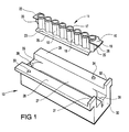
- the embodiment shown comprises a receptacle member generally indicated 11, having eight upwardly open receptacles or wells each generally indicated 12 in a row, and a receptacle member holder, generally indicated 13 for receiving the receptacle member 11 as will be described in more detail below.
- the receptacle member 11 is, in this embodiment, integrally formed of a suitable material such as suspension grade polystyrene or syndiotactic polypropylene, but other materials such as that sold under the trade mark Escorene made by Exxon or that sold under the trade reference XB80 12DNA by Nesté may be used.
- a suitable material such as suspension grade polystyrene or syndiotactic polypropylene, but other materials such as that sold under the trade mark Escorene made by Exxon or that sold under the trade reference XB80 12DNA by Nesté may be used.
- the particular properties of these materials are that they are adequately clear and transparent without being substantially adherent to cells to allow the preferred method of use described in more detail hereinbelow.
- Each receptacle 12 of the receptacle member 11 comprises an open ended generally cylindrical, slightly tapering tubular side wall 14 having an open end 15 and a closed end 16.
- the open end 15 is surrounded by a flange 17 and each pair of adjacent receptacles 12 is joined by a respective web 18.
- the bottom wall 16 is slightly rounded, upwardly concave, and joins the side wall 14 at a rounded corner 118.
- the diameter of each receptacle 12 is of the order of 3.5mm at the open end 15 reducing slightly due to the tapering side wall 14. This taper in the side wall is of practical significance only, in permitting the receptacle member to be released from the forming mould more readily.
- the centre-to-centre spacing or pitch between adjacent receptacles 12 is, in this embodiment, 9mm to allow use of the apparatus of the invention in cooperation with standard equipment in the so-called microtitre format.
- a single receptacle member 11, comprising 8 receptacles 12 can be filled from an 8-nozzle micropipette in a single operation. Such pipettes are known in the art and widely commercially available.
- an end tab 19 Projecting from one end of the receptacle member 11, parallel to the plane defined by the flanges 17, but spaced towards the bottoms 16 of the receptacles 12 from the open ends 15 is an end tab 19 below which is a locating rib 20 having a notch 21 between itself and the tab 19 for snap engagement with a support frame, or rack, 45 as shown in Figure 5.
- the tab 19 has a shaped recess 10, as can be seen in Figure 1, for cooperative engagement with one of a plurality of bosses or studs 51 on the rack 45 to determine the orientation of the receptacle member 11 when positioned on the rack.
- At the opposite end from the tab 19 there is a shorter tab 22 which has no recess 10 and below which is a further rib corresponding in shape to the rib 20.
- a transverse base flange 23 Projecting from the bottom of the receptacle member 11, laterally of the length thereof, is a transverse base flange 23 having a slightly inclined elongate limb 25 along each of its opposite free edges, the limbs 25 projecting below the bottoms 16 of the receptacles 12 to define two parallel supporting edges allowing the receptacle member 11 to be placed on a horizontal surface and remain stably upright despite the rounded bottoms 16 of the receptacles 12.
- each receptacle 12 together with its rounded bottom wall 16, allow a smaller cell sample to be used, the rounded bottom encouraging the incubation process by holding the cell sample in a more close-knit arrangement rather than allowing it to spread over a larger bottom wall as is the case with conventional "wells" having a 6 - 8 mm diameter and a flat bottom wall.
- the holder 13 for the receptacle member 11, as shown in Figure 1, comprises an elongate body having a central recess 27 and two opposite upper lateral flanges 28, 29 which define an upper face of the body 13.
- the flanges 28, 29 are provided with respective upstanding projections 31, 32 defining shoulders at the said one end 30, and two upstanding studs 33, 34 on respective flanges 28, 29 serve as locating studs as will be described below.
- the recess 27 is positioned, within the body 13, such as to be offset from a symmetrical position within the body 13, and is further from the end 30 than from the opposite end 35.
- each channel 36, 37 extending down from the upper face of the flanges 28, 29 by a distance less than the full depth of the recess 27, and each channel 36, 37 has a respective longitudinal slot 38, 39 for receiving the ribs 20 at each end of the receptacle member 11 when this is positioned in the recess 27.
- the longer tab 19 at the first end of the receptacle member 11 is intended to fit the longer channel 36 at the end 30 of the body 13, and the shorter tab 22 is intended to fit the shorter channel 37.
- the tab 19 projects from the end of the body 13 and this will prevent the body 13 being fitted to a standard retainer for a centrifuge as will be described in more detail below.
- the apparatus of the invention therefore is clearly provided with means for identifying the orientation of the receptacle member with respect to the holder.
- the open ends 15 of the receptacles 12 project slightly above the upper faces of the flanges 28, 29, but not so far as the projecting studs 33, 34.
- the holder body allows the receptacle member 11 to be fitted to a centrifuge by utilising a standard centrifuge clip such as a Shandon centrifuge retainer, with a microscope slide fitted to the retainer and a suitably shaped filter element positioned between the row of receptacle members and the microscope slide.
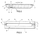
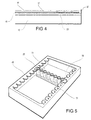
- An example filter member and microscope slide are identified with the reference numerals 40, 41 in Figure 4.
- the filter paper and microscope slide do not form part of the apparatus of the invention and are illustrated simply to show the manner in which the apparatus of the invention may be used.
- a standard centrifuge retainer can be used to press the microscope slide 41 against the filter paper 40, and this latter against the open ends 15 of the receptacles 12 by engaging under the flanges 28, 29 of the holder 13.
- the filter paper is thus pressed firmly against the flanges 17 and the microscope slide 41 supported over the whole of its surface area by the filter paper which is compressed between the upper surfaces of the flanges 28, 29 and the flanges 17.
- the difference in the surface height between the flanges 17 and the flanges 28, 29, is not so great, however, that the pressure exerted by the microscope slide causes significant compression of the paper to cause the filter paper to seal around the openings in the receptacles 12 to prevent absorbtion laterally into the absorbent material, but is sufficiently great to prevent leakage between the absorbent layer and either the microscope slide or the upper surfaces of the flanges 28, 29.
- the relative positions of the microscope slide 41 and the row of receptacles 12 is determined by the relative positions of the recess 27 and the shoulders defined by the upstanding ridges 31, 32.
- the distance between the end receptacle 12 and the end of the microscope slide nearest the end 30 of the holder body 13 is slightly greater than the distance between the receptacle at the other end of the row and the opposite end 35 of the holder body 13. This allows a clear visual discrimination between opposite ends of the microscope slide so that it can be positioned in the appropriate orientation. Since the receptacle member 11 can only be positioned within the recess 27 in one orientation the order of the specimens formed on the microscope slide is thus predetermined and cannot be reversed inadvertently.
- the microscope slide may be frosted or painted with a suitable markable material along one longitudinal edge over an area such as not to overlap with that to be used for the deposition of samples.
- a suitable markable material along one longitudinal edge over an area such as not to overlap with that to be used for the deposition of samples.
- Figure 5 illustrates a conventional microtitre format frame generally indicated 45 showing a receptacle member clipped in position between two opposite limbs. Up to 12 such members may be held on a single rack 45 to provide a 96 well sample array.
- the receptacle member is formed as a unitary body having ninety-six wells in twelve rows of eight columns, other embodiments may also be formed, for example allowing the formation of arrays having 192 wells, in twenty four rows of eight wells (the rows being spaced 4.5 mm instead of the standard 9 mm) or allowing the formation of arrays having 384 wells, in twenty four rows of sixteen wells (with both the rows, and the wells within the rows, being spaced by 4.5 mm).
- the apparatus described above may be used to carry out a comparative test on a plurality of samples, particularly cell samples.
- the test involves the introduction of respective cell samples into the individual receptacles, incubation of the cells samples in the receptacles under selected conditions and determination of the population of cells of a given type in the incubated samples in order to determine what type of further investigation should be carried out on the samples in situ in the receptacles.
- the further investigation may be carried out by a technique involving the transmission of light through the bottom wall of the receptacle, or by extracting the samples by centrifugation through the open ends thereof onto a receiver.
- a particularly useful application of the invention is in the assessment of tumour cells, and in this case the cell samples will include tumour cells and the said investigation may comprise an assessment of the percentage of tumour cells present in the cell population at the termination of the incubation stage.
- the investigation to determine the population of cells may be performed by first extracting the cells through the open end of the plurality of the receptacles by centrifuging onto a receiver such as a microscope slide, and counting the tumour cell population as a percentage of the total cell population.
Landscapes
- Health & Medical Sciences (AREA)
- Chemical & Material Sciences (AREA)
- Life Sciences & Earth Sciences (AREA)
- Immunology (AREA)
- Analytical Chemistry (AREA)
- General Health & Medical Sciences (AREA)
- Hematology (AREA)
- Chemical Kinetics & Catalysis (AREA)
- Engineering & Computer Science (AREA)
- Clinical Laboratory Science (AREA)
- Physics & Mathematics (AREA)
- Molecular Biology (AREA)
- Biochemistry (AREA)
- General Physics & Mathematics (AREA)
- Pathology (AREA)
- Biomedical Technology (AREA)
- Urology & Nephrology (AREA)
- Cell Biology (AREA)
- Biotechnology (AREA)
- Food Science & Technology (AREA)
- Medicinal Chemistry (AREA)
- Microbiology (AREA)
- Investigating Or Analysing Biological Materials (AREA)
- Automatic Analysis And Handling Materials Therefor (AREA)
- Optical Measuring Cells (AREA)
- Glass Compositions (AREA)
- Investigating Or Analyzing Materials By The Use Of Electric Means (AREA)
- Sampling And Sample Adjustment (AREA)
- Centrifugal Separators (AREA)
- Secondary Cells (AREA)
- Apparatus Associated With Microorganisms And Enzymes (AREA)
- Investigating Or Analysing Materials By The Use Of Chemical Reactions (AREA)
- Electric Double-Layer Capacitors Or The Like (AREA)
- Inorganic Insulating Materials (AREA)
- Investigating Or Analysing Materials By Optical Means (AREA)
Claims (20)
- Vorrichtung zur Bildung einer Mehrzahl von Zellproben in einem Aufnahmeteil (41) zur mikroskopischen Prüfung, bestehend aus einer Mehrzahl von Gefäßen (12) mit einem offenen Ende (15) und einem geschlossenen Ende (16), einer Halterung (13) für die Gefäße, die das Einsetzen in das Aufnahmeteil (41) erlaubt, wobei ein Absorbierungskörper (40) dazwischen angeordnet ist, wobei die Halterung eine Mehrzahl von Öffnungen und Haltemitteln für das Aufnahmeteil, den Absorbierungskörper, die Halterung und die Gefäße aufweist, um diese zusammengesetzt zu halten, wobei die offenen Enden der Gefäße mit dem Absorbierungskörper in Kontakt und in Reihe mit entsprechenden Öffnungen darin sind, so daß beim Zentrifugieren überstehende Flüssigkeit von dem Absorbierungskörper durch die Ränder der Öffnungen ohne Lecken des Verbindungsbereichs zwischen dem offenen Ende jedes Gefäßes und der entsprechenden Öffnung im Absorbierungskörper absorbiert werden kann,
dadurch gekennzeichnet,
daß die Gefäße (12) Verbindungen (18) miteinander aufweisen und ein einheitliches Gefäß (11) bilden, das aus wenigstens einer Reihe von Gefäßen besteht, daß die innere Oberfläche jedes Gefäßes im wesentlichen nicht-adhäsiv zu Zellmaterial ist, wobei wenigstens die Zellen einer Probe durch Zentrifugation aus dem Gefäß durch das offene Ende (15) auf das Aufnahmeteil (41) gebracht wird, und daß die Halterung (13) so aufgebaut ist, daß sie das einheitliche Gefäß (11) nur in einer bestimmten Ausrichtung aufnimmt und Anschläge (31, 32) besitzt, die die relative Position des einheitlichen Gefäßes (11) und des Aufnahmeteils (41) bei dem Zusammenbau definieren. - Vorrichtung nach Anspruch 1,
dadurch gekennzeichnet, daß die relativen Abmessungen des Gefäßteils (11) und der Halterung (13) derart beschaffen sind, daß die offenen Enden (15) der Gefäße (12) genügend weit über eine Stützfläche (28, 29) der Halterung ragen, um mit ihren Rändern den Absorbierungskörper (40) zu berühren, der während des Gebrauchs zwischen den oberen Enden der Gefäße und dem Aufnahmeteil (41) liegt, um eine Dichtung um die offenen Enden der Gefäße zu bilden. - Vorrichtung nach Anspruch 2,
dadurch gekennzeichnet,
daß die Stützfläche (28, 29) der Halterung (13) mit einem Anschlag (31, 32) versehen ist, mit dem das Aufnahmeteil (41) in Eingriff bringbar ist, um dessen Position in Bezug auf das Gefäßteil (11) festzulegen. - Vorrichtung nach Anspruch 2 oder 3,
dadurch gekennzeichnet,
daß die Halterung (13) einen Positioniervorsprung (33, 34) für die Verbindung mit einer Öffnung des Absorbierungskörpers, die abseits der besagten jeweiligen Öffnungen liegt, hat, der von ihrer Stützfläche (28, 29) hochragt. - Vorrichtung nach einem der vorhergehenden Ansprüche,
dadurch gekennzeichnet,
daß die Gefäße (12) des Gefäßteils (11) in einem im wesentlichen regelmäßigen Abstand zueinander angeordnet sind und die Mittel (36, 37, 38, 39, 19, 20, 22), die die relative Position des einheitlichen Gefäßteils (11) und des Aufnahmeteils (41) bestimmen, das Gefäßteil so positionieren, daß das Gefäß an einem ersten Ende der Reihe sich näher an dem angrenzenden Ende des Aufnahmeteils befindet, als das Gefäß an dem anderen Ende der Reihe in Bezug auf sein angrenzendes Ende des Aufnahmeteils. - Vorrichtung nach einem der vorhergehenden Ansprüche,
dadurch gekennzeichnet,
daß die geschlossenen Enden (16) der Gefäße (12) jeweils durch Bodenwände gebildet werden, daß alle Bodenwände der Gefäße eines Gefäßteils im wesentlichen auf einer Ebene liegen und daß wenigstens die Bodenwand jedes Gefäßes im wesentlichen transparent ist, um dadurch die Probe in dem Behälter durch eine optische Technik prüfen zu können, die Licht durch die Probe und die Bodenwand sendet, oder durch eine Technik, die den Transfer einer Probe durch Zentrifugation von dem Gefäß durch sein offenes Ende (15) auf das Aufnahmeteil einschließt. - Vorrichtung nach einem der vorhergehenden Ansprüche,
dadurch gekennzeichnet,
daß die Gefäße in einem Gefäßteil durch Stege (18) miteinander verbunden sind, die sie in dem bestimmten Abstand zueinander halten. - Vorrichtung nach einem der vorhergehenden Ansprüche,
dadurch gekennzeichnet,
daß das offene Ende (15) jedes Gefäßes einen umlaufenden Flansch (17) aufweist, der bei der Zentrifugation eine Kontaktfläche für den Absorbierungskörper (40) bildet. - Vorrichtung nach einem der vorhergehenden Ansprüche,
dadurch gekennzeichnet,
daß der Abstand zwischen den Mittelpunkten nebeneinanderliegender Gefäße (12) in einem Gefäßteil (11) im wesentlichen 4,5 oder 9 mm ist. - Vorrichtung nach einem der vorhergehenden Ansprüche,
dadurch gekennzeichnet,
daß die Bodenwand (16) jedes Gefäßes einen gekrümmten Querschnitt aufweist und daß die Verbindung (118) zwischen der Bodenwand und der Seitenwand abgerundet ist, um der Durchleitung von Licht durch die Bodenwand, auf die es einfällt, im wesentlichen nichts entgegenzusetzen. - Vorrichtung nach einem der vorhergehenden Ansprüche,
dadurch gekennzeichnet,
daß das Gefäßteil mit einem unteren Querflansch (23, 25) ausgebildet ist, die als Basis dient und das Gefäßteil aufrecht, mit den offenen Enden der Gefäße zuoberst, hält. - Vorrichtung nach einem der vorhergehenden Ansprüche,
dadurch gekennzeichnet,
daß das Gefäßteil eine Mehrzahl von Reihen und Kolonnen aufweist und daß mindestens eine Reihe oder Kolonnen von dem Gebilde als einzelne Einheit abtrennbar ist. - Vorrichtung nach Anspruch 8 oder einem der von Anspruch 8 abhängenden Ansprüche 9 bis 12,
dadurch gekennzeichnet,
daß die Flansche (17) die die offenen Enden umgeben aus einem opaken Material gebildet oder mit einem solchen beschichtet sind. - Set zur Bildung einer Mehrzahl von Zellproben auf einem Aufnahmeteil zur mikroskopischen Untersuchung, bestehend aus: einer Mehrzahl von Gefäßen (12), um zu untersuchende Proben aufzunehmen, wobei jedes Gefäß ein offenes Ende (15) und ein geschlossenes Ende (16) besitzt; eine Halterung (13) für die Gefäße; einen Absorbierungskörper (40) der eine Mehrzahl von Öffnungen aufweist; ein Aufnahmeteil (41), das die Proben von den Gefäßen empfängt; und Haltemittel, um die Halterung mit den Gefäßen darin, den Absorbierungskörper und das Aufnahmeteil zusammengesetzt zu halten, wobei die offenen Enden der Gefäße in Kontakt mit dem Absorbierungskörper stehen und in Reihe mit dessen jeweiligen Öffnungen liegen, so daß bei Zentrifugation überstehende Flüssigkeit durch die Ränder der Öffnungen des Absorbierungskörpers absorbiert werden kann, ohne daß der Verbindungsbereich zwischen dem offenen Ende jedes Gefäßes und der entsprechenden Öffnung des Absorbierungskörpers leckt,
dadurch gekennzeichnet,
daß die Gefäße (12) durch Verbindungen (18) zu einem einzigen Gefäßteil (11) verbunden sind, der wenigstens eine Reihe von Gefäßen aufweist, daß die innere Oberfläche jedes Gefäßes im wesentlichen nicht-adhäsiv für Zellmaterial ist, wodurch bei Zentrifugation wenigstens die Zellen einer Probe aus dem Gefäß durch sein offenes Ende (15) auf das Aufnahmeteil (41) transferiert werden, und daß die Halterung (13) das einheitliche Gefäßteil (11) nur in einer bestimmten Orientierung aufnehmen kann und Anschläge (31, 32) für den Anschlag des Aufnahmeteils aufweist, um die relative Position des einheitlichen Gefäßteils und des Aufnahmeteils beim Zusammenbau zu bestimmen und dabei die Orte festzulegen, an denen beim Gebrauch auf dem Aufnahmeteil Zellproben gebildet werden. - Set gemäß Anspruch 14,
dadurch gekennzeichnet,
daß das Gefäßteil (13) so in der Halterung (13) aufgenommen wird, daß die offenen Enden der Gefäße neben einer Stützfläche (28, 29) der Halterung liegen und die Stützfläche mindestens einen Positioniervorsprung (33, 34) der von ihr nach oben ragt aufweist und der Absorbierungskörper eine mit dem Positionierungsvorsprung zusammenwirkende Öffnung aufweist, die abseits der oben genannten Öffnungen liegt, wobei der Positioniervorsprung so angeordnet ist, daß der Absorbierungskörper mit seinen Öffnungen übereinstimmend mit den offenen Enden (15) der Gefäße positioniert wird, wenn das Set zusammengebaut wird. - Set gemäß Anspruch 15, bei dem das Aufnahmeteil (41) ein Objektträger ist und die die Stützfläche (28, 29) Halterung einen nach oben ragenden Anschlag (31, 32) aufweist, an dem der Objektträger (41) anliegt um ihn in einer bestimmten Position für den Empfang der Zellproben festzulegen.
- Set gemäß Anspruch 14, 15 oder 16,
dadurch gekennzeichnet,
daß die geschlossenen Enden (16) der Gefäße (12) aus Bodenwänden bestehen, daß alle Bodenwände der Gefäße im wesentlichen in einer ersten Ebene liegen und daß wenigstens die Bodenwand jedes Gefäßes wenigstens im wesentlichen transparent ist, um dadurch zu erlauben, die Probe in dem Gefäß mit einer optischen Technik zu untersuchen, bei der Licht durch die Probe und die Bodenwand geleitet wird oder durch eine Technik, die den Transfer der Probe durch Zentrifugation aus dem Gefäß durch sein offenes Ende (15) auf das Aufnahmeteil beinhaltet. - Set gemäß Anspruch 15, 16 oder 17,
dadurch gekennzeichnet,
daß einige der Gefäße einen Wirkstoff für das Testen der Zellproben beinhalten. - Set nach Anspruch 18, bei dem einige Gefäße eine toxische Substanz als positives Kontrollmittel für das Testen enthalten.
- Set nach Anspruch 18 oder 19, bei dem einige der Gefäße keine Substanz enthalten, um als negatives Kontrollmittel für das Testen zu dienen.
Priority Applications (1)
| Application Number | Priority Date | Filing Date | Title |
|---|---|---|---|
| EP96107947A EP0732575B1 (de) | 1992-10-14 | 1993-10-14 | Verfahren zur Ausführung von insbesondere vergleichenden Tests |
Applications Claiming Priority (3)
| Application Number | Priority Date | Filing Date | Title |
|---|---|---|---|
| EP92309364 | 1992-10-14 | ||
| EP92309364 | 1992-10-14 | ||
| PCT/GB1993/002127 WO1994009352A2 (en) | 1992-10-14 | 1993-10-14 | Method and apparatus for conducting tests, particularly comparative tests |
Related Child Applications (2)
| Application Number | Title | Priority Date | Filing Date |
|---|---|---|---|
| EP96107947A Division EP0732575B1 (de) | 1992-10-14 | 1993-10-14 | Verfahren zur Ausführung von insbesondere vergleichenden Tests |
| EP96107947.2 Division-Into | 1996-05-18 |
Publications (2)
| Publication Number | Publication Date |
|---|---|
| EP0664882A1 EP0664882A1 (de) | 1995-08-02 |
| EP0664882B1 true EP0664882B1 (de) | 1997-06-11 |
Family
ID=8211519
Family Applications (2)
| Application Number | Title | Priority Date | Filing Date |
|---|---|---|---|
| EP93922996A Expired - Lifetime EP0664882B1 (de) | 1992-10-14 | 1993-10-14 | Vorrichtung und verfahren zur ausführung von insbesondere vergleichenden tests |
| EP96107947A Expired - Lifetime EP0732575B1 (de) | 1992-10-14 | 1993-10-14 | Verfahren zur Ausführung von insbesondere vergleichenden Tests |
Family Applications After (1)
| Application Number | Title | Priority Date | Filing Date |
|---|---|---|---|
| EP96107947A Expired - Lifetime EP0732575B1 (de) | 1992-10-14 | 1993-10-14 | Verfahren zur Ausführung von insbesondere vergleichenden Tests |
Country Status (7)
| Country | Link |
|---|---|
| US (1) | US5650125A (de) |
| EP (2) | EP0664882B1 (de) |
| JP (1) | JPH09501488A (de) |
| AT (2) | ATE162888T1 (de) |
| AU (1) | AU5283393A (de) |
| DE (2) | DE69311568T2 (de) |
| WO (1) | WO1994009352A2 (de) |
Families Citing this family (46)
| Publication number | Priority date | Publication date | Assignee | Title |
|---|---|---|---|---|
| US6045760A (en) * | 1995-12-05 | 2000-04-04 | Hitachi Koki Co., Ltd. | Micro-plate adapter |
| FR2762911B1 (fr) * | 1997-04-30 | 1999-10-01 | Cytotech Distribution Sa | Dispositif et methode d'analyse de preparations cytologiques |
| US6258326B1 (en) | 1997-09-20 | 2001-07-10 | Ljl Biosystems, Inc. | Sample holders with reference fiducials |
| US6297018B1 (en) | 1998-04-17 | 2001-10-02 | Ljl Biosystems, Inc. | Methods and apparatus for detecting nucleic acid polymorphisms |
| US6982431B2 (en) | 1998-08-31 | 2006-01-03 | Molecular Devices Corporation | Sample analysis systems |
| USD416330S (en) | 1997-10-21 | 1999-11-09 | Bel-Art Products, Inc. | Multiwell fluid container for microbiological testing |
| JP2001520394A (ja) * | 1997-10-22 | 2001-10-30 | セーフティ アソシエイツ インコーポレイテッド | 種々の基質中の被検体を決定するための方法および装置 |
| AU3649199A (en) | 1998-04-17 | 1999-11-08 | Ljl Biosystems, Inc. | Sample-holding devices and systems |
| WO1999061152A1 (en) * | 1998-05-26 | 1999-12-02 | Mj Research, Inc. | Automation-compatible slide format sample cartridge |
| USD421130S (en) * | 1998-06-15 | 2000-02-22 | Bayer Corporation | Sample tube rack |
| US6074617A (en) * | 1998-07-10 | 2000-06-13 | Bayer Corporation | Stat shuttle adapter and transport device |
| US6399394B1 (en) | 1999-06-30 | 2002-06-04 | Agilent Technologies, Inc. | Testing multiple fluid samples with multiple biopolymer arrays |
| WO2001021311A1 (en) * | 1999-09-20 | 2001-03-29 | Princeton Separations | Device for multiple sample processing |
| GB0008563D0 (en) * | 2000-04-07 | 2000-05-24 | Cambridge Discovery Chemistry | Investigating different physical and/or chemical forms of materials |
| US6386749B1 (en) * | 2000-06-26 | 2002-05-14 | Affymetrix, Inc. | Systems and methods for heating and mixing fluids |
| US20020132360A1 (en) | 2000-11-17 | 2002-09-19 | Flir Systems Boston, Inc. | Apparatus and methods for infrared calorimetric measurements |
| US6821787B2 (en) | 2000-11-17 | 2004-11-23 | Thermogenic Imaging, Inc. | Apparatus and methods for infrared calorimetric measurements |
| US20060129329A1 (en) * | 2001-04-09 | 2006-06-15 | Kobylecki Ryszard J | Investigating different physical and/or chemical forms of materials |
| EP1405056A1 (de) * | 2001-06-15 | 2004-04-07 | Zeptosens AG | Körper für durchflussküvetten und deren verwendung |
| AU2002319595B2 (en) * | 2001-07-20 | 2007-06-07 | Gen-Probe Incorporated | Sample carrier and drip shield for use therewith |
| JP4235170B2 (ja) * | 2002-05-17 | 2009-03-11 | ジェン−プロウブ インコーポレイテッド | 離脱可能なロック機構を有するサンプルキャリア |
| AU2003239485B2 (en) | 2002-05-17 | 2008-11-20 | Gen-Probe Incorporated | Sample carrier having sample tube blocking means and drip shield for use therewith |
| US7537936B2 (en) * | 2002-05-31 | 2009-05-26 | Agilent Technologies, Inc. | Method of testing multiple fluid samples with multiple biopolymer arrays |
| US7910067B2 (en) | 2005-04-19 | 2011-03-22 | Gen-Probe Incorporated | Sample tube holder |
| JP4977708B2 (ja) * | 2005-09-06 | 2012-07-18 | フィンザイムズ・オサケユキテュア | サンプルプレートアセンブリおよび生体サンプルを処理する方法 |
| JP4680037B2 (ja) * | 2005-11-14 | 2011-05-11 | 株式会社エンプラス | 流体取扱装置およびそれに用いる流体取扱ユニット |
| US20070212775A1 (en) * | 2006-01-13 | 2007-09-13 | Finnzymes Instruments Oy | Microtiter plate, method of manufacturing thereof and kit |
| DE102006001881A1 (de) * | 2006-01-13 | 2007-07-19 | Roche Diagnostics Gmbh | Verpackungskassette für Reagenzienträger |
| JP4842788B2 (ja) * | 2006-03-16 | 2011-12-21 | 株式会社エンプラス | 流体取扱装置およびそれに用いる流体取扱ユニット |
| US7901626B2 (en) * | 2007-05-23 | 2011-03-08 | Enplas Corporation | Fluid handling unit and fluid handling apparatus using same |
| ES2660180T3 (es) * | 2007-12-07 | 2018-03-21 | Miltenyi Biotec Gmbh | Sistemas y métodos para procesamiento de células |
| JP5086159B2 (ja) * | 2008-04-04 | 2012-11-28 | 株式会社エンプラス | 流体取扱ユニットおよびそれを用いた流体取扱装置 |
| FI120818B (fi) * | 2008-05-28 | 2010-03-31 | Thermo Fisher Scientific Oy | Reaktioastia ja menetelmä sen käsittelemiseksi |
| JP5310447B2 (ja) * | 2009-09-30 | 2013-10-09 | 東洋紡株式会社 | 遠心機 |
| EP2335825A1 (de) * | 2009-12-21 | 2011-06-22 | F. Hoffmann-La Roche AG | Einheit und Vorrichtung zur Herstellung von Zellen und/oder Partikeln in einer Flüssigkeit und Verfahren zur mikroskopischen Analyse |
| US9144801B2 (en) | 2010-08-31 | 2015-09-29 | Abbott Laboratories | Sample tube racks having retention bars |
| GB201101488D0 (en) | 2011-01-28 | 2011-03-16 | Ge Healthcare Ltd | Container storing freeze dried biological sample |
| DE102012108158B4 (de) | 2012-09-03 | 2016-03-17 | Johann Wolfgang Goethe-Universität | Kapillarzelle, Anordnung und Verfahren zur Aufnahme, zur Positionierung und zur Untersuchung einer mikroskopischen Probe |
| WO2014144870A2 (en) | 2013-03-15 | 2014-09-18 | Abbott Laboratories | Light-blocking system for a diagnostic analyzer |
| US9632103B2 (en) | 2013-03-15 | 2017-04-25 | Abbott Laboraties | Linear track diagnostic analyzer |
| EP2972219B1 (de) | 2013-03-15 | 2022-01-19 | Abbott Laboratories | Automatisierter reagensmanager eines diagnostischen analysatorsystems |
| US11306282B1 (en) * | 2017-03-30 | 2022-04-19 | John L. Sternick | Modular multiple media tray system |
| CN110286119B (zh) * | 2019-06-28 | 2024-04-19 | 武汉明德生物科技股份有限公司 | 一种tip头探测框、样本类型检测模块组件及化学发光免疫分析仪 |
| DE112020007358T5 (de) * | 2020-08-31 | 2023-05-04 | Hitachi High-Tech Corporation | Biochemische analysevorrichtung, reaktionseinheit und kassettenführung |
| US11958053B2 (en) * | 2021-09-21 | 2024-04-16 | The Government of the United States of America, as represented by the Secretary of Homeland Security | Media holder for sample preparation |
| GB202303592D0 (en) * | 2023-03-10 | 2023-04-26 | Micromass Ltd | A vial carrier assembly |
Family Cites Families (17)
| Publication number | Priority date | Publication date | Assignee | Title |
|---|---|---|---|---|
| US3649464A (en) * | 1969-12-05 | 1972-03-14 | Microbiological Ass Inc | Assay and culture tray |
| US4154795A (en) * | 1976-07-23 | 1979-05-15 | Dynatech Holdings Limited | Microtest plates |
| FI790692A7 (fi) * | 1979-03-01 | 1980-09-02 | Suovaniemi Finnpipette | Mikrokyvettenhet |
| WO1982000360A1 (en) * | 1980-07-24 | 1982-02-04 | Oy Labsystems | Method and equipment for the measurement of properties of aliquid |
| DE3214317A1 (de) * | 1982-04-19 | 1983-12-15 | Behringwerke Ag, 3550 Marburg | Mikrotiterplatte |
| DE3467623D1 (en) * | 1983-01-15 | 1987-12-23 | Hoechst Ag | Sample stand |
| DE3316336C2 (de) * | 1983-05-04 | 1985-03-07 | Fa. Andreas Hettich, 7200 Tuttlingen | Zentrifugationskammer mit lösbarer Trägerplatte |
| US4682891A (en) * | 1985-05-31 | 1987-07-28 | Health Research, Incorporated | Microcircle system |
| US4735778A (en) * | 1985-08-28 | 1988-04-05 | Kureha Kagaku Kohyo Kabushiki Kaisha | Microtiter plate |
| GB2184837B (en) * | 1985-11-14 | 1990-08-22 | Tiyoda Seisakusho Kk | Cell for placing solid matters on a slide glass under centrifugal force |
| US4956150A (en) * | 1985-11-27 | 1990-09-11 | Alerchek | Disposable microtiter stick |
| US5084246A (en) * | 1986-10-28 | 1992-01-28 | Costar Corporation | Multi-well test plate |
| GB2204950A (en) * | 1987-05-14 | 1988-11-23 | Histopath Limited | Cytology sample chamber |
| AU2947289A (en) * | 1988-01-04 | 1989-08-01 | Oncotech Incorporated | Methods and apparatus assessing tumor resistance |
| FI87278C (fi) * | 1989-08-28 | 1992-12-10 | Labsystems Oy | Kyvettmatris och staellning foer denna |
| DE9203583U1 (de) * | 1992-03-17 | 1992-05-07 | Alcan Deutschland GmbH, 3400 Göttingen | Näpfchenplatte |
| CA2077853A1 (en) * | 1992-09-09 | 1994-03-10 | Kari Vauramo | Cuvette matrix tray |
-
1993
- 1993-10-14 EP EP93922996A patent/EP0664882B1/de not_active Expired - Lifetime
- 1993-10-14 DE DE69311568T patent/DE69311568T2/de not_active Expired - Fee Related
- 1993-10-14 WO PCT/GB1993/002127 patent/WO1994009352A2/en not_active Ceased
- 1993-10-14 AT AT96107947T patent/ATE162888T1/de not_active IP Right Cessation
- 1993-10-14 AU AU52833/93A patent/AU5283393A/en not_active Abandoned
- 1993-10-14 US US08/411,827 patent/US5650125A/en not_active Expired - Lifetime
- 1993-10-14 EP EP96107947A patent/EP0732575B1/de not_active Expired - Lifetime
- 1993-10-14 DE DE69316778T patent/DE69316778T2/de not_active Expired - Fee Related
- 1993-10-14 AT AT93922996T patent/ATE154436T1/de not_active IP Right Cessation
- 1993-10-14 JP JP6509773A patent/JPH09501488A/ja active Pending
Also Published As
| Publication number | Publication date |
|---|---|
| WO1994009352A3 (en) | 1994-06-23 |
| US5650125A (en) | 1997-07-22 |
| DE69316778T2 (de) | 1998-09-24 |
| EP0664882A1 (de) | 1995-08-02 |
| ATE162888T1 (de) | 1998-02-15 |
| JPH09501488A (ja) | 1997-02-10 |
| AU5283393A (en) | 1994-05-09 |
| ATE154436T1 (de) | 1997-06-15 |
| DE69311568D1 (de) | 1997-07-17 |
| EP0732575B1 (de) | 1998-01-28 |
| EP0732575A2 (de) | 1996-09-18 |
| DE69311568T2 (de) | 1998-02-19 |
| WO1994009352A2 (en) | 1994-04-28 |
| EP0732575A3 (de) | 1996-12-04 |
| DE69316778D1 (de) | 1998-03-05 |
Similar Documents
| Publication | Publication Date | Title |
|---|---|---|
| EP0664882B1 (de) | Vorrichtung und verfahren zur ausführung von insbesondere vergleichenden tests | |
| US5338666A (en) | Method for distributing a liquid sample into a multiple aliquot device | |
| US4591556A (en) | Apparatus and associated methods for use in microbiological, serological, immunological, clinical-chemical and similar laboratory work | |
| US4324859A (en) | Apparatus and associated methods for use in microbiological, serological, immunological, clinical-chemical and similar laboratory work | |
| US4877659A (en) | Multiwell assay/culture strip | |
| US3986534A (en) | Device for measuring and dispensing fractionary volumes of liquid samples | |
| US5976892A (en) | Method and apparatus for counting cells and microorganisms, particularly in food and biological fluids | |
| US5180555A (en) | Microbiological analysis cup or the like | |
| EP3148700B1 (de) | Einspaltiges mikroplattensystem und träger zur analyse biologischer proben | |
| US4162896A (en) | Micro-analysis process and device | |
| AU630219B2 (en) | Apparatus for microbiological testing | |
| WO1983000047A1 (en) | Improved biomedical analysis tray | |
| US6627432B2 (en) | Liquid flow and control in a biological test array | |
| US20040184965A1 (en) | Testing cup | |
| JP2004520593A (ja) | 微生物検査アレイ内の検査の統一性を維持する方法 | |
| US4298035A (en) | Method for measuring and dispensing fractionary volumes of liquid samples | |
| EP0213728A1 (de) | Verfahren und Vorrichtungen für chemische oder biologische Tests | |
| EP0028463A1 (de) | Verfahren zur Messung und Überführung vorbestimmter Volumen flüssiger Proben, insbesondere für die mikrobiologische Prüfung, und Vorrichtung zur mikrobiologischen Prüfung |
Legal Events
| Date | Code | Title | Description |
|---|---|---|---|
| PUAI | Public reference made under article 153(3) epc to a published international application that has entered the european phase |
Free format text: ORIGINAL CODE: 0009012 |
|
| 17P | Request for examination filed |
Effective date: 19950511 |
|
| AK | Designated contracting states |
Kind code of ref document: A1 Designated state(s): AT DE ES FR GB IT NL SE |
|
| 17Q | First examination report despatched |
Effective date: 19951109 |
|
| GRAG | Despatch of communication of intention to grant |
Free format text: ORIGINAL CODE: EPIDOS AGRA |
|
| GRAH | Despatch of communication of intention to grant a patent |
Free format text: ORIGINAL CODE: EPIDOS IGRA |
|
| GRAH | Despatch of communication of intention to grant a patent |
Free format text: ORIGINAL CODE: EPIDOS IGRA |
|
| GRAA | (expected) grant |
Free format text: ORIGINAL CODE: 0009210 |
|
| AK | Designated contracting states |
Kind code of ref document: B1 Designated state(s): AT DE ES FR GB IT NL SE |
|
| PG25 | Lapsed in a contracting state [announced via postgrant information from national office to epo] |
Ref country code: NL Free format text: LAPSE BECAUSE OF FAILURE TO SUBMIT A TRANSLATION OF THE DESCRIPTION OR TO PAY THE FEE WITHIN THE PRESCRIBED TIME-LIMIT Effective date: 19970611 Ref country code: IT Free format text: LAPSE BECAUSE OF FAILURE TO SUBMIT A TRANSLATION OF THE DESCRIPTION OR TO PAY THE FEE WITHIN THE PRESCRIBED TIME-LIMIT;WARNING: LAPSES OF ITALIAN PATENTS WITH EFFECTIVE DATE BEFORE 2007 MAY HAVE OCCURRED AT ANY TIME BEFORE 2007. THE CORRECT EFFECTIVE DATE MAY BE DIFFERENT FROM THE ONE RECORDED. Effective date: 19970611 Ref country code: ES Free format text: THE PATENT HAS BEEN ANNULLED BY A DECISION OF A NATIONAL AUTHORITY Effective date: 19970611 Ref country code: AT Effective date: 19970611 |
|
| REF | Corresponds to: |
Ref document number: 154436 Country of ref document: AT Date of ref document: 19970615 Kind code of ref document: T |
|
| XX | Miscellaneous (additional remarks) |
Free format text: TEILANMELDUNG 96107947.2 EINGEREICHT AM 18/05/96. |
|
| REF | Corresponds to: |
Ref document number: 69311568 Country of ref document: DE Date of ref document: 19970717 |
|
| PG25 | Lapsed in a contracting state [announced via postgrant information from national office to epo] |
Ref country code: SE Effective date: 19970911 |
|
| ET | Fr: translation filed | ||
| NLV1 | Nl: lapsed or annulled due to failure to fulfill the requirements of art. 29p and 29m of the patents act | ||
| PLBE | No opposition filed within time limit |
Free format text: ORIGINAL CODE: 0009261 |
|
| STAA | Information on the status of an ep patent application or granted ep patent |
Free format text: STATUS: NO OPPOSITION FILED WITHIN TIME LIMIT |
|
| 26N | No opposition filed | ||
| REG | Reference to a national code |
Ref country code: GB Ref legal event code: IF02 |
|
| PGFP | Annual fee paid to national office [announced via postgrant information from national office to epo] |
Ref country code: FR Payment date: 20041027 Year of fee payment: 12 |
|
| PGFP | Annual fee paid to national office [announced via postgrant information from national office to epo] |
Ref country code: DE Payment date: 20041228 Year of fee payment: 12 |
|
| PG25 | Lapsed in a contracting state [announced via postgrant information from national office to epo] |
Ref country code: DE Free format text: LAPSE BECAUSE OF NON-PAYMENT OF DUE FEES Effective date: 20060503 |
|
| PG25 | Lapsed in a contracting state [announced via postgrant information from national office to epo] |
Ref country code: FR Free format text: LAPSE BECAUSE OF NON-PAYMENT OF DUE FEES Effective date: 20060630 |
|
| REG | Reference to a national code |
Ref country code: FR Ref legal event code: ST Effective date: 20060630 |
|
| PGFP | Annual fee paid to national office [announced via postgrant information from national office to epo] |
Ref country code: GB Payment date: 20081021 Year of fee payment: 16 |
|
| PG25 | Lapsed in a contracting state [announced via postgrant information from national office to epo] |
Ref country code: GB Free format text: LAPSE BECAUSE OF NON-PAYMENT OF DUE FEES Effective date: 20091014 |